
John Deere 35D and 50D Excavator Repair Technical Manual TM2264 – PDF DOWNLOAD
$27.95
John Deere 35D and 50D Excavator Repair Technical Manual TM2264 – PDF DOWNLOAD
Description
John Deere 35D and 50D Excavator Repair Technical Manual TM2264 – PDF DOWNLOAD
FILE DETAILS:
John Deere 35D and 50D Excavator Repair Technical Manual TM2264 – PDF DOWNLOAD
Language : English
Pages :468
Downloadable : Yes
File Type : PDF
IMAGES PREVIEW OF THE MANUAL:

DESCRIPTION:
John Deere 35D and 50D Excavator Repair Technical Manual TM2264 – PDF DOWNLOAD
Foreword
- This manual is written for an experienced technician. Essential tools required in performing certain service work are identified in this manual and are recommended for use. Live with safety: Read the safety messages in the introduction of this manual and the cautions presented throughout the text of the manual.
- This is the safety-alert symbol. When you see this symbol on the machine or in this manual, be alert to the potential for personal injury. Technical manuals are divided in two parts: repair and operation and tests. Repair sections tell how to repair the components.
- Operation and tests sections help you identify the majority of routine failures quickly. Information is organized in groups for the various components requiring service instruction. At the beginning of each group are summary listings of all applicable essential tools, service equipment and tools, other materials needed to do the job, service parts kits, specifications, wear tolerances, and torque values.
- Technical Manuals are concise guides for specific machines. They are on-the-job guides containing only the vital information needed for diagnosis, analysis, testing, and repair. Fundamental service information is available from other sources covering basic theory of operation, fundamentals of troubleshooting, general maintenance, and basic type of failures and their causes.
TABLE OF CONTENTS:
John Deere 35D and 50D Excavator Repair Technical Manual TM2264 – PDF DOWNLOAD
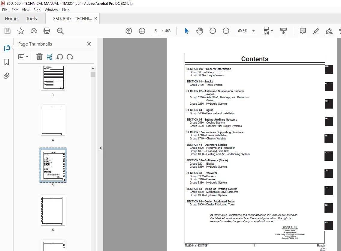
Contents 5
General Information 9
Safety 11
Recognize Safety Information 11
Follow Safety Instructions 11
Operate Only If Qualified 11
Wear Protective Equipment 12
Avoid Unauthorized Machine Modifications 12
Add Cab Guarding for Special Uses 12
Inspect Machine 13
Stay Clear of Moving Parts 13
Avoid High-Pressure Fluids 13
Beware of Exhaust Fumes 14
Prevent Fires 14
Prevent Battery Explosions 14
Handle Chemical Products Safely 15
Dispose of Waste Properly 15
Prepare for Emergencies 15
Use Steps and Handholds Correctly 16
Start Only From Operator’s Seat 16
Use and Maintain Seat Belt 16
Prevent Unintended Machine Movement 17
Avoid Work Site Hazards 17
Keep Riders Off Machine 18
Avoid Backover Accidents 18
Avoid Machine Tip Over 19
Use Special Care When Lifting Objects 19
Add and Operate Attachments Safely 20
Park and Prepare for Service Safely 20
Service Cooling System Safely 21
Remove Paint Before Welding or Heating 21
Make Welding Repairs Safely 22
Drive Metal Pins Safely 22
Torque Values 23
Torque Value 23
Metric Bolt and Cap Screw 23
Additional Metric Cap Screw Torque Values 24
Torque Value 26
Unified Inch Bolt and Cap Screw 26
Check Oil Lines and Fittings 27
Service Recommendations for O-Ring Boss Fittings 28
Service Recommendations For Flat Face O-Ring Seal Fittings 30
Service Recommendations for 37° Flare and 30° Cone Seat Connectors 31
Service Recommendations For Flared Connections—Straight or Tapered Threads 32
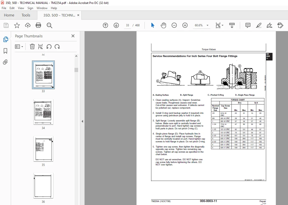
Service Recommendations For Inch Series Four Bolt Flange Fittings 33
Service Recommendations for Metric Series Four Bolt Flange Fitting 34
Tracks 35
Track System 37
Track Roller Remove and Install 37
Track Roller Oil Leakage Test 39
Track Roller Disassemble and Assemble 40
Inspect Metal Face Seals 41
Measure Track Carrier Roller Wear 43
Track Carrier Roller Remove and Install 43
Measure Rubber Track Lugs 45
Rubber Track Remove and Install 45
Steel Track Components Inspection 47
Track Shoe Remove and Install 50
Steel Track Remove and Install 52
Sprocket Remove and Install 54
Front Idler Remove and Install 55
Front Idler Disassemble and Assemble 56
Measure Front Idler Wear 57
Track Adjuster and Recoil Spring Remove and Install 58
Track Adjuster and Recoil Spring Disassemble and Assemble 59
Track Adjuster Cylinder Disassemble and Assemble 63
Axles and Suspension Systems (Travel) 67
Axle Shaft, Bearings, and Reduction Gears 69
Travel Gearbox Remove and Install 69
Travel Gearbox Disassemble and Assemble 72
Hydraulic System 81
Travel Motor Disassemble and Assemble 81
Rotary Manifold Disassemble and Assemble 90
Engine 93
Removal and Installation 95
Engine Remove and Install 95
Exhaust Manifold Remove and Install100
Muffler Remove and Install101
Thermostat Remove and Install102
Water Pump Remove and Install103
Intake Manifold Remove and Install105
Fuel Injection Pump Remove and Install106
Fuel Injection Nozzles Remove and Install115
Fuel Injection Nozzles Disassemble and Assemble118
Rocker Arm Cover Remove and Install121
Rocker Arm Shaft Assembly Repair122
Cylinder Head Remove and Install125
Cylinder Head and Valves Disassemble and Assemble131
Piston and Connecting Rod Remove and Install139
Preliminary Piston and Rod Checks146
Piston and Connecting Rod Disassemble and Assemble147
Cylinder Block Repair158
Check Engine Rotation for Excessive Tightness163
Crankshaft and Main Bearing Failure Analysis164
Replace Crankshaft Front Oil Seal164
Measure Crankshaft End Play165
Flywheel Remove and Install166
Crankshaft Rear Oil Seal Replace166
Crankcase Extension Housing Remove and Install167
Flywheel Housing Remove and Install168
Crankshaft and Main Bearings Repair168
Measure Valve Lift177
Timing Gear Cover Remove and Install178
Camshaft End Play Check179
Timing Gear Backlash Check180
Camshaft Remove and Install181
Idler Gear Remove and Install188
Timing Gear Cover Mounting Plate Remove and Install190
Oil Pan and Strainer Remove and Install191
Oil Pump Remove and Install192
Oil Pump Disassemble, Inspect, and Assemble193
Oil Pressure Regulating Valve Remove and Install195
Oil Filter Adapter Remove and Install196
Engine Auxiliary Systems197
Cooling System199
Radiator Remove and Install199
External Fuel Supply Systems203
Fuel Tank Remove and Install203
Bleed Fuel System205
Frame or Supporting Structure207
Frame Installation209
Welding on Machine209
Welding Repair of Major Structure210
Chassis Weights213
Counterweight Remove and Install213
Operators Station215
Removal and Installation217
Cab Remove and Install217
Canopy Remove and Install218
Platform Remove and Install220
Seat and Seat Belt225
Seat Remove and Install225
Seat Base Remove and Install226
Seat Belt Remove and Install228
Heating and Air Conditioning System229
Refrigerant Cautions and Proper Handling229
Flush and Purge Air Conditioner System231
R134a Refrigerant Oil Information234
R134a Refrigerant Recovery / Recycling and Charging Station Installation Procedure235
Recover R134a Refrigerant236
Evacuate R134a System237
Charge R134a System238
Air Conditioner Compressor Remove and Install239
Receiver-Dryer Remove and Install240
Condenser Remove and Install240
Air Conditioner / Heater Module Remove and Install242
Heater Control Valve Remove and Install245
Bulldozers (Blade)247
Blades249
Blade Remove and Install249
Blade Disassemble and Assemble252
Hydraulic System253
Blade Cylinder Remove and Install253
Blade Pilot Controller Remove and Install255
Blade Pilot Controller Disassemble and Assemble258
Excavator261
Buckets264
Tooth Shank Remove and Install264
Frames267
Bucket Link Remove and Install267
Arm Remove and Install270
Boom Remove and Install274
Boom Swing Remove and Install279
Inspect Arm, Boom, Bucket, and Boom Swing Pins and Bushings282
Bushing and Seal Remove and Install285
Hydraulic System287
Hydraulic Pump Remove and Install287
Hydraulic Pump Disassemble290
Hydraulic Pump Assemble298
Hydraulic Pump Start-Up Procedure304
Dampener Drive (Flex Coupling) Remove and Install304
Solenoid Valve Manifold Disassemble and Assemble306
Pilot Controller Remove and Install307
Pilot Controller Disassemble and Assemble309
Travel Pilot Controller Remove and Install311
Travel Pilot Controller Disassemble and Assemble314
Boom Swing or Auxiliary Pilot Controller Remove and Install316
Boom Swing or Auxiliary Pilot Controller Disassemble and Assemble318
Control Valve Remove and Install320
Control Valve Disassemble and Assemble322
Pilot Controller Pattern Conversion Valve Remove and Install330
Pilot Controller Pattern Conversion Valve Disassemble and Assemble332
Hydraulic Tank Remove and Install334
Hydraulic Oil Cooler Remove and Install335
Boom Cylinder Remove and Install338
Arm Cylinder Remove and Install341
Bucket Cylinder Remove and Install344
Boom Swing Cylinder Remove and Install348
Boom Cylinder Disassemble and Assemble351
Arm Cylinder Disassemble and Assemble355
Bucket Cylinder Disassemble and Assemble359
Blade and Boom Swing Cylinder Disassemble and Assemble362
Hydraulic Cylinder Bleed Procedure366
Swing or Pivoting System367
Mechanical Drive Elements369
Swing Gearbox Remove and Install369
Swing Gearbox Disassemble and Assemble372
Upperstructure Remove and Install376
Swing Bearing Remove and Install378
Hydraulic System381
Swing Motor and Park Brake Remove and Install381
Swing Motor and Park Brake Disassemble and Assemble384
Swing Motor Start-Up Procedure388
Dealer Fabricated Tools389
Dealer Fabricated Tools391
ST4920 Track Recoil Spring Disassembly and Assembly Tool391
DFT1087 Track Recoil Spring Disassembly and Assembly Guard Tool395
Page Numbers 5
Section 000 9
Group 0001 11
S.M 4/1/25