John Deere 330LC and 370 Excavator Repair Technical Manual TM1670 – PDF DOWNLOAD
$28.95
John Deere 330LC and 370 Excavator Repair Technical Manual TM1670 – PDF DOWNLOAD
Description
John Deere 330LC and 370 Excavator Repair Technical Manual TM1670 – PDF DOWNLOAD
FILE DETAILS:
John Deere 330LC and 370 Excavator Repair Technical Manual TM1670 – PDF DOWNLOAD
Language : English
Pages :736
Downloadable : Yes
File Type : PDF
IMAGES PREVIEW OF THE MANUAL:
DESCRIPTION:
John Deere 330LC and 370 Excavator Repair Technical Manual TM1670 – PDF DOWNLOAD
Foreword
- This manual is written for an experienced technician. Essential tools required in performing certain service work are identified in this manual and are recommended for use. Live with safety: Read the safety messages in the introduction of this manual and the cautions presented throughout the text of the manual.
- This is the safety-alert symbol. When you see this symbol on the machine or in this manual, be alert to the potential for personal injury. Technical manuals are divided in two parts: repair and operation and tests. Repair sections tell how to repair the components.
- Operation and tests sections help you identify the majority of routine failures quickly. Information is organized in groups for the various components requiring service instruction. At the beginning of each group are summary listings of all applicable essential tools, service equipment and tools, other materials needed to do the job, service parts kits, specifications, wear tolerances, and torque values.
- Technical Manuals are concise guides for specific machines. They are on-the-job guides containing only the vital information needed for diagnosis, analysis, testing, and repair. Fundamental service information is available from other sources covering basic theory of operation, fundamentals of troubleshooting, general maintenance, and basic type of failures and their causes.
TABLE OF CONTENTS:
John Deere 330LC and 370 Excavator Repair Technical Manual TM1670 – PDF DOWNLOAD
Contents 5
General Information 9
Safety 11
Follow Safe Procedures 11
Prepare for Emergencies 11
Handle Fluids Safely—Avoid Fires 11
Prevent Battery Explosions 12
Handle Chemical Products Safely 12
Prevent Acid Burns 13
Avoid High-Pressure Fluids 14
Warn Others of Service Work 14
Park Machine Safely 15
Support Machine Properly 15
Operate Only from Operator’s Seat 15
Stay Clear of Moving Parts 16
Avoid Power Lines 16
Use Handholds and Steps 16
Keep Riders Off Machine 17
Move and Operate Machine Safely 17
Wear Protective Clothing 17
Protect Against Flying Debris 18
Protect Against Noise 18
Illuminate Work Area Safely 18
Service Machines Safely 18
Remove Paint Before Welding or Heating 19
Avoid Heating Near Pressurized Fluid Lines 19
Beware of Exhaust Fumes 20
Use Proper Lifting Equipment 20
Service Cooling System Safely 20
Dispose of Waste Properly 21
Work in a Clean Area 21
Use Tools Properly 22
Replace Safety Signs 22
Live With Safety 22
General Specifications 23
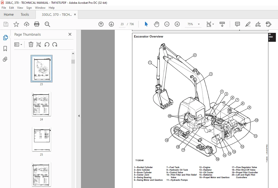
Excavator Overview 23
330LC Specifications 24
370 Specifications 26
330LC Working Ranges 28
370 Working Ranges 32
330LC and 370 Engine Specifications 34
330LC and 370 Drain and Refill Capacities 35
Torque Values 37
Unified Inch Bolt and Screw Torque Values 37
Metric Bolt and Screw Torque Values 38
Additional Metric Cap Screw Torque Values 39
Check Oil Lines And Fittings 41
Service Recommendations for O-Ring Boss Fittings 42
Service Recommendations For Flat Face O-Ring Seal Fittings 44
Service Recommendations for 37° Flare and 30° Cone Seat Connectors 46
Service Recommendations For Flared Connections—Straight or Tapered Threads 47
Service Recommendations For Inch Series Four Bolt Flange Fittings 48
Service Recommendations for Metric Series Four Bolt Flange Fitting 49
Fuels and Lubricants 51
Diesel Fuel 51
Lubricity Of Diesel Fuels 51
Low Sulfur Diesel Fuel Conditioner 52
Diesel Fuel Storage 52
Fuel Tank 53
Do Not Use Galvanized Containers 53
Diesel Engine Oil 54
Hydraulic Oil 55
Gear Oil 56
Track Roller, Front Idler, and Carrier Roller Oil 56
Track Adjuster, Working Tool Pivot, Swing Bearing, and Swing Bearing Gear Grease 57
Oil Filters 57
Lubricant Storage 58
Alternative and Synthetic Lubricants 58
Mixing of Lubricants 58
Tracks 59
Track System 61
Service Equipment and Tools 61
Other Material 65
Specifications 66
Track Roller 71
Measure Wear 71
Remove and Install 72
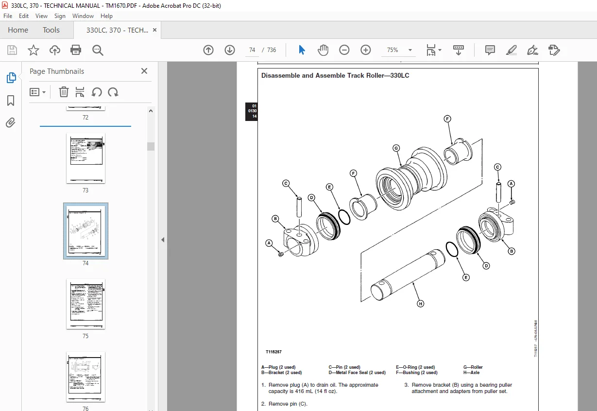
Disassemble and Assemble—330LC 74
Disassemble and Assemble—370 76
Oil Leakage Test 78
Track Carrier Roller 79
Measure Wear 79
Remove and Install 80
Disassemble and Assemble—330LC 82
Disassemble and Assemble—370 84
Metal Face Seals 86
Inspect 86
Track Shoe 87
Measure Grouser Wear 87
Remove and Install 88
Track Chain 89
Measure Link Wear 89
Measure Bushing Wear 89
Measure Pitch 90
Remove—330LC 90
Install—330LC 93
Remove—370 94
Install—370 96
Disassemble and Assemble—330LC 98
Disassemble and Assemble—370100
Replace Broken Part101
Track Sag103
Adjust103
Spocket105
Remove and Install105
Front Idler106
Measure Wear106
Remove and Install107
Disassemble—330LC108
Assemble—330LC109
Disassemble—370111
Assemble—370113
Oil Leakage Test117
Track Adjuster Cylinder and Recoil Spring117
Remove and Install 117
Track Adjuster and Recoil Spring119
Disassemble and Assemble119
Track Adjuster Cylinder124
Disassemble and Assemble—330LC124
Disassemble and Assemble—370126
Axles and Suspension Systems129
Axle Shaft, Bearings, and Reduction Gears131
Service Equipment and Tools131
Other Material132
Specifications133
Towing Machine135
Propel Gearbox136
Remove and Install—330LC136
Remove and Install—370139
Disassemble—330LC142
Metal Face Seals150
Inspect150
Propel Gearbox152
Assemble—330LC152
Disassemble—370162
Metal Face Seals169
Inspect169
Propel Gearbox172
Assemble—370172
Hydraulic System179
Essential Tools179
Service Equipment and Tools179
Other Material181
Specifications182
Propel Motor and Park Brake185
Remove and Install—330LC185
Start-Up Procedure—330LC187
Remove and Install—370188
Start-Up Procedure—330LC190
Disassemble—330LC192
Assemble—330LC198
Propel Motor Brake Valve Housing206
Disassemble and Assemble—330LC206
Propel Motor and Brake210
Disassemble—370210
Propel Motor Crossover Relief Valve220
Remove and Install—370220
Speed Selector Valve220
Remove and Install—370220
Counterbalance Valve222
Remove and Install—370222
Disassemble and Assemble—370224
Rotary Manifold227
Remove and Install227
Disassemble and Assemble230
Air Test232
Engine233
Removal and Installation235
POWERTECH® 81 L (6081) John Deere Engine—Use CTM86235
Alternators and Starting Motors—Use CTM77235
Essential Tools235
Service Equipment and Tools236
Other Material237
Specifications238
Engine239
Remove239
Install244
Remove and Install Engine Oil Pan249
Engine250
Disassemble and Assemble250
Fuel Injection Pump251
Remove and Install251
Repair251
Water Pump251
Remove251
Install253
Thermostats255
Remove and Test255
Install256
Fuel Supply Pump257
Remove257
Install257
Fuel Injection Nozzles258
Remove258
Install260
Bleed the Fuel System264
Clean the Engine Crankcase Ventilation Tube264
Check and Adjust Engine Valve Lash (Clearance)265
Starter268
Remove and Install268
Engine Auxiliary Systems269
Cold Weather Starting Aids271
Specifications271
Engine Coolant Heater271
Remove and Install271
Cooling System273
Service Equipment and Tools273
Specifications273
Fan, Shroud, and Guards274
Remove and Install274
Radiator and Oil Cooler275
Remove and Install275
Radiator and Oil Cooler Assembly278
Disassemble and Assemble278
Coolant Expansion Tank279
Remove and Install279
Fan and Air Conditioner Belts280
Remove and Install280
Speed Controls281
Service Equipment and Tools281
Specifications282
Fast and Slow Idle Stops282
Engine Speed Control Cable285
Remove and Install285
Engine Control Motor286
Remove and Install286
Engine Control Motor and Sensor 287
Adjustment287
Engine Speed Learning288
Fuel Shut-Off Solenoid290
Remove and Install290
Fuel Shut-Off Solenoid Linkage291
Check and Adjustment291
Intake System293
Essential Tools293
Service Equipment and Tools293
Specifications293
Air Intake System Leakage294
Test294
Air Cleaner295
Remove and Install295
Charge Air Cooler295
Remove and Install295
External Exhaust Systems299
Remove and Install Muffler299
External Fuel Supply Systems301
Other Material301
Specifications301
Fuel Tank302
Remove and Install302
Primary Fuel Filter (Water Separator)303
Remove and Install303
Disassemble and Assemble305
Final Fuel Filter Element306
Replace306
Final Fuel Filter Check Valve307
Replace307
Bleed the Fuel System308
Dampener Drive (Flex Coupling)309
Elements311
Other Material311
Specifications311
Dampener Drive (Flex Coupling)312
Remove and Install312
Splitter Drive315
Removal and Installation317
Other Material317
Specifications317
Splitter Housing318
Remove and Install318
Disassemble321
Assemble324
Electrical System327
Batteries, Support, and Cables329
Service Equipment and Tools329
Specifications330
Handle Batteries Safely331
Battery332
Procedure for Testing332
Electrolyte Specific Gravity333
Checking333
Battery335
Check Electrolyte Level and Terminals335
Booster Batteries and 24-Volt System337
Using337
Battery338
Charge338
Engine Speed Learning340
Battery342
Remove and Install342
12-Volt Accessories343
Adding343
Alternator, Regulator, and Charging System Wiring345
Alternators and Starting Motors—Use CTM77345
Specifications345
Alternator346
Remove and Install346
Wiring Harness and Switches349
Essential Tools349
Specifications350
Functional Schematic and Component Location351
Legend351
Component Location Drawing355
Cab355
Frame and Engine357
Engine and Pump Controller (EPC) Harness Connector359
Connecting359
Spring Wire Retainer Connectors359
Disconnecting359
Tab Retainer Connectors360
Disconnecting360
Fuses360
Replacing360
Fuse (Blade-Type) Color Codes362
Cab Ground Straps362
Remove and Install362
Starter Switch362
Remove and Install362
Engine Speed Learning363
Dome Light Switch365
Remove and Install365
Travel Alarm Cancel Switch and Start Aid Switch365
Remove and Install365
Replace DEUTSCH™ Connectors366
Install DEUTSCH™ Contact367
Replace WEATHER PACK™ Connector369
Install WEATHER PACK™ Contact370
Remove Connector Body from Blade Terminals371
System Controls373
Specifications373
Engine Speed Learning373
Engine and Pump Controller (EPC) Harness Connector374
Connecting374
Engine and Pump Controller (EPC)375
Remove and Install375
Monitor Controller375
Remove and Install375
Instruments and Indicators377
Replace Monitor Panel and Switch Panel Bulb377
Monitor Panel377
Remove and Install377
Hour Meter378
Remove and Install378
Travel Alarm Volume379
Change379
Frame or Supporting Structure381
Frame Installation383
Specifications383
Welding On Machine383
Welding Repair of Major Structure385
Chassis Weights387
Service Equipment and Tools387
Specifications387
Counterweight388
Remove and Install388
Operator’s Station389
Removal and Installation391
Specifications391
Cab391
Remove and Install391
Operator Enclosure397
Other Material397
Windowpane397
Remove and Install Two Piece Molding397
Remove and Install One Piece Molding399
Sliding Windows400
Remove and Install400
Windowpane Dimensions402
Seat and Seat Belt405
Specifications405
Seat405
Check Adjustments405
Remove and Install406
Seat Belt412
Remove and Install412
Inspect413
Heating and Air Conditioning415
Essential Tools415
Service Equipment and Tools416
Other Material418
Specifications418
Proper R134a Refrigerant Handling419
R134a Refrigerant419
Cautions419
R134a Compressor Oil Charge420
Check420
R134a Compressor Oil420
Removal420
R134a Component Oil421
Charge421
R134a Refrigerant Recovery, Recycling and Charging422
Station Installation Procedure422
Recover R134a System423
Evacuate R134a System424
R134a Refrigerant Recovery, Recycling, Charging425
Charge R134a System425
Heater Core and Blower Motor426
Remove and Install426
Heater Hoses429
Remove and Install429
Air Conditioning Compressor432
Remove and Install432
Disassemble and inspect433
Assemble441
Air Conditioning Compressor Manifolds444
Inspect444
Receiver Dryer446
Remove and Install446
Evaporator448
Remove and Install448
Condenser450
Remove and Install450
Excavator453
Buckets455
Other Material455
Specifications455
Bucket Tooth456
Replace456
Bucket Tooth Tip, Heavy-Duty Bucket457
Replace457
Tooth Shank457
Remove and install457
Cutting Edge461
Replace Welded461
Cutting Edge, bucket462
Repair Cracked462
Bucket463
Remove and Install463
Adjust Pivot End Play464
Disassemble and Assemble466
Pin-Up Data468
Frames469
Service Equipment and Tools469
Other Material469
Specifications470
Bucket Links474
Remove and Install474
Arm475
Remove and Install475
Boom479
Remove and Install479
Arm and Boom Pins and Bushings484
Inspect484
Bushings and Seals486
Remove and Install486
Hydraulic System487
Essential Tools487
Service Equipment and Tools487
Other Material490
Specifications491
Control Lever Pattern Conversion500
Lower Boom with Engine Stopped502
Hydraulic Oil Cleanup Procedure Using Portable Filter Caddy503
Hydraulic Pump 504
Remove and Install504
Start-Up Procedure507
Hydraulic Pump and Splitter Drive507
Main Hydraulic Pump 508
Disassemble508
Assemble518
Hydraulic Pump Regulator526
Disassemble and Assemble526
Pilot Pump530
Remove and Install530
Disassemble and Assemble 532
Pilot Pressure Regulating Valve and Filter534
Remove and Install534
Disassemble and Assemble536
Pilot Shut-Off Valve536
Remove and Install536
Linkage Adjustment538
Disassemble and Assemble 539
Proportional Solenoid Valve Manifold541
Remove and Install541
Proportional Solenoid Valve544
Disassemble and Assemble544
Dig Function Pilot Controller547
Remove and Install547
Disassemble and Assemble551
Propel Pilot Controller554
Remove and Install554
Disassemble and Assemble556
Flow Regulator Valve559
Remove and Install559
Disassemble and Assemble562
Control Valve563
Remove and Install563
Disassemble and Assemble572
Hydraulic Oil Tank595
Remove and Install595
Disassemble and Assemble602
Return Filter and Bypass Valve603
Remove and Install603
Suction Strainer605
Remove and Install605
Hydraulic Oil Tank Relief Valve and Breather Filter Cap607
Disassemble and Assemble607
Restriction Valve608
Remove and Install608
Oil Cooler Bypass Valve609
Remove and Install609
Radiator and Oil Cooler611
Remove and Install611
Radiator and Oil Cooler Assembly614
Disassemble and Assemble614
Boom Cylinder615
Remove and Install615
Cylinder Arm619
Remove and Install619
Bucket Cylinder621
Remove and Install621
Hydraulic Cylinder Bleed Procedure626
Boom, Arm or Bucket Cylinder628
Disassemble628
Assemble641
Swing or Pivoting System647
Mechanical Drive Elements649
Service Equipment and Tools649
Other Material650
Specifications651
Swing Gearbox652
Remove and Install652
Start-Up Procedure655
Swing Gearbox655
Swing Gearbox656
Disassemble and Assemble656
Upperstructure664
Remove—330LC664
Install—330LC669
Remove—370672
Install—370677
Swing Bearing680
Remove and Install680
Disassemble and Assemble681
Swing Bearing Upper Seal684
Install684
Swing Bearing Lower Seal685
Install685
Hydraulic System687
Specifications687
Swing Motor and Park Brake687
Remove and Install687
Start-Up Procedure689
Disassemble690
Assemble696
Swing Motor Make-Up and Crossover Relief Valves702
Disassemble and Assemble 702
Swing Motor Park Brake Relief Valve704
Disassemble and Assemble704
Dealer Fabricated Tools705
Dealer Fabricated Tools707
ST4920 Track Recoil Spring Disassembly and Assembly Tool707
DFT1087 Track Recoil Spring Disassembly and Assembly Guard Tool711
DFT1112 Spacer—330LC712
DFT1129 Spacer—370713
DF1036A Propel Gearbox Nut Wrench—330LC714
DFT1109 Holding Bar—330LC715
DF1063 Lift Bracket715
DFT1130 Adapter717
DF1038 Torque Adapter718
DFT1075 Propel Gearbox Nut Wrench—370719
DF1037 Hydraulic Pump Torque Adapter720
Rotary Manifold Lifting Tool721
DFT1089 Barrel Support722
Guide Pin723
DFT1119 Pump Support724
Page Numbers 5
Section 00 9
Group 0001 11
S.M 6/1/25