Trusted Business
Verified & Licensed
Virus Free Files
100% Safe Downloads
Secure Payment
SSL Protected
Instant Delivery
Available Immediately
John Deere 244J and 304J Loaders Repair Technical Manual TM2207 PDF
$29.95
John Deere 244J and 304J Loaders Repair Technical Manual TM2207 – PDF DOWNLOAD
Instant PDF Download
Available immediately
Save to Your Device
Download & keep forever
Antivirus Scanned
100% virus-free
Trusted Worldwide
175,000+ customers
Description
John Deere 244J and 304J Loaders Repair Technical Manual TM2207 – PDF DOWNLOAD
FILE DETAILS:
John Deere 244J and 304J Loaders Repair Technical Manual TM2207 – PDF DOWNLOAD
Language : English
Pages : 406
Downloadable : Yes
File Type : PDF
IMAGES PREVIEW OF THE MANUAL:
TABLE OF CONTENTS:
John Deere 244J and 304J Loaders Repair Technical Manual TM2207 – PDF DOWNLOAD
Contents 5
General Information 9
Safety Information 11
Recognize Safety Information 11
Follow Safety Instructions 11
Operate Only If Qualified 12
Wear Protective Equipment 12
Avoid Unauthorized Machine Modifications 12
Add Cab Guarding For Special Uses 13
Inspect Machine 13
Stay Clear of Moving Parts 13
Avoid High-Pressure Oil 14
Beware of Exhaust Fumes 14
Prevent Fires 15
Prevent Battery Explosions 15
Handle Chemical Products Safely 16
Dispose of Waste Properly 16
Prepare for Emergencies 16
Use Steps and Handholds Correctly 17
Start Only From Operator’s Seat 17
Use and Maintain Seat Belt 17
Prevent Unintended Machine Movement 18
Avoid Work Site Hazards 18
Use Special Care When Operating Loader 19
Keep Riders Off Machine 19
Avoid Backover Accidents 20
Avoid Machine Tip Over 20
Operating on Slopes 21
Operating Or Traveling On Public Roads 21
Inspect and Maintain ROPS 22
Add and Operate Attachments Safely 22
Park And Prepare For Service Safely 23
Service Cooling System Safely 23
Remove Paint Before Welding or Heating 24
Make Welding Repairs Safely 24
Drive Metal Pins Safely 25
Torque Values 27
Torque Value 27
Metric Bolt and Cap Screw 27
Additional Metric Cap Screw Torque Values 28
Torque Value 30
Unified Inch Bolt and Cap Screw 30
Service Recommendation 31
Metric 24° O-Ring Seal DIN 20078 31
Service Recommendations For Non-Restricted Banjo (Adjustable) Fittings 33
Service Recommendations For O-Ring Boss Fittings With Shoulder 35
Service Recommendations for Metric Series Four Bolt Flange Fitting 38
Service Recommendations For Inch Series Four Bolt Flange Fittings 39
Service Recommendation 40
Inch Series Four Bolt Flange For High Pressure 40
Wheels 41
Wheels and Fasteners 43
Wheel Remove and Install 43
Tire Remove and Install 44
Axles and Suspension System 45
Removal and Installation 48
Front Axle Remove and Install 48
Rear Axle Remove and Install 52
Axle Shafts and U-Joints 55
Drive Shaft Remove and Install 55
Axle Shaft, Bearings, and Rear Axle Reduction Gears 57
Front Axle Planetary Drive Disassemble and Assemble 57
Rear Axle Planetary Drive Disassemble and Assemble 59
Front Axle Brake and Differential Lock Assemblies Disassemble—244J 61
Front Axle Brake and Differential Lock Assemblies Assemble—244J 65
Front Axle Brake Assemblies Disassemble and Assemble—304J 73
Front Axle Differential and Pinion Disassemble—244J 80
Front Axle Differential and Pinion Assemble—244J 84
Front Axle Differential, Pinion, and Differential Lock Disassemble—304J 95
Front Axle Differential, Pinion, and Differential Lock Assemble—304J 99
Rear Axle Knuckle Housing Remove and Install109
Front Axle Shaft Remove and Install110
Rear Axle Shaft and Bearing Remove and Install110
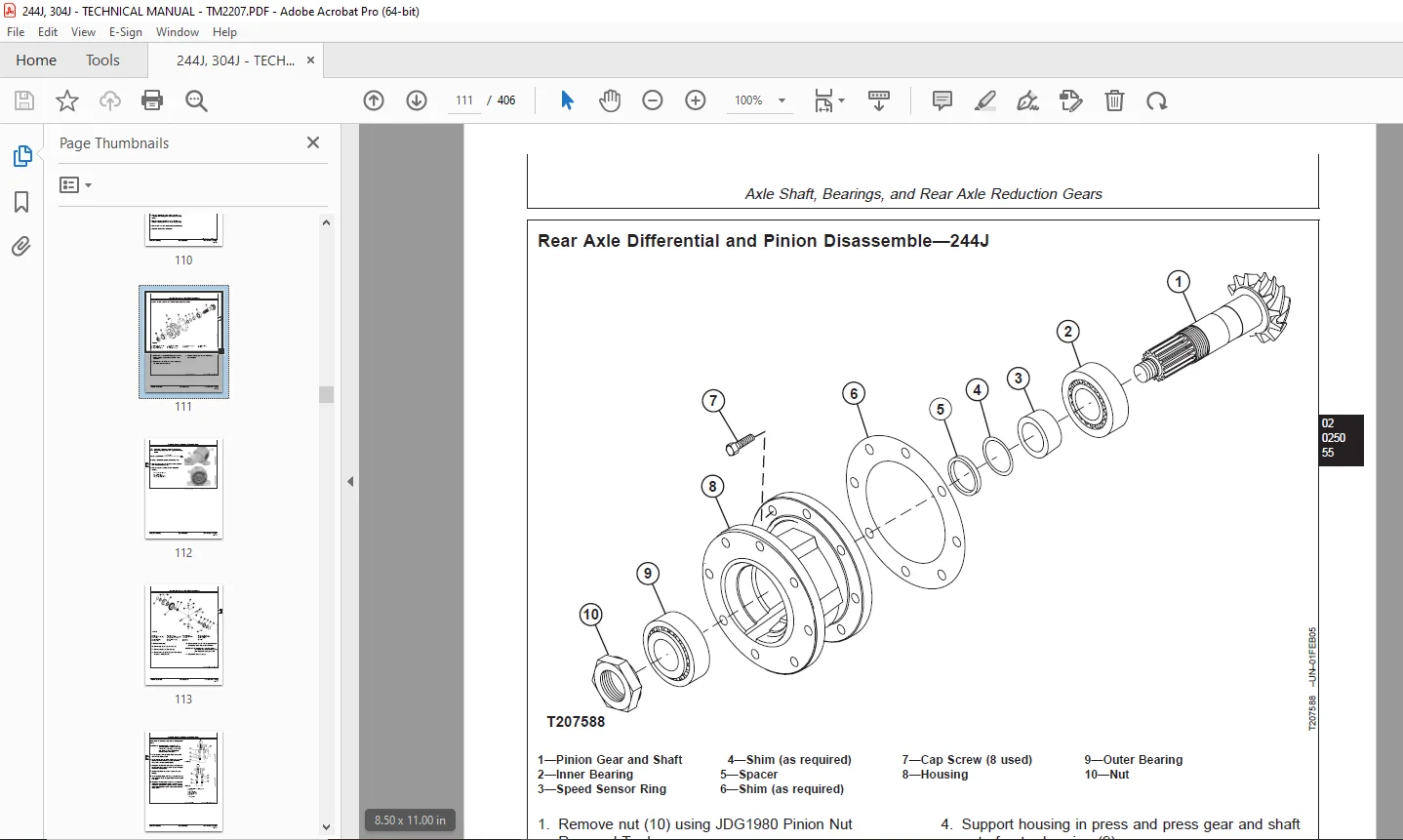
Rear Axle Differential and Pinion Disassemble—244J111
Rear Axle Differential and Pinion Assemble—244J114
Rear Axle Differential and Pinion Disassemble—304J125
Rear Axle Differential and Pinion Assemble—304J128
Rear Axle Reduction Gearbox Remove and Install137
Rear Axle Reduction Gearbox Disassemble and Assemble138
Transmission141
Hydrostatic Components Removal and Installation143
Hydrostatic Pump Valves Remove and Install143
Directional Control Valve Remove and Install147
Charge Pump Remove and Install148
Hydrostatic Pump Remove and Install152
Hydrostatic Motor Remove and Install154
Inching Valve Remove and Install157
Hydrostatic Start-Up Procedure158
Hydrostatic Components Repair159
Directional Control Valve Disassemble and Assemble159
Hydrostatic Pump Disassemble160
Hydrostatic Pump Assemble172
Hydrostatic Motor Control Valve O-Rings and Seals Remove and Install183
Hydrostatic Motor Flushing Valve O-Rings and Servo Piston Seals Remove and Install184
Hydrostatic Motor Disassemble186
Hydrostatic Motor Rotating Group Inspect and Recondition188
Hydrostatic Motor Assemble193
Engine195
Removal and Installation197
POWERTECH 24 L (4024) and 30 L (5030) John Deere Engines197
Serpentine Belt Remove and Install197
Engine Remove and Install197
Engine Auxiliary Systems205
Cooling System207
Hydraulic Cooling Fan Pump Remove and Install207
Hydraulic Cooling Fan Pump Disassemble and Assemble208
Cooling Fan and Cooling Fan Motor Remove and Install211
Cooling Fan Motor Disassemble and Assemble213
Radiator/Oil Cooler Remove and Install216
Speed Controls219
POWERTECH 24 L (4024) and 30 L (5030) John Deere Engines219
Speed Control Linkage Remove and Install219
External Fuel Supply Systems223
Fuel Tank Remove and Install223
Dampener Drive225
Removal and Installation227
Dampener Drive Remove and Install227
Steering System231
Hydraulic System233
Steering Valve Remove and Install233
Steering Valve Disassemble and Inspect234
Steering Valve Assemble240
Steering Column Remove and Install245
Steering Cylinder Remove and Install248
Steering Cylinder Disassemble and Assemble250
Service Brakes255
Active Elements257
Drum Brake Remove and Install257
Service Brakes (Wet Disk) Remove and Install258
Hydraulic System259
Brake/Inching Valve Assembly Remove and Install259
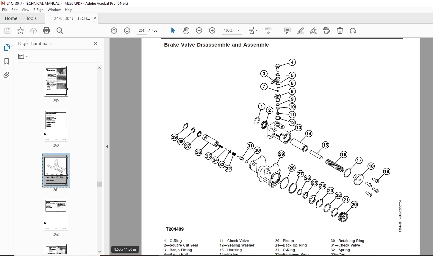
Brake Valve Disassemble and Assemble261
Drum Brake Bleed262
Park Brake265
Hydraulic System267
Park Brake Disassemble and Assemble267
Park Brake/Differential Lock Valve Block Remove and Install268
Frame or Supporting Structure271
Frame Installation273
Welding Repair of Major Structures273
Loader and Rear Frames Separation274
Rotational Torque Spring Remove and Install281
Upper Pivot Bushing Assembly Remove and Install282
Lower Pivot Bushing Assembly Remove and Install283
Chassis Weights285
Counterweights Remove and Install285
Operator’s Station287
Removal and Installation289
Cab Remove and Install289
Operator Enclosure297
Windowpanes Remove and Install297
Heating and Air Conditioning System299
Refrigerant Cautions and Proper Handling299
Flush and Purge Air Conditioner System301
R134a Refrigerant Oil Information304
R134a Refrigerant Recovery/Recycling and Charging Station Installation Procedure305
Recover R134a Refrigerant306
Evacuate R134a System307
Charge R134a System308
Air Conditioner Compressor Remove and Install309
Receiver-Dryer Remove and Install310
Condenser Remove and Install311
Air Conditioner/Heater Module Remove and Install312
Heater Core Remove and Install315
Evaporator Coil Remove and Install316
Expansion Valve Remove and Install317
Heater Control Valve Remove and Install318
AC High/Low Pressure Switch Remove and Install319
AC Thermostat Switch Remove and Install319
Blower Motor Remove and Install320
Sheet Metal and Styling321
Miscellaneous Shields323
Rear Fenders Remove and Install323
Main Hydraulic System325
Hydraulic System327
Hydraulic Oil Cleanup Procedure Using Portable Filter Caddy327
Main Hydraulic Pump/Priority Valve Remove and Install327
Main Hydraulic Pump/Priority Valve Disassemble and Assemble329
Hydraulic Reservoir Remove and Install333
Hydraulic Oil Cooler Remove and Install335
Loader337
Bucket339
Bucket Teeth Remove and Install339
Welded-On Bucket Cutting Edge Remove and Install340
Bolt-On Cutting Edge Remove and Install341
Cracked Cutting Edge Repair342
Attachment Coupler343
Quick Disconnect Hitch Disassemble and Assemble343
Frames353
Boom and Bucket Linkage Remove and Install353
Bucket Linkage Bushings Remove and Install356
Loader Boom Bushings Remove and Install358
Hydraulic System361
Loader Control Valve Remove and Install361
Loader Control Valve Disassemble and Assemble364
Auxiliary, Fourth Function, or Bucket Valve Section Disassemble and Assemble365
Boom Valve Section Disassemble and Assemble366
Loader System and Circuit Relief Valves Disassemble and Assemble367
Ride Control Valve Remove and Install—If Equipped368
Ride Control Valve Disassemble and Assemble—If Equipped370
Boom Cylinder Remove and Install371
Bucket Cylinder Remove and Install373
Boom and Bucket Cylinders Disassemble and Assemble374
Boom and Bucket Cylinder Bushings Remove and Install379
Pilot Control Valve Remove and Install380
Pilot Control Valve Disassemble and Assemble383
Quick Disconnect/Auxiliary Pilot Control Valve Remove and Install388
Quick Disconnect/Auxiliary Pilot Control Valve Disassemble and Assemble389
Pilot Lockout Solenoid Valve Remove and Install391
Pilot Accumulator Remove and Install393
Dealer Fabricated Tools395
Dealer Fabricated Tools397
DFT1214 Hydrostatic Pump Servo Piston Snap Ring Removal and Installation Tool397
DFT1254 304J Differential Bevel Gear Holding Tool398
DFT1255 304J Differential Bevel Gear Pin Installation Tool399
DESCRIPTION:
John Deere 244J and 304J Loaders Repair Technical Manual TM2207 – PDF DOWNLOAD
Foreword:
- This manual is written for an experienced technician. Essential tools required in performing certain service work are identified in this manual and are recommended for use. Live with safety: Read the safety messages in the introduction of this manual and the cautions presented throughout the text of the manual.
- This is the safety-alert symbol. When you see this symbol on the machine or in this manual, be alert to the potential for personal injury. Technical manuals are divided in two parts: repair and operation and tests. Repair sections tell how to repair the components. Operation and tests sections help you identify the majority of routine failures quickly.
- Information is organized in groups for the various components requiring service instruction. At the beginning of each group are summary listings of all applicable essential tools, service equipment and tools, other materials needed to do the job, service parts kits, specifications, wear tolerances, and torque values.
- Technical Manuals are concise guides for specific machines. They are on-the-job guides containing only the vital information needed for diagnosis, analysis, testing, and repair. Fundamental service information is available from other sources covering basic theory of operation, fundamentals of troubleshooting, general maintenance, and basic type of failures and their causes.
G.B 06/01/25