Trusted Business
Verified & Licensed
Virus Free Files
100% Safe Downloads
Secure Payment
SSL Protected
Instant Delivery
Available Immediately
John Deere 210LJ Landscape Loader Operation & Test Technical Manual TM10730 – PDF DOWNLOAD
$31.95
John Deere 210LJ Landscape Loader Operation & Test Technical Manual TM10730 – PDF DOWNLOAD
Instant PDF Download
Available immediately
Save to Your Device
Download & keep forever
Antivirus Scanned
100% virus-free
Trusted Worldwide
175,000+ customers
Description
John Deere 210LJ Landscape Loader Operation & Test Technical Manual TM10730 – PDF DOWNLOAD
FILE DETAILS:
John Deere 210LJ Landscape Loader Operation & Test Technical Manual TM10730 – PDF DOWNLOAD
Language : English
Pages : 683
Downloadable : Yes
File Type : PDF
IMAGES PREVIEW OF THE MANUAL:
TABLE OF CONTENTS:
John Deere 210LJ Landscape Loader Operation & Test Technical Manual TM10730 – PDF DOWNLOAD
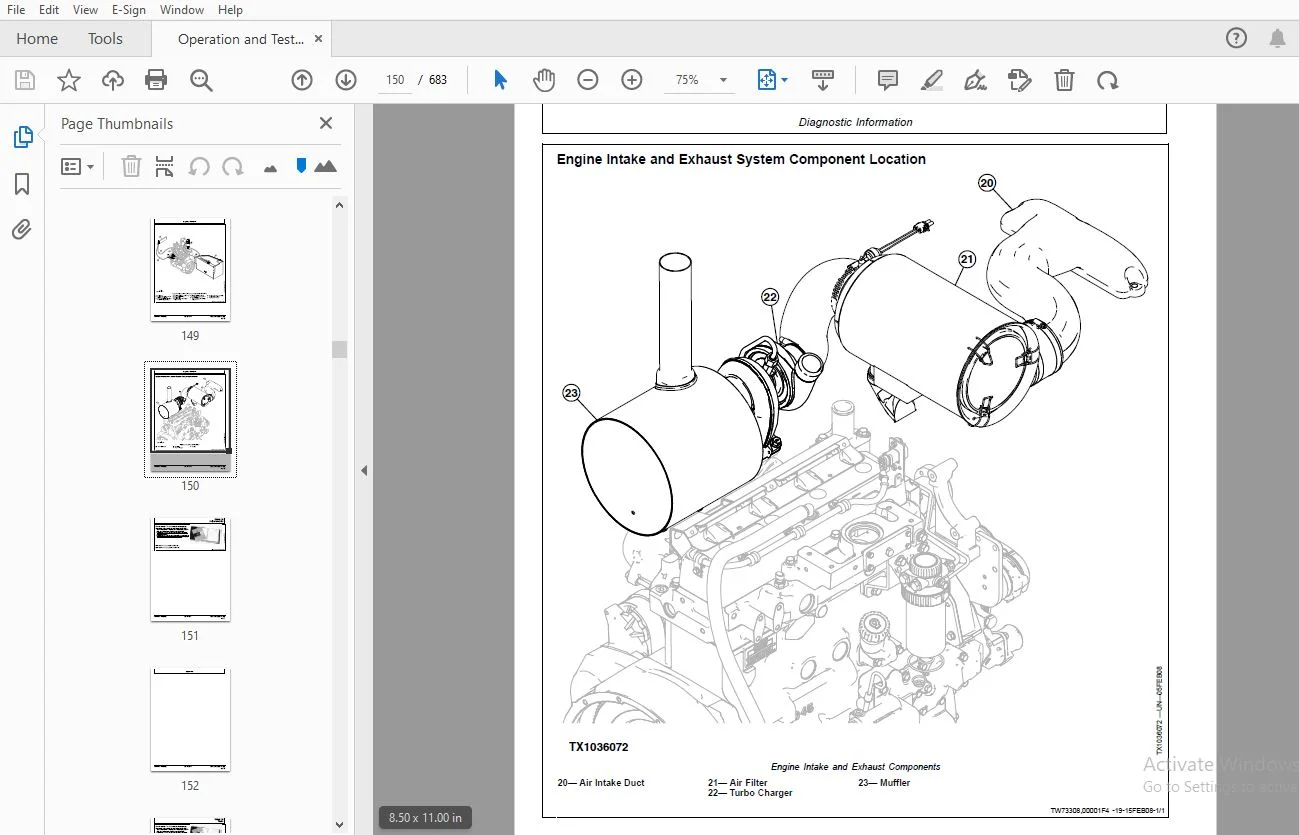
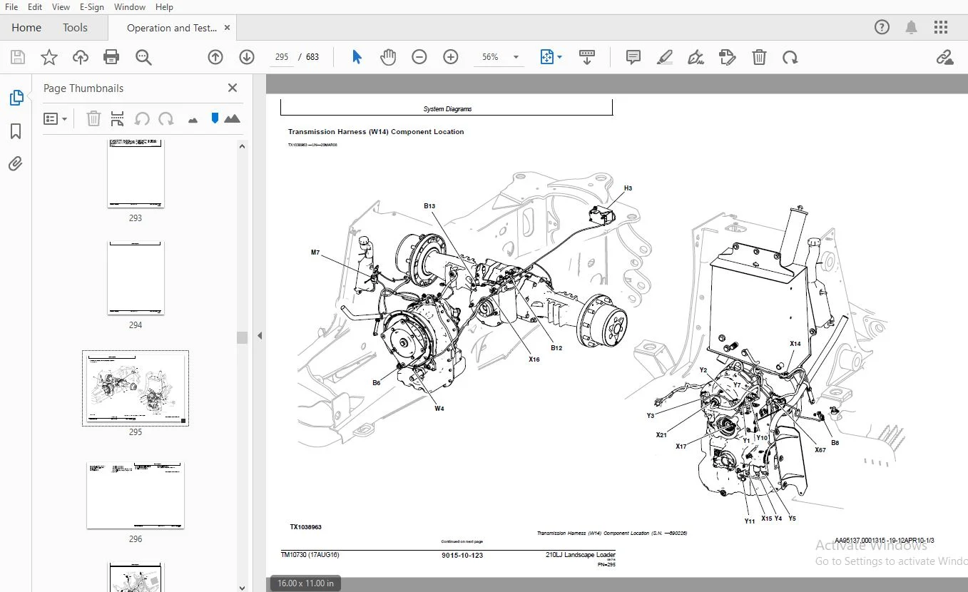
Contents.........................................................................................................  5
	General Information..........................................................................................  7
		Safety...................................................................................................  9
			Recognize Safety Information.........................................................................  9
			Follow Safety Instructions...........................................................................  9
			Operate Only If Qualified............................................................................  9
			Wear Protective Equipment............................................................................ 10
			Avoid Unauthorized Machine Modifications............................................................. 10
			Inspect Machine...................................................................................... 10
			Stay Clear of Moving Parts........................................................................... 10
			Avoid High-Pressure Fluids........................................................................... 11
			Avoid High-Pressure Oils............................................................................. 11
			Beware of Exhaust Fumes.............................................................................. 12
			Prevent Fires........................................................................................ 12
			Prevent Battery Explosions........................................................................... 12
			Handle Chemical Products Safely...................................................................... 13
			Dispose of Waste Properly............................................................................ 13
			Prepare for Emergencies.............................................................................. 13
			Use Steps and Handholds Correctly.................................................................... 13
			Start Only From Operator's Seat...................................................................... 14
			Use and Maintain Seat Belt........................................................................... 14
			Prevent Unintended Machine Movement.................................................................. 14
			Avoid Work Site Hazards.............................................................................. 15
			Keep Riders Off Machine.............................................................................. 15
			Avoid Backover Accidents............................................................................. 15
			Avoid Machine Tipover................................................................................ 16
			Add and Operate Attachments Safely................................................................... 16
			Use Special Care When Operating...................................................................... 17
			Operating or Traveling On Public Roads............................................................... 17
			Inspect and Maintain ROPS............................................................................ 17
			Stay Clear of Rotating Drivelines.................................................................... 18
			Park and Prepare for Service Safely.................................................................. 19
			Service Tires Safely................................................................................. 19
			Service Cooling System Safely........................................................................ 20
			Remove Paint Before Welding or Heating............................................................... 20
			Make Welding Repairs Safely.......................................................................... 20
			Drive Metal Pins Safely.............................................................................. 21
	Diagnostic Trouble Codes (DTC)............................................................................... 25
		Engine Control Unit (ECU) Diagnostic Trouble Codes....................................................... 27
			Engine Control Unit (ECU) Diagnostic Trouble Codes................................................... 27
			000029.03 — Hand Throttle Short to Power............................................................. 27
				Hand Throttle Short to Power Diagnostic Procedure................................................ 27
			000029.04 — Hand Throttle Open or Short.............................................................. 28
				Hand Throttle Open or Short Diagnostic Procedure................................................. 28
			000029.14 — Hand Throttle Out of Range............................................................... 29
				Hand Throttle Out of Range Diagnostic Procedure.................................................. 30
			000091.03 — Foot Throttle Short to Power............................................................. 30
				Foot Throttle Short to Power Diagnostic Procedure................................................ 30
			000091.04 — Foot Throttle Open or Short.............................................................. 31
				Foot Throttle Position Sensor Open or Short Diagnostic Procedure................................. 31
			000091.14 — Foot Throttle Sensor Out of Range........................................................ 33
				Foot Throttle Sensor Out of Range Diagnostic Procedure........................................... 34
			001075.05 — Fuel Transfer Pump Relay Open Circuit.................................................... 34
				Fuel Transfer Pump Relay Open Circuit Diagnostic Procedure....................................... 34
			001075.06 — Fuel Transfer Pump Relay Short to Ground................................................. 35
				Fuel Transfer Pump Relay Short to Ground Diagnostic Procedure.................................... 35
			001321.05 — Starter Relay Open Circuit............................................................... 36
				Starter Relay Open Circuit Diagnostic Procedure.................................................. 36
			001321.06 — Starter Relay Short to Ground............................................................ 37
				Starter Relay Short to Power..................................................................... 37
			001321.16 — Crank Cycle Too Long..................................................................... 38
				Crank Cycle Too Long Diagnostic Procedure........................................................ 39
			002023.09 — Hand Throttle Message Missing............................................................ 39
				Hand Throttle Message Missing Diagnostic Procedure............................................... 39
			523702.09 — Flex Power Message Missing............................................................... 40
				Flex Power Message Missing Diagnostic Procedure.................................................. 40
		Engagement and Monitor Unit (EMU) Diagnostic Trouble Codes............................................... 43
			Engagement and Monitor Unit (EMU) Diagnostic Trouble Codes........................................... 43
			000070.04 — Park Brake Switch Out of Range Low....................................................... 43
				Park Brake Switch Out of Range Low Diagnostic Procedure.......................................... 43
			000070.07 — Park Brake Switch Data Invalid........................................................... 44
				Park Brake Switch Data Invalid Diagnostic Procedure.............................................. 44
			000096.03 — Fuel Sensor Out of Range High............................................................ 45
				Fuel Sensor Out of Range High Diagnostic Procedure............................................... 45
			000096.04 — Fuel Sensor Out of Range Low............................................................. 47
				Fuel Sensor Out of Range Low Diagnostic Procedure................................................ 47
			000107.00 — Engine Air Filter Restricted............................................................. 49
				Engine Air Filter Restricted Diagnostic Procedure................................................ 49
			000158.00 — System Voltage Above Normal.............................................................. 51
				System Voltage Above Normal Diagnostic Procedure................................................. 51
			000158.16 — System Voltage High...................................................................... 51
				System Voltage High Diagnostic Procedure......................................................... 51
			000158.18 — System Voltage Low....................................................................... 52
				System Voltage Low Diagnostic Procedure.......................................................... 52
			000177.00 — Torque Converter Oil Temperature Too High................................................ 53
				Torque Converter Oil Temperature Too High Diagnostic Procedure................................... 53
			000177.03 — Torque Converter Oil Temperature Sensor Out of Range High................................ 54
				Torque Converter Oil Temperature Sensor Out of Range High Diagnostic Procedure................... 54
			000177.04 — Torque Converter Oil Temperature Sensor Out of Range Low................................. 56
				Torque Converter Oil Temperature Sensor Out of Range Low Diagnostic Procedure.................... 56
			000525.03 — Gear Switch Out of Range High............................................................ 58
				Gear Switch Out of Range High Diagnostic Procedure............................................... 58
			000525.04 — Gear Switch Out of Range Low............................................................. 59
				Gear Switch Out of Range Low Diagnostic Procedure................................................ 59
			000525.05 — Gear Switch Open Circuit................................................................. 60
				Gear Switch Open Circuit Diagnostic Procedure.................................................... 60
			000525.07 — Gear Switch Data Invalid................................................................. 62
				Gear Switch Data Invalid Diagnostic Procedure.................................................... 62
			000604.06 — FNR Supply Out of Range High............................................................. 63
				FNR Supply Out of Range High Diagnostic Procedure................................................ 63
			000736.06 — Y3 Solenoid Short to Ground.............................................................. 65
				Y3 Solenoid Short to Ground Diagnostic Procedure................................................. 65
			000736.12 — Y3 Solenoid Open or Short to Power....................................................... 66
				Y3 Solenoid Open or Short to Power Diagnostic Procedure.......................................... 66
			000737.06 — Y4 Solenoid Short to Ground.............................................................. 68
				Y4 Solenoid Short to Ground Diagnostic Procedure................................................. 68
			000737.12 — Y4 Solenoid Open or Short to Power....................................................... 70
				Y4 Solenoid Open or Short to Power Diagnostic Procedure.......................................... 70
			000738.06 — Y5 Solenoid Short to Ground.............................................................. 72
				Y5 Solenoid Short to Ground Diagnostic Procedure................................................. 72
			000738.12 — Y5 Solenoid Open or Short to Power....................................................... 73
				Y5 Solenoid Open or Short to Power Diagnostic Procedure.......................................... 73
			000767.02 — Reverse Switch Data Invalid.............................................................. 75
				Reverse Switch Data Invalid Diagnostic Procedure................................................. 75
			000767.05 — Reverse Switch Data Out of Range Low..................................................... 77
				Reverse Switch Data Out of Range Low Diagnostic Procedure........................................ 77
			000880.05 — Service Brake Lights Open Circuit........................................................ 78
				Service Brake Lights Open Circuit Diagnostic Procedure........................................... 78
			000903.02 — Forward Switch Data Invalid.............................................................. 79
				Forward Switch Data Invalid Diagnostic Procedure................................................. 79
			000903.05 — Forward Switch Data Out of Range Low..................................................... 81
				Forward Switch Data Out of Range Low Diagnostic Procedure........................................ 81
			000920.03 — Audible Alarm Open or Short to Power..................................................... 82
				Audible Alarm Open or Short to Power Diagnostic Procedure........................................ 82
			000920.04 — Audible Alarm Short to Ground............................................................ 83
				Audible Alarm Short to Ground Diagnostic Procedure............................................... 83
			001713.00 — Hydraulic Oil Filter Restricted.......................................................... 84
				Hydraulic Oil Filter Restricted Diagnostic Procedure............................................. 85
			002000.09 — CAN Communication Lost with ECU.......................................................... 86
				No CAN From ECU Diagnostic Procedure............................................................. 86
			298816.14 — Park Brake Data Invalid.................................................................. 87
				Park Brake Data Invalid Diagnostic Procedure..................................................... 87
			522379.03 — Park Brake Solenoid Short to Power....................................................... 88
				Park Brake Solenoid Short to Power Diagnostic Procedure.......................................... 88
			522379.05 — Park Brake Solenoid Open Circuit......................................................... 90
				Park Brake Solenoid Open Circuit Diagnostic Procedure............................................ 90
			522379.06 — Park Brake Solenoid Short to Ground...................................................... 91
				Park Brake Solenoid Short to Ground Diagnostic Procedure......................................... 91
			522398.14 — Park Brake Data Invalid.................................................................. 92
				Park Brake Data Invalid Diagnostic Procedure..................................................... 92
			522405.03 — Park Brake Pressure Switch Short to Power................................................ 94
				Park Brake Pressure Switch Short to Power Diagnostic Procedure................................... 94
			522411.02 — FNR Data Invalid......................................................................... 95
				FNR Data Invalid Data Invalid Diagnostic Procedure............................................... 95
			522411.03 — FNR Short to Power....................................................................... 96
				FNR Short to Power Diagnostic Procedure.......................................................... 97
			522411.05 — FNR Open Circuit......................................................................... 97
				FNR Open Circuit Diagnostic Procedure............................................................ 98
			522411.06 — FNR Short to Ground...................................................................... 99
				FNR Short to Ground Diagnostic Procedure......................................................... 99
			523702.02 — Flex Power ECU Watchdog Error............................................................100
				Flex Power ECU Watchdog Error Diagnostic Procedure...............................................100
			523702.07 — Flex Power Authentication Error..........................................................102
				Flex Power Authentication Error Diagnostic Procedure.............................................102
			523702.08 — Flex Power Inactive......................................................................103
				Flex Power Inactive Diagnostic Procedure.........................................................103
			523702.09 — Flex Power Status Message Not Received...................................................104
				Flex Power Status Message Not Received Diagnostic Procedure......................................104
			523702.10 — Flex Power Timeout With ECU..............................................................105
				Flex Power Timeout With ECU Diagnostic Procedure.................................................106
			524172.00 — Clutch Disconnect Switch Data Above Normal...............................................107
				Clutch Disconnect Switch Data Above Normal Diagnostic Procedure..................................107
			524172.03 — Clutch Disconnect Switch Out of Range High...............................................108
				Clutch Disconnect Switch Out of Range High Diagnostic Procedure..................................108
			524172.04 — Clutch Disconnect Switch Short to Ground.................................................109
				Clutch Disconnect Switch Short to Ground Diagnostic Procedure....................................110
	Operational Checkout Procedure...............................................................................113
		Operational Checkout Procedure...........................................................................115
			Operational Checkout.................................................................................115
				Diagnostic Trouble Codes.........................................................................115
				Key OFF, Engine Off Checks.......................................................................115
				Key ON, Engine Off Checks........................................................................117
				Key ON, Engine On Checks.........................................................................124
	Engine.......................................................................................................141
		Theory of Operation......................................................................................143
			PowerTech E™ 4.5 L John Deere Engines................................................................143
			Engine Cooling System................................................................................143
		Diagnostic Information...................................................................................145
			PowerTech E™ 4.5 L John Deere Engines................................................................145
			Engine Cooling System Component Location.............................................................145
			Engine Fuel System Component Location................................................................146
			Engine Intake and Exhaust System Component Location..................................................150
		Adjustments..............................................................................................151
			PowerTech E™ 4.5 L John Deere Engines................................................................151
		Tests....................................................................................................153
			PowerTech E™ 4.5 L John Deere Engines................................................................153
			Fluid Sampling Procedure—If Equipped.................................................................154
			JT05801 Clamp-On Electronic Tachometer Installation..................................................158
			Engine Speed Check...................................................................................158
			Air Intake System Leakage Test.......................................................................159
			Intake Manifold Pressure—Turbocharger Boost..........................................................160
			Injection Pump Timing................................................................................161
			Air in Fuel Test.....................................................................................161
			Engine Thermostat Test...............................................................................161
			Thermal Bypass Valve Test............................................................................161
	Electrical System............................................................................................164
		System Information.......................................................................................165
			Electrical Diagram Information.......................................................................165
			Electrical Schematic Symbols.........................................................................169
		System Diagrams..........................................................................................173
			Fuse and Relay Location and Specifications...........................................................173
			System Functional Schematic, Wiring Diagram, and Component Location Legend (S.N. —890226)............174
			System Functional Schematic and Section Legend (S.N. —890226)........................................177
			System Functional Schematic, Wiring Diagram, and Component Location Legend (S.N. 890227— )...........214
			System Functional Schematic and Section Legend (S.N. 890227— ).......................................217
			Load Center Harness (W11) Component Location.........................................................254
			Load Center Harness (W11) Wiring Diagram.............................................................259
			Front Console Harness (W12) Component Location.......................................................270
			Front Console Harness (W12) Wiring Diagram...........................................................275
			Engine Harness (W13) Component Location..............................................................283
			Engine Harness (W13) Wiring Diagram..................................................................287
			Transmission Harness (W14) Component Location........................................................295
			Transmission Harness (W14) Wiring Diagram............................................................299
			Canopy (ROPS) Harness (W15) Component Location.......................................................306
			Canopy (ROPS) Harness (W15) Wiring Diagram...........................................................307
			Cab Harness (W16) Component Location.................................................................310
			Cab Harness (W16) Wiring Diagram.....................................................................313
			Cab Roof Harness (W17) Component Location............................................................320
			Cab Roof Harness (W17) Wiring Diagram................................................................323
			Power Take-Off Harness (W18) Component Location—If Equipped..........................................326
			Power Take-Off Harness (W18) Wiring Diagram—If Equipped..............................................328
			Canopy 12-Volt Power Outlet Harness (W19) Component Location—If Equipped (S.N. —890226)..............330
			Canopy 12-Volt Power Outlet Harness (W19) Wiring Diagram—If Equipped (S.N. —890226)..................331
			Return-to-Dig Harness (W20) Component Location—If Equipped (S.N. —890226)............................332
			Return-to-Dig Harness (W20) Wiring Diagram—If Equipped (S.N. —890226)................................333
			Loader Coupler Harness (W21) Component Location—If Equipped (S.N. —890226)...........................334
			Loader Coupler Harness (W21) Wiring Diagram—If Equipped (S.N. —890226)...............................337
			Loader Coupler Harness (W21 and W22) Component Location—If Equipped (S.N. 890227— )..................340
			Loader Coupler Harness (W21 and W22) Wiring Diagram—If Equipped (S.N. 890227— )......................342
			Ride Control Harness (W23) Component Location—If Equipped (S.N. 890227— )............................344
			Ride Control Harness (W23) Wiring Diagram—If Equipped (S.N. 890227— )................................345
			Ride Control Harness (W23 and W24) Component Location—If Equipped (S.N. —890226).....................346
			Ride Control Harness (W23 and W24) Wiring Diagram—If Equipped (S.N. —890226).........................347
		Sub-System Diagnostics...................................................................................351
			Power Circuit Theory of Operation....................................................................351
			Start and Charge Circuits Theory of Operation........................................................355
			Controller Area Network (CAN) Theory of Operation....................................................360
			Engine Control Unit (ECU) Circuit Theory of Operation................................................363
			Engagement and Monitor Unit (EMU) Circuit Theory of Operation........................................371
			Transmission Control and Park Brake Circuits Theory of Operation.....................................377
			Power Take-Off (PTO) Circuit Theory of Operation—If Equipped.........................................388
		References...............................................................................................393
			Service ADVISOR™ Connection Procedure................................................................393
			Reading Diagnostic Trouble Codes (DTCs)..............................................................396
			Engagement and Monitor Unit (EMU) Menu Structure—Service Mode........................................399
			Anti-Theft Security System Enable and Disable........................................................401
			Anti-Theft Security System Configuration.............................................................402
			Alternator Test Procedure............................................................................404
			Electrical Component Specifications..................................................................405
			CAN Circuit Test.....................................................................................408
				Controller Area Network (CAN) Diagnostics .......................................................409
			Wire Harness Test....................................................................................412
			Sensor Circuit Check.................................................................................413
			Transmission Control Lever (TCL) Test................................................................414
			Transmission Solenoid Check..........................................................................414
			Engine Control Unit (ECU) Remove and Install.........................................................415
			Engagement and Monitor Unit (EMU) Remove and Install.................................................416
			Engagement and Monitor Unit (EMU) Initial Configuration..............................................417
			ReplaceWEATHER PACKWEATHER PACK is a trademark of Packard Electric™Connector.........................418
			Install WEATHER PACKWEATHER PACK is a trademark of Packard Electric™ Contact.........................419
			Replace DEUTSCHDEUTSCH is a trademark of Deutsch Co.™ Connectors.....................................420
			Replace DEUTSCHDEUTSCH is a trademark of Deutsch Co.™ Rectangular or Triangular Connectors...........421
			Install DEUTSCHDEUTSCH is a trademark of Deutsch Co.™ Contact........................................422
			Replace CINCHCINCH is a trademark of Cinch Inc.™ Connectors..........................................423
			Install CINCHCINCH is a trademark of Cinch Inc.™ Contact.............................................425
			Replace (Pull Type) METRI-PACKMETRI-PACK is a trademark of Packard Electric Inc.™ Connectors.........426
			Replace (PushType)METRI-PACKMETRI-PACK is a trademark of Packard Electric Inc.™ Connectors...........427
			Cinch CP Connector Assemble..........................................................................428
			Cinch CP Connector Terminal Removal..................................................................432
			Cinch CP Connector Terminal Hand Crimp Process.......................................................434
	Power Train..................................................................................................438
		Theory of Operation......................................................................................440
			Power Shift Power Train Overview.....................................................................440
			Clutch Modulation Operation..........................................................................442
			Torque Converter Operation...........................................................................444
			Transmission Pump Operation..........................................................................446
			Transmission Filter Operation........................................................................447
			Clutch and Mechanical Front Wheel Drive (MFWD) Operation.............................................448
			Power Shift Transmission Gear Flow...................................................................450
			Power Shift Transmission Clutch Engagement And Solenoids Activated...................................453
			Differential Operation...............................................................................454
			Differential Lock Operation..........................................................................456
			MICO Power Boost Brake Valve—Neutral Position........................................................458
			MICO Power Boost Brake Valve—Both Pedals Applied Position............................................459
			MICO Power Boost Brake Valve—One Pedal Applied Position..............................................460
			MICO Power Boost Brake Valve—Both Pedals Applied, Engine Off Position................................461
			Service Brake Operation..............................................................................462
			Park Brake Operation.................................................................................464
			MFWD Differential Operation—Unequal Traction.........................................................466
			MFWD Differential Operation—Equal Traction...........................................................467
		Diagnostic Information...................................................................................469
			Power Train Component Location.......................................................................469
			Power Train Schematic—Neutral........................................................................473
			Power Train Schematic—First Forward Mechanical Front Wheel Drive (MFWD) Engaged......................477
			Power Train Schematic—First Reverse..................................................................481
			Power Train Schematic—Fourth Forward.................................................................485
			Diagnose Transmission Malfunctions...................................................................488
			Transmission Slippage................................................................................488
				Transmission Slippage Diagnostic Procedure.......................................................489
			Machine Lacks Power or Moves Slow....................................................................489
				Machine Lacks Power or Moves Slow Diagnostic Procedure...........................................489
			Transmission Overheats...............................................................................492
				Transmission Overheats Diagnostic Procedure......................................................492
			Excessive Power Train Noise..........................................................................494
				Excessive Power Train Noise Diagnostic Procedure.................................................494
			Park Brake Piston Leak...............................................................................496
				Excessive Power Train Noise Diagnostic Procedure.................................................496
			No Power to Mechanical Front Wheel Drive (MFWD)......................................................496
				No Power to Mechanical Front Wheel Drive (MFWD) Diagnostic Procedure.............................496
			No Power to One Wheel of Mechanical Front Wheel Drive (MFWD).........................................498
				No Power to One Wheel of Mechanical Front Wheel Drive (MFWD) Diagnostic Procedure................498
			No Differential Lock Operation.......................................................................499
				No Differential Lock Operation Diagnostic Procedure..............................................499
			Differential Lock Slips or Chatters When Engaged.....................................................499
				Differential Lock Slips or Chatters When Engaged Diagnostic Procedure............................499
			Differential Lock Will Not Release...................................................................500
				Differential Lock Will Not Release Diagnostic Procedure..........................................500
			Rear Axle Overfilled With Oil........................................................................502
				Rear Axle Overfilled With Oil Diagnostic Procedure...............................................502
			Poor Service Brakes..................................................................................503
				Poor Service Brakes Diagnostic Procedure.........................................................503
			Service Brakes Will Not Release......................................................................504
				Service Brakes Will Not Release Diagnostic Procedure.............................................504
			Service Brakes Chatter or Noisy......................................................................504
				Service Brakes Chatter or Noisy Diagnostic Procedure.............................................505
			Park Brake Will Not Hold.............................................................................505
				Park Brake Will Not Hold Diagnostic Procedure....................................................505
			Park Brake Will Not Release..........................................................................506
				Park Brake Will Not Release Diagnostic Procedure.................................................506
		Adjustments..............................................................................................509
			Brake Pedal Adjustment...............................................................................509
			Brake System Bleeding Procedure......................................................................510
			Park Brake Release for Towing........................................................................512
			Tracking Angle Check and Adjust......................................................................513
			Toe-In Check and Adjust..............................................................................513
			Steering Angle Check and Adjust—MFWD Axle............................................................514
		Tests....................................................................................................515
			Transmission Oil Warmup Procedure....................................................................515
			Power Shift Transmission Overall Test Connections, Ports, and Locations..............................516
			Torque Converter Stall Speed Test....................................................................518
			Torque Converter Inlet Pressure Test.................................................................519
			Brake Valve Leakage Test.............................................................................521
			Park Brake Release Pressure Test.....................................................................522
			Transmission System Pressure Test....................................................................524
			Clutch Pressure Test.................................................................................525
			Differential Lock Pressure Test......................................................................526
			Mechanical Front Wheel Drive (MFWD) Pressure Test....................................................527
			Cooler In and Cooler Out Pressure Test...............................................................528
			Solenoid Circuit Leakage Test........................................................................529
			Transmission Pump Flow Test..........................................................................530
	Hydraulic System.............................................................................................532
		Theory of Operation......................................................................................533
			Open-Center Hydraulic System Operation...............................................................533
			Hydraulic Pump Operation.............................................................................534
			Hydraulic Filter Operation...........................................................................535
			Steering Valve Operation.............................................................................536
			Priority Valve Section Operation—Steering Actuated...................................................540
			Ride Control Hydraulic Circuit and Valve Operation...................................................542
			Relief Valve Operation with Anticavitation...........................................................543
			Relief Valve Operation without Anticavitation........................................................544
			Control Valve—Inlet Section with System Relief Valve.................................................545
			Control Valve—Bucket Section—Dump....................................................................546
			Control Valve—Boom Section—Raise.....................................................................548
			Control Valve—Flow Control Section...................................................................550
			Control Valve—Boom Section—Float.....................................................................552
			Control Valve—Hitch Pitch Section....................................................................554
			Control Valve—Hitch Lift Section—Raise...............................................................556
			Control Valve—Hitch Tilt and Auxiliary Sections......................................................558
			Loader Coupler Hydraulic Operation...................................................................559
		Diagnostic Information...................................................................................561
			Hydraulic System Schematic...........................................................................561
			Hydraulic System Component Location..................................................................565
			Hydraulic Control Valve Component Location...........................................................573
			No Loader, Hitch, or Steering Hydraulics.............................................................573
				No Loader, Hitch or Steering Hydraulics Diagnostic Procedure.....................................573
			No Loader and Hitch Hydraulics (Steering OK).........................................................574
				No Loader and Hitch Hydraulics (Steering OK) Diagnostic Procedure................................574
			Slow Steering Hydraulics.............................................................................575
				Slow Steering Hydraulics Diagnostic Procedure....................................................575
			No Steering Hydraulics (Control Valve and Hitch Hydraulics OK).......................................575
				No Steering Hydraulics (Control Valve and Hitch Hydraulics OK) Diagnostic Procedure..............576
			Engine Pulls Down Excessively During Control Valve Operation.........................................576
				Engine Pulls Down Excessively During Control Valve Operation Diagnostic Procedure................576
			Slow Hydraulic Functions.............................................................................576
				Slow Hydraulic Functions Diagnostic Procedure....................................................576
			Loader or Hitch Operates Slowly in One Function......................................................577
				Loader or Hitch Operates Slowly in One Function Diagnostic Procedure.............................577
			No Loader or Hitch Power in One Function.............................................................578
				No Loader or Hitch Power in One Function Diagnostic Procedure....................................578
			Slow Loader and Hitch Hydraulics (Low Pump Output)...................................................579
				Slow Loader and Hitch Hydraulics (Low Pump Output) Diagnostic Procedure..........................579
			No or Slow Hitch Hydraulics (Loader Hydraulics OK)...................................................580
				No or Slow Hitch Hydraulics (Loader Hydraulics OK) Diagnostic Procedure..........................580
			Low Hydraulic Power (Low Hydraulic Pressure).........................................................580
				Low Hydraulic Power (Low Hydraulic Pressure).....................................................580
			Hydraulic Function Makes "Chattering" Noise..........................................................581
				Hydraulic Function Makes "Chattering" Noise Diagnostic Procedure.................................581
			Functions Drift......................................................................................582
				Functions Drift Diagnostic Procedure.............................................................582
			Control Valve Sticks or Works Hard...................................................................583
				Control Valve Sticks or Works Hard Diagnostic Procedure..........................................583
			Hydraulic Oil Overheats..............................................................................584
				Hydraulic Oil Overheats Diagnostic Procedure.....................................................584
			Foaming Oil..........................................................................................585
				Foaming Oil Diagnostic Procedure.................................................................585
			Hydraulic Pump Leaking...............................................................................586
				Hydraulic Pump Leaking Diagnostic Procedure......................................................586
			Excessive Pump Noise.................................................................................587
				Excessive Pump Noise Diagnostic Procedure........................................................587
			Steering Valve Does Not Return to Neutral............................................................588
				Steering Valve Does Not Return to Neutral Diagnostic Procedure...................................588
			No Response when Steering Wheel Is Turned............................................................588
				No Response when Steering Wheel Is Turned Diagnostic Procedure...................................588
			Machine Turns in Opposite Direction..................................................................589
				Machine Turns in Opposite Direction Diagnostic Procedure.........................................589
			Machine Turns when Steering Valve is in Neutral......................................................590
				Machine Turns when Steering Valve is in Neutral Diagnostic Procedure.............................590
			Steering Wheel Kickback..............................................................................590
				Steering Wheel Kickback Diagnostic Procedure.....................................................590
			Loader Coupler Not Working...........................................................................590
				Loader Coupler Not Working Diagnostic Procedure..................................................590
		Adjustments..............................................................................................593
			Loader Bucket Self-Leveling Linkage and Return-to-Dig Switch Adjustment..............................593
			Ride Control Accumulator Charge Procedure............................................................596
			Ride Control Accumulator Charge Check Procedure......................................................598
			Ride Control Accumulator Discharge Procedure.........................................................599
		Tests....................................................................................................601
			Hydraulic Oil Warmup Procedure.......................................................................601
			JT02156A Digital Pressure And Temperature Analyzer Kit Installation..................................601
			Hydraulic Circuit Pressure Release Procedure.........................................................601
			Hydraulic Pump Flow Test.............................................................................602
			Steering Load Sense Relief Valve Pressure Test.......................................................603
			System Relief Valve Pressure Test....................................................................604
			Hydraulic Oil Cooler Restriction Test................................................................605
			Circuit Relief Valve Test—With Remote Pump...........................................................607
			Steering System Leakage Test.........................................................................609
			Steering Cylinder Leakage Test.......................................................................611
			Function Drift Test..................................................................................612
			Hydraulic Cylinder Leakage Test......................................................................613
	Hydrostatic PTO System.......................................................................................615
		Theory of Operation......................................................................................617
			Hydrostatic PTO System Operation.....................................................................617
			Hydrostatic PTO Pump Operation.......................................................................619
			Hydrostatic PTO Pump Control Circuit Operation—Actuated..............................................622
			Hydrostatic PTO High Pressure Relief Valve Operation.................................................624
			Hydrostatic PTO Motor Operation......................................................................625
		Diagnostic Information...................................................................................628
			Hydrostatic PTO System Schematic.....................................................................628
			Hydrostatic PTO System Component Location............................................................631
			PTO Does Not Operate.................................................................................633
				PTO Does Not Operate Diagnostic Procedure........................................................633
			PTO Operates Erratically.............................................................................634
				PTO Operates Erratically Diagnostic Procedure....................................................634
			PTO Rotates in Wrong Direction.......................................................................634
				PTO Rotates in Wrong Direction Diagnostic Procedure..............................................635
			PTO Does Not Go To or Stay in Neutral................................................................635
				PTO Does Not Go To or Stay in Neutral Diagnostic Procedure.......................................635
			Hydraulic Oil Overheats During PTO Operation.........................................................635
				Hydraulic Oil Overheats During PTO Operation Diagnostic Procedure................................635
			PTO Lacks Power or Is Sluggish.......................................................................636
				PTO Lacks Power or Is Sluggish Diagnostic Procedure..............................................636
			Excessive Noise from PTO System (Under Load or No Load)..............................................637
				Excessive Noise from PTO System (Under Load or No Load) Diagnostic Procedure.....................637
		Adjustments..............................................................................................639
			Hydrostatic PTO Pump Servo Piston Neutral Adjustment.................................................639
		Tests....................................................................................................641
			Hydrostatic PTO Pump Neutral Charge Relief Valve Pressure Test and Adjustment........................641
			Hydrostatic PTO Pump High Pressure Relief Valve and Pressure Override Valve Tests and Adjustments....643
			PTO Oil Cooler Restriction Test......................................................................647
	Heating and Air Conditioning.................................................................................649
		Theory of Operation......................................................................................651
			Air Conditioning System Cycle Of Operation...........................................................651
		Diagnostic Information...................................................................................653
			Air Conditioning System Does Not Operate.............................................................653
				Air Conditioning System Does Not Operate Diagnostic Procedure....................................653
			Air Conditioner Does Not Cool Interior of Cab........................................................654
				Air Conditioner Does Not Cool Interior of Cab Diagnostic Procedure...............................654
			Air Conditioning Runs Constantly, Too Cold...........................................................656
				Air Conditioning Runs Constantly, Too Cold Diagnostic Procedure..................................656
			Interior Windows Continue to Fog.....................................................................657
				Interior Windows Continue to Fog Diagnostic Procedure............................................657
			Heater System Does Not Operate.......................................................................657
				Heater System Does Not Operate Diagnostic Procedure..............................................657
			Heater Does Not Warm Interior of Cab.................................................................658
				Heater Does Not Warm Interior of Cab Diagnostic Procedure........................................658
			Air Conditioning and Heater System Component Location................................................661
		Tests....................................................................................................665
			Refrigerant Cautions and Proper Handling.............................................................665
			Refrigerant Leak Test................................................................................665
			Blower Switch Test...................................................................................666
			Blower Resistor Test.................................................................................666
			Blower Motor Test....................................................................................667
			Air Conditioning On/Off Switch Test..................................................................667
			Air Conditioning Compressor Clutch Test..............................................................667
			Air Conditioning Binary Pressure Switch Test.........................................................668
			Air Conditioning Freeze Control Switch Test..........................................................669
			R134a Air Conditioning System Test...................................................................670
			Operating Pressure Diagnostic Chart..................................................................672
Page Number......................................................................................................  5
	Section 9000.................................................................................................  7
		Group 01.................................................................................................  9
	Section 9001................................................................................................. 25
		Group 10................................................................................................. 27
		Group 20................................................................................................. 43
	Section 9005.................................................................................................113
		Group 10.................................................................................................115
	Section 9010.................................................................................................141
		Group 05.................................................................................................143
		Group 15.................................................................................................145
		Group 20.................................................................................................151
		Group 25.................................................................................................153
	Section 9015.................................................................................................164
		Group 05.................................................................................................165
		Group 10.................................................................................................173
		Group 15.................................................................................................351
		Group 20.................................................................................................393
	Section 9020.................................................................................................438
		Group 05.................................................................................................440
		Group 15.................................................................................................469
		Group 20.................................................................................................509
		Group 25.................................................................................................515
	Section 9025.................................................................................................532
		Group 05.................................................................................................533
		Group 15.................................................................................................561
		Group 20.................................................................................................593
		Group 25.................................................................................................601
	Section 9026.................................................................................................615
		Group 05.................................................................................................617
		Group 15.................................................................................................628
		Group 20.................................................................................................639
		Group 25.................................................................................................641
	Section 9031.................................................................................................649
		Group 05.................................................................................................651
		Group 15.................................................................................................653
		Group 25.................................................................................................665
DESCRIPTION:
John Deere 210LJ Landscape Loader Operation & Test Technical Manual TM10730 – PDF DOWNLOAD
- This manual is written for an experienced technician. Essential tools required in performing certain service work are identified in this manual and are recommended for use.
- Live with safety: Read the safety messages in the introduction of this manual and the cautions presented throughout the text of the manual.
- Technical manuals are divided in two parts: repair and operation and tests. Repair sections tell how to repair the components. Operation and tests sections help you identify the majority of routine failures quickly.
- Information is organized in groups for the various components requiring service instruction. At the beginning of each group are summary listings of all applicable essential tools, service equipment and tools, other materials needed to do the job, service parts kits, specifications, wear tolerances, and torque values.
- Technical Manuals are concise guides for specific machines. They are on-the-job guides containing only the vital information needed for diagnosis, analysis, testing, and repair.
- Fundamental service information is available from other sources covering basic theory of operation, fundamentals of troubleshooting, general maintenance, and basic type of failures and their causes
S.S 17/02/2025