Trusted Business
Verified & Licensed
Virus Free Files
100% Safe Downloads
Secure Payment
SSL Protected
Instant Delivery
Available Immediately
John Deere 210LE Landscape Loader Repair Technical Manual TM1692 – PDF DOWNLOAD
$31.95
John Deere 210LE Landscape Loader Repair Technical Manual TM1692 – PDF DOWNLOAD
Instant PDF Download
Available immediately
Save to Your Device
Download & keep forever
Antivirus Scanned
100% virus-free
Trusted Worldwide
175,000+ customers
Description
John Deere 210LE Landscape Loader Repair Technical Manual TM1692 – PDF DOWNLOAD
FILE DETAILS:
John Deere 210LE Landscape Loader Repair Technical Manual TM1692 – PDF DOWNLOAD
Language : English
Pages : 624
Downloadable : Yes
File Type : PDF
IMAGES PREVIEW OF THE MANUAL:
TABLE OF CONTENTS:
John Deere 210LE Landscape Loader Repair Technical Manual TM1692 – PDF DOWNLOAD
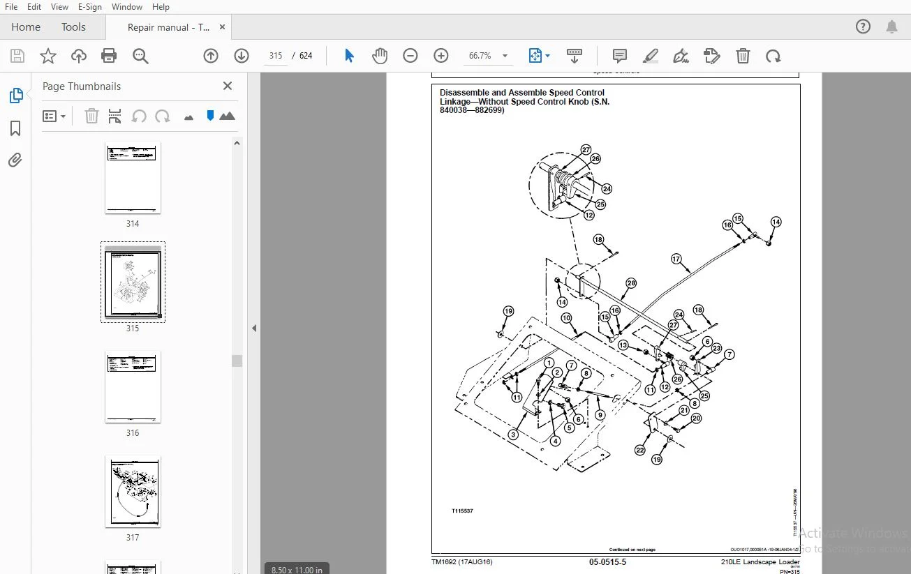
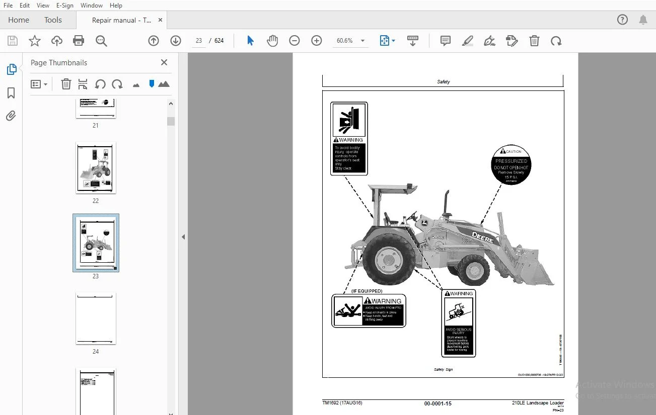
Contents....................................................................................................................  5
	General Information.....................................................................................................  7
		Safety..............................................................................................................  9
			Safety Features.................................................................................................  9
			Recognize Safety Information.................................................................................... 10
			Follow Safety Instructions...................................................................................... 10
			Operate Only If Qualified....................................................................................... 10
			Wear Protective Equipment....................................................................................... 11
			Avoid Unauthorized Machine Modifications........................................................................ 11
			Inspect Machine................................................................................................. 11
			Stay Clear of Moving Parts...................................................................................... 11
			Avoid High-Pressure Fluids...................................................................................... 12
			Beware of Exhaust Fumes......................................................................................... 12
			Prevent Fires................................................................................................... 13
			Prevent Battery Explosions...................................................................................... 13
			Handle Chemical Products Safely................................................................................. 13
			Dispose of Waste Properly....................................................................................... 14
			Prepare for Emergencies......................................................................................... 14
			Use Steps and Handholds Correctly............................................................................... 14
			Start Only From Operator's Seat................................................................................. 14
			Use and Maintain Seat Belt...................................................................................... 15
			Prevent Unintended Machine Movement............................................................................. 15
			Avoid Work Site Hazards......................................................................................... 15
			Keep Riders Off Machine......................................................................................... 16
			Avoid Backover Accidents........................................................................................ 16
			Avoid Machine Tipover........................................................................................... 17
			Add and Operate Attachments Safely.............................................................................. 17
			Use Special Care When Operating................................................................................. 18
			Operating or Traveling On Public Roads.......................................................................... 18
			Inspect and Maintain ROPS....................................................................................... 18
			Stay Clear of Rotating Drivelines............................................................................... 19
			Park and Prepare for Service Safely............................................................................. 20
			Service Cooling System Safely................................................................................... 20
			Remove Paint Before Welding or Heating.......................................................................... 21
			Make Welding Repairs Safely..................................................................................... 21
			Drive Metal Pins Safely......................................................................................... 21
			Safety Sign..................................................................................................... 22
	Wheels.................................................................................................................. 25
		Powered or Non-Powered Wheels and Fastenings........................................................................ 27
			Service Equipment and Tools..................................................................................... 27
			Specifications.................................................................................................. 27
			Remove and Install Rear Wheel Assembly.......................................................................... 28
			Remove and Install Front Wheel Assembly......................................................................... 29
			Remove and Install Tire......................................................................................... 30
	Axles and Suspension Systems............................................................................................ 33
		Input Drive Shafts and U-Joints..................................................................................... 35
			Specifications.................................................................................................. 35
			Remove and Install Drive Shaft.................................................................................. 35
			Replace Drive Shaft U-Joints.................................................................................... 35
		Non-Powered Wheel Axles............................................................................................. 37
			Service Equipment and Tools..................................................................................... 37
			Other Material.................................................................................................. 37
			Specifications.................................................................................................. 37
			Remove and Install Hub Assembly................................................................................. 38
			Hub Assembly Remove and Install (Carraro Replacement Axle)...................................................... 40
			Remove and Install Spindle and Knuckle Assembly................................................................. 41
			Spindle Assembly Remove and Install (Carraro Replacement Axle).................................................. 42
			Tie Rod Remove and Install...................................................................................... 45
			Remove and Install Non-Powered Front Axle....................................................................... 46
			Non-Powered Front Axle Remove and Install (Carraro Replacement Axle)............................................ 47
		Powered Wheel Axle (MFWD)........................................................................................... 49
			Front Wheel Drive Axles—AS and MS Series........................................................................ 49
			Service Equipment and Tools..................................................................................... 49
			Other Material.................................................................................................. 49
			Specifications.................................................................................................. 49
			Remove and Install Powered Front Axle—If Equipped............................................................... 50
		Axle Shaft, Bearings, and Reduction Gears........................................................................... 53
			Essential Tools................................................................................................. 53
			Service Equipment and Tools..................................................................................... 53
			Other Material.................................................................................................. 54
			Specifications.................................................................................................. 55
			Remove and Install Rear Axle.................................................................................... 56
			Disassemble Rear Axle........................................................................................... 57
			Disassemble and Assemble Park Brake (S.N. —881365).............................................................. 66
			Disassemble and Assemble Park Brake (S.N. 881366— )............................................................. 83
			Assemble Rear Axle..............................................................................................100
			Check Gear Tooth Contact Pattern................................................................................119
	Transmission............................................................................................................122
		Removal and Installation............................................................................................123
			Specifications..................................................................................................123
			Remove and Install Transmission.................................................................................123
		Controls Linkage....................................................................................................131
			Other Material..................................................................................................131
			Specifications..................................................................................................131
			Remove and Install Transmission Gearshift Lever.................................................................131
			Remove Shift Lever and Housing..................................................................................134
			Disassemble and Assemble Shift Lever and Housing................................................................136
			Install Shift Lever and Housing.................................................................................139
		Gears, Shafts, Bearings, and Power Shift Clutch.....................................................................141
			Essential Tools.................................................................................................141
			Service Equipment and Tools.....................................................................................141
			Other Material..................................................................................................142
			Specifications..................................................................................................143
			Remove Outer Components to Disassemble Manual Shift Transmission................................................144
			Disassemble Converter Side of Case—Manual Shift.................................................................148
			Remove Oil Suction Tube—Manual Shift............................................................................151
			Remove Reverse and Forward Clutch Packs—Manual Shift............................................................151
			Disassemble and Assemble Reverse or Forward Clutch Pack—Manual Shift............................................151
			Remove Drive Shaft—Manual Shift.................................................................................161
			Disassemble and Assemble Drive Shaft—Manual Shift...............................................................161
			Remove Rear Output Shaft with Synchronizer—Manual Shift.........................................................163
			Remove Intermediate Shaft with Synchronizer—Manual Shift........................................................164
			Disassemble Rear Output or Intermediate Shaft with Synchronizer—Manual Shift....................................164
			Rear Output Shaft—Cross Section View—Manual Shift...............................................................168
			Intermediate Shaft—Cross Section View—Manual Shift..............................................................169
			Assemble Rear Output or Intermediate Shaft—Manual Shift.........................................................169
			Remove MFWD Output Shaft—Manual Shift...........................................................................175
			Disassemble MFWD Shaft—Manual Shift.............................................................................175
			MFWD Shaft—Cross Section View—Manual Shift......................................................................178
			Assemble MFWD Shaft—Manual Shift................................................................................179
			Remove, Disassemble, and Assemble Idler Shaft—Manual Shift......................................................181
			Remove and Install Oil Supply Tube—Manual Shift.................................................................182
			Install Idler and MFWD Shafts to Assemble Transmission—Manual Shift.............................................182
			Install Intermediate and Rear Output Shafts—Manual Shift........................................................185
			Install Drive Shaft—Manual Shift................................................................................186
			Install Forward and Reverse Clutch Packs—Manual Shift...........................................................187
			Install Oil Suction Tube—Manual Shift...........................................................................188
			Assemble Converter Side of Case—Manual Shift....................................................................189
			Install Outer Components to Assemble Transmission—Manual Shift..................................................192
			Remove Outer Components to Disassemble Power Shift Transmission.................................................198
			Disassemble Converter Side of Case—Power Shift..................................................................200
			Remove Low Range Forward, Reverse and Third Speed Clutch Packs—Power Shift......................................202
			Disassemble and Assemble Low Range Forward, Reverse and Third Speed Clutch Packs—Power Shift....................203
			Remove First Speed, Second Speed, and High Range Forward Clutch Packs—Power Shift...............................213
			Disassemble and Assemble First Speed, Second Speed, and High Range Forward Clutch Packs—Power Shift.............213
			Remove Drive Shaft—Power Shift..................................................................................224
			Disassemble and Assemble Drive Shaft—Power Shift................................................................224
			Remove MFWD Output Shaft—Power Shift............................................................................226
			Disassemble MFWD Shaft—Power Shift..............................................................................228
			Assemble MFWD Shaft—Power Shift.................................................................................230
			Remove Oil Suction Tube—Power Shift.............................................................................232
			Remove and Install Oil Supply Tubes—Power Shift.................................................................233
			Install Oil Suction Tube—Power Shift............................................................................234
			Install MFWD Shaft to Assemble Transmission—Power Shift ........................................................234
			Install Drive Shaft—Power Shift.................................................................................235
			Install Clutch Packs—Power Shift................................................................................236
			Assemble Converter Side of Case—Power Shift.....................................................................237
			Install Outer Components to Assemble Transmission—Power Shift...................................................241
		Hydraulic System....................................................................................................247
			Other Material..................................................................................................247
			Specifications..................................................................................................247
			Remove and Install Control Valve—Manual Shift...................................................................248
			Disassemble and Assemble Control Valve—Manual Shift.............................................................248
			Remove and Install Transmission Charge Pump—Manual Shift........................................................257
			Remove and Install Transmission Charge Pump—Power Shift.........................................................258
			Disassemble and Assemble Transmission Charge Pump—Manual Shift and Power Shift..................................258
			Remove and Install Manifold Plate and Solenoids—Manual Shift....................................................262
			Remove and Install Control Valve—Power Shift....................................................................264
			Disassemble and Assemble Control Valve—Power Shift..............................................................265
			Remove and Install Shift Valve—Power Shift......................................................................274
			Disassemble and Assemble Shift Valve—Power Shift................................................................275
			Remove and Install Manifold Plate and Solenoids—Power Shift.....................................................280
	Engine..................................................................................................................283
		Removal and Installation............................................................................................285
			POWERTECH 4.5L (4045) and 6.8L (6068) John Deere Engines........................................................285
			Essential Tools.................................................................................................285
			Specifications..................................................................................................286
			Remove and Install Engine.......................................................................................286
	Engine Auxiliary Systems................................................................................................297
		Cold Weather Starting Aid...........................................................................................299
			Specifications..................................................................................................299
			Remove and Install Coolant Heater...............................................................................299
			Remove and Install Starting Aid Nozzle..........................................................................300
			Remove and Install Starting Aid Solenoid (S.N. —882699).........................................................302
			Remove and Install Starting Aid Solenoid (S.N. 882700— )........................................................303
		Cooling Systems.....................................................................................................305
			Service Equipment and Tools.....................................................................................305
			Specifications..................................................................................................305
			Remove and Install Fan..........................................................................................305
			Remove and Install Fan Belt.....................................................................................306
			Remove and Install Radiator (S.N. —882699)......................................................................307
			Remove and Install Radiator (S.N. 882700— ).....................................................................309
		Speed Controls......................................................................................................311
			Disassemble and Assemble Speed Control Linkage—With Speed Control Knob (S.N. —872334)...........................311
			Disassemble and Assemble Speed Control Linkage—With Speed Control Knob (S.N. 872335—882699).....................313
			Disassemble and Assemble Speed Control Linkage—Without Speed Control Knob (S.N. 840038—882699)..................315
			Disassemble and Assemble Speed Control Linkage (S.N. 882700—)...................................................317
		Intake System.......................................................................................................319
			Special or Essential Tools......................................................................................319
			Service Equipment and Tools.....................................................................................319
			Specifications..................................................................................................319
			Remove and Install Air Cleaner..................................................................................320
			Air Intake System Leakage Test..................................................................................321
		Exhaust System......................................................................................................323
			Remove and Install Muffler (S.N. —882699).......................................................................323
			Remove and Install Muffler (S.N. 882700— )......................................................................324
		External Fuel Supply System.........................................................................................325
			Other Material..................................................................................................325
			Specifications..................................................................................................325
			Remove and Install Fuel Tank....................................................................................326
	Torque Converter........................................................................................................329
		Turbine, Gears and Shaft............................................................................................331
			Remove and Install Torque Converter.............................................................................331
			Disassemble and Assemble Torque Converter.......................................................................331
	Steering System.........................................................................................................333
		Hydraulic System....................................................................................................335
			Steering Cylinder Repair For Front Wheel Drive Axles—AS and MS Series...........................................335
			Service Equipment and Tools.....................................................................................335
			Other Material..................................................................................................335
			Specifications..................................................................................................336
			Remove and Install Steering Column..............................................................................337
			Remove and Install Steering Valve...............................................................................338
			Disassemble Steering Valve......................................................................................338
			Cross Section of Steering Valve.................................................................................343
			Assemble Steering Valve.........................................................................................344
			Remove and Install Non-Powered Axle Steering Cylinder...........................................................348
			Disassemble Non-Powered Axle Steering Cylinder..................................................................349
			Cross Section of Non-Powered Axle Steering Cylinder.............................................................352
			Assemble Non-Powered Axle Steering Cylinder.....................................................................352
			Remove and Install Steering Cylinder Bushings...................................................................358
			Non-Powered Carraro Replacement Axle Steering Cylinder Remove and Install.......................................359
			Non-Powered Carraro Replacement Axle Steering Cylinder Disassemble and Assemble.................................360
			Remove and Install Priority Valve (S.N. —880053)................................................................361
			Remove and Install Priority Valve (S.N. 880054— 883904).........................................................361
	Service Brakes..........................................................................................................363
		Active Elements.....................................................................................................365
			Inspect Service Brakes..........................................................................................365
			Remove and Install Brake Disk and Pressure Plate................................................................365
		Hydraulic System....................................................................................................367
			Other Material..................................................................................................367
			Specifications..................................................................................................368
			Remove and Install Brake Valve (S.N. —880907)...................................................................369
			Remove and Install Brake Valve (S.N. 880908— )..................................................................372
			Disassemble and Assemble Brake Valve (S.N. —880907).............................................................374
			Disassemble and Assemble Brake Valve (S.N. 880908— )............................................................376
			Remove and Install Service Brake Hoses and Fittings (S.N. —880907)..............................................379
			Remove and Install Service Brake Hoses and Fittings (S.N. 880908— ).............................................381
			Adjust Brake Pedals and Equalizing Valves (S.N. —880907)........................................................382
			Bleed Service Brakes (S.N. —880907).............................................................................384
			Bleed Service Brakes (S.N. 880908— )............................................................................385
	Park Brake..............................................................................................................387
		Active Elements.....................................................................................................389
			Remove and Install Park Brake...................................................................................389
	Hitch Attachments.......................................................................................................391
		Hitch, Drawbar and Weights..........................................................................................393
			Remove and Install Counterweights and Drawbar...................................................................393
		Three-Point Hitch...................................................................................................395
			Remove, Disassemble, Assemble, and Install Three-Point Hitch(S.N. —880053)......................................395
			Remove, Disassemble, Assemble, and Install Three-Point Hitch(S.N. 880054— ).....................................397
			Three-Point Hitch Shim Requirements (S.N. —880053)..............................................................399
			Upper Lift Arm Mount, Left and Right Side, Shimming (S.N. —880053)..............................................400
			Lift Cylinder Mount, Rod End, Shimming (S.N. —880053)...........................................................400
			Upper Lift Arm, Vertical Link Mount, Shimming (S.N. —880053)....................................................401
			Upper Lift Arm, Tilt Cylinder Mount, Shimming (S.N. —880053)....................................................401
			Draft Link, Vertical Link Mount, Shimming (S.N. —880053)........................................................401
			Draft Link, Tilt Cylinder Mount, Shimming (S.N. —880053)........................................................402
			Pitch Cylinder Mount, Shimming (S.N. —880053)...................................................................402
			Draft Link Mount, Left and Right Side, Shimming (S.N. —880053)..................................................402
	Frames, Chassis or Supporting Structure.................................................................................403
		Frame Installation..................................................................................................405
			Essential Tools.................................................................................................405
			Specifications..................................................................................................405
			Welding Repair of Major Structures..............................................................................405
			Remove and Install RIVNUTRIVNUT is a registered trademark of The BF Goodrich Co.® (KREMNUT) Fasteners...........406
	Operator's Station......................................................................................................409
		Removal and Installation............................................................................................411
			Service Equipment and Tools.....................................................................................411
			Specifications..................................................................................................411
			Remove and Install ROPS/FOPS....................................................................................411
		Seat and Seat Belt..................................................................................................413
			Other Material..................................................................................................413
			Specifications..................................................................................................413
			Disassemble and Assemble Standard Seat, Belt, and Arm Rest (S.N. —843070).......................................414
			Disassemble and Assemble Standard Seat, Belt, and Arm Rest(S.N. 843071— ).......................................416
			Disassemble and Assemble Seat, Adjuster, and Swivel Pedestal....................................................417
			Remove and Install Seat Belts for Suspension Seat...............................................................418
			Disassemble and Assemble Swivel Pedestal........................................................................420
	Sheet Metal and Styling.................................................................................................423
		Hood and Engine Enclosure...........................................................................................425
			Remove and Install Hood (S.N. —882699)..........................................................................425
			Remove and Install Hood (S.N. 882700— ).........................................................................426
		Miscellaneous Shields...............................................................................................427
			Remove and Install Engine Side Shields (S.N. —848458)...........................................................427
			Remove and Install Engine Side Shields (S.N. 848459—882699).....................................................428
			Disassemble and Assemble Battery Box............................................................................429
		Grille and Cowl.....................................................................................................431
			Remove and Install Grille and Cowl (S.N. —882699)...............................................................431
			Remove and Install Grille and Cowl (S.N. 882700— )..............................................................433
		Fenders.............................................................................................................435
			Remove and Install Fenders......................................................................................435
	Safety, Convenience, and Miscellaneous..................................................................................437
		Horn and Warning Devices............................................................................................439
			Remove and Install Horn.........................................................................................439
			Remove and Install Backup Alarm.................................................................................440
			Adjust Backup Alarm Volume (S.N. —882699).......................................................................440
	Main Hydraulic System...................................................................................................441
		Hydraulic System....................................................................................................443
			Other Material..................................................................................................443
			Specifications..................................................................................................444
			Specifications..................................................................................................444
			Remove and Install Hydraulic Pump (S.N. —880053)................................................................445
			Remove and Install Hydraulic Pump with Priority Valve (S.N. 880054—883904)......................................447
			Remove and Install Hydraulic Pump (S.N. 883905— )...............................................................449
			Disassemble, Inspect, and Assemble Hydraulic Pump (S.N. —880053)................................................450
			Disassemble and Assemble Hydraulic Pump with Priority Valve (S.N. 880054—883904)................................452
			Disassemble and Assemble Hydraulic Pump (S.N. 883905— ).........................................................455
			Remove and Install Priority Valve (S.N. —880053)................................................................458
			Disassemble and Assemble Priority Valve (S.N. —880053)..........................................................459
			Remove and Install Hydraulic Filter (S.N —883904)...............................................................461
			Remove and Install Hydraulic Filter (S.N 883905— )..............................................................462
			Remove and Install Reservoir (S.N. —883904).....................................................................464
			Remove and Install Reservoir (S.N 883905— ).....................................................................466
			Remove and Install Hydraulic Oil Cooler (S.N. —882699)..........................................................468
			Remove and Install Hydraulic Oil Cooler (S.N. 882700— ).........................................................469
			Hydraulic Oil Clean-Up Procedure Using Portable Filter Caddy....................................................471
	Loader..................................................................................................................474
		Loader..............................................................................................................475
			Specifications..................................................................................................475
			Remove Loader...................................................................................................475
			Install Loader..................................................................................................477
		Bucket..............................................................................................................479
			Remove and Install Loader Bucket................................................................................479
			Welded Bucket Cutting Edges, Replace............................................................................479
			Cracked Cutting Edge, Repair....................................................................................480
			Remove and Install Cutting Edge.................................................................................480
		Frames..............................................................................................................485
			Specifications..................................................................................................485
			Remove and Install Bucket Cylinder Linkage......................................................................485
		Hydraulic System....................................................................................................487
			Boom and Multi-Purpose Bucket Cylinder Repair—120 Series........................................................487
			Other Material..................................................................................................487
			Specifications..................................................................................................488
			Remove and Install Control Valve (S.N. —882699).................................................................489
			Control Valve Remove and Install (S.N. 882700—883904)...........................................................493
			 Control Valve—Disassemble and Assemble (S.N —883904)...........................................................494
			Loader Control Valve—Loader Remove and Replace Relief Valves (S.N. —883904).....................................495
			Boom Lower Anti-Cavitation Valve with Lift Check—Disassemble and Assemble (S.N. —883904)........................496
			Bucket Curl Circuit Relief Valve with Load Check—Disassemble and Assemble (S.N. —883904)........................496
			 Boom Raise Plug with Load Check—Disassemble and Assemble (S.N. —883904)........................................497
			Bucket Dump Circuit Relief Valve with Anti-Cavitation and Load Check—Disassemble and Assemble (S.N. —883904)....497
			 System Relief Valve—Disassemble and Assemble (S.N. —883904)....................................................498
			Control Valve—Remove and Install (S.N. 883905— )................................................................498
			Control Valve—Remove and Replace Relief Valves (S.N. 883905— )..................................................501
			Anti-Cavitation Check Valve—Disassemble and Assemble (S.N. 883905— )............................................502
			Relief Valve—Disassemble and Assemble (S.N. 883905— )...........................................................503
			Relief Valve with Anti-Cavitation—Disassemble and Assemble (S.N. 883905— )......................................503
			Control Valve—Disassemble and Assemble (S.N. 883905— )..........................................................504
			 Loader Control Valve Inlet/Outlet Section—Disassemble and Assemble (S.N. —883904)..............................505
			Control Valve Inlet Section—Disassemble and Assemble (S.N. 883905— )............................................506
			Disassemble and Assemble V20-Loader Control Valve Bucket Section (S.N. —883904).................................507
			Disassemble and Assemble V20-Loader Control Valve Boom Section (S.N. —883904)...................................509
			Disassemble and Assemble Hitch Control Valve (S.N. —883904).....................................................512
			Disassemble and Assemble V10-Hitch Control Valve Lift Section (S.N. —882699)....................................514
			Disassemble and Assemble V10-Hitch Control Valve Lift Section (S.N. 882700— 883904).............................516
			Disassemble and Assemble V10-Hitch Control Valve Pitch Section (S.N. —882699)...................................518
			Disassemble and Assemble V10-Hitch Control Valve Pitch Section (S.N. 882700—883904).............................520
			Disassemble and Assemble V10-Hitch Control Valve Tilt and Auxiliary Section (S.N. —882699)......................522
			Disassemble and Assemble V10-Hitch Control Valve Tilt and Auxiliary Section (S.N. 882700— 883904)...............524
			Disassemble and Assemble Flow Control Valve Section (S.N. —883904)..............................................525
			Priority & Flow Control Valve—Disassemble and Assemble (S.N. 883905— )..........................................526
			Auxiliary Section (Loader)—Disassemble and Assemble (S.N. 883905— ).............................................528
			Bucket Section—Disassemble and Assemble (S.N. 883905— ).........................................................529
			Boom Section—Disassemble and Assemble (S.N. 883905— )...........................................................531
			Hitch Lift Section—Disassemble and Assemble (S.N. 883905— ).....................................................533
			Hitch Tilt & Auxiliary Sections—Disassemble and Assemble (S.N. 883905— )........................................534
			Pitch Section—Disassemble and Assemble (S.N. 883905— )..........................................................535
			Disassemble and Assemble Hitch Tilt Cylinder....................................................................536
			Disassemble Hitch Lift Cylinder.................................................................................538
			Assemble Hitch Lift Cylinder....................................................................................540
			Disassemble and Assemble Hitch Pitch Cylinder...................................................................542
			Remove and Install Bucket Cylinder..............................................................................544
			Remove and Install Loader Boom Cylinders........................................................................545
			Disassemble and Assemble Loader Boom Cylinders—120 Series.......................................................545
			Disassemble and Assemble Multi-Purpose Bucket Cylinder—120 Series...............................................545
	PTO.....................................................................................................................547
		Removal and Installation............................................................................................549
			Other Material..................................................................................................549
			Specifications..................................................................................................549
			Remove and Install Hydrostatic PTO Pump Valves..................................................................550
			Remove and Install Hydrostatic Charge Pump......................................................................552
			Remove and Install Hydrostatic PTO Pump.........................................................................557
			Remove and Install Hydrostatic PTO Motor Cooling Bypass Valve...................................................559
			Disassemble and Assemble Hydrostatic PTO Motor Cooling Bypass Valve.............................................559
			Remove and Install Hydrostatic PTO Filter Manifold..............................................................560
			Remove and Install Hydrostatic PTO Oil Cooler (S.N. —882699)....................................................561
			Remove and Install Hydrostatic PTO Oil Cooler (S.N. 882700— )...................................................563
			Remove and Install Hydrostatic PTO Motor........................................................................565
			Remove and Install Hydrostatic PTO Gear Case....................................................................566
			Hydrostatic PTO Start-Up Procedure—If Equipped..................................................................567
			Hydraulic and PTO Oil Clean-Up Procedure Using Portable Filter Caddy............................................568
		Gears, Shafts, and Bearings.........................................................................................569
			Other Material..................................................................................................569
			Specifications..................................................................................................569
			Disassemble and Assemble Hydrostatic PTO Gear Case..............................................................569
		Hydraulic System....................................................................................................575
			Essential Tools.................................................................................................575
			Service Equipment and Tools.....................................................................................575
			Other Material..................................................................................................575
			Specifications..................................................................................................575
			Disassemble and Assemble Control Valve..........................................................................576
			Disassemble Hydrostatic PTO Pump................................................................................576
			Assemble Hydrostatic PTO Pump...................................................................................587
			Disassemble Hydrostatic PTO Motor...............................................................................598
			Hydrostatic PTO Motor—Exploded View.............................................................................602
			Assemble Hydrostatic PTO Motor..................................................................................603
	Dealer Fabricated Tools.................................................................................................607
		Dealer Fabricated Tools.............................................................................................609
			DFT1101 Cab and ROPS Lift Bracket...............................................................................609
			DFT1143 Transmission Support Bracket............................................................................610
			DFT1146 Axle Mounting Bracket...................................................................................611
			DFT1147 Axle Rolling Torque Bar.................................................................................611
			DFT1162 Power Shift Clutch Pack Snap Ring Removal and Installation Tool.........................................612
			DFT1163 MFWD Snap Ring Removal and Installation Tool............................................................613
			DFT1176 PTO Pump Servo Piston Snap Ring Removal and Installation Tool...........................................613
Page Number.................................................................................................................  5
	Section 00..............................................................................................................  7
		Group 0001..........................................................................................................  9
	Section 01.............................................................................................................. 25
		Group 0110.......................................................................................................... 27
	Section 02.............................................................................................................. 33
		Group 0225.......................................................................................................... 35
		Group 0230.......................................................................................................... 37
		Group 0240.......................................................................................................... 49
		Group 0250.......................................................................................................... 53
	Section 03..............................................................................................................122
		Group 0300..........................................................................................................123
		Group 0315..........................................................................................................131
		Group 0350..........................................................................................................141
		Group 0360..........................................................................................................247
	Section 04..............................................................................................................283
		Group 0400..........................................................................................................285
	Section 05..............................................................................................................297
		Group 0505..........................................................................................................299
		Group 0510..........................................................................................................305
		Group 0515..........................................................................................................311
		Group 0520..........................................................................................................319
		Group 0530..........................................................................................................323
		Group 0560..........................................................................................................325
	Section 06..............................................................................................................329
		Group 0651..........................................................................................................331
	Section 09..............................................................................................................333
		Group 0960..........................................................................................................335
	Section 10..............................................................................................................363
		Group 1011..........................................................................................................365
		Group 1060..........................................................................................................367
	Section 11..............................................................................................................387
		Group 1111..........................................................................................................389
	Section 15..............................................................................................................391
		Group 1511..........................................................................................................393
		Group 1520..........................................................................................................395
	Section 17..............................................................................................................403
		Group 1740..........................................................................................................405
	Section 18..............................................................................................................409
		Group 1800..........................................................................................................411
		Group 1821..........................................................................................................413
	Section 19..............................................................................................................423
		Group 1910..........................................................................................................425
		Group 1913..........................................................................................................427
		Group 1921..........................................................................................................431
		Group 1927..........................................................................................................435
	Section 20..............................................................................................................437
		Group 2004..........................................................................................................439
	Section 21..............................................................................................................441
		Group 2160..........................................................................................................443
	Section 31..............................................................................................................474
		Group 3100..........................................................................................................475
		Group 3102..........................................................................................................479
		Group 3140..........................................................................................................485
		Group 3160..........................................................................................................487
	Section 40..............................................................................................................547
		Group 4000..........................................................................................................549
		Group 4051..........................................................................................................569
		Group 4060..........................................................................................................575
	Section 99..............................................................................................................607
		Group 9900..........................................................................................................609
DESCRIPTION:
John Deere 210LE Landscape Loader Repair Technical Manual TM1692 – PDF DOWNLOAD
- This manual is written for an experienced technician. Essential tools required in performing certain service work are identified in this manual and are recommended for use.
- Live with safety: Read the safety messages in the introduction of this manual and the cautions presented throughout the text of the manual.
- Technical manuals are divided in two parts: repair and operation and tests. Repair sections tell how to repair the components. Operation and tests sections help you identify the majority of routine failures quickly.
- Information is organized in groups for the various components requiring service instruction. At the beginning of each group are summary listings of all applicable essential tools, service equipment and tools, other materials needed to do the job, service parts kits, specifications, wear tolerances, and torque values.
- Technical Manuals are concise guides for specific machines. They are on-the-job guides containing only the vital information needed for diagnosis, analysis, testing, and repair.
- Fundamental service information is available from other sources covering basic theory of operation, fundamentals of troubleshooting, general maintenance, and basic type of failures and their causes.
S.S 17/02/2025