Trusted Business
Verified & Licensed
Virus Free Files
100% Safe Downloads
Secure Payment
SSL Protected
Instant Delivery
Available Immediately
John Deere 200D & 200DLC Excavator Technical Manual tm10076 – PDF DOWNLOAD
$35.95
John Deere 200D & 200DLC Excavator Technical Manual tm10076 – PDF DOWNLOAD
Instant PDF Download
Available immediately
Save to Your Device
Download & keep forever
Antivirus Scanned
100% virus-free
Trusted Worldwide
175,000+ customers
Description
John Deere 200D & 200DLC Excavator Technical Manual tm10076 – PDF DOWNLOAD
FILE DETAILS:
John Deere 200D & 200DLC Excavator Technical Manual tm10076 – PDF DOWNLOAD
Language : English
Pages : 1176
Downloadable : Yes
File Type : PDF
IMAGES PREVIEW OF THE MANUAL:
TABLE OF CONTENTS:
John Deere 200D & 200DLC Excavator Technical Manual tm10076 – PDF DOWNLOAD
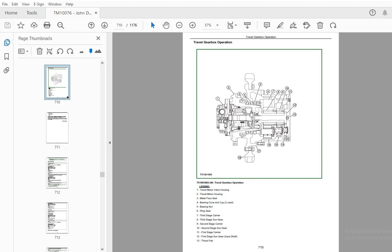
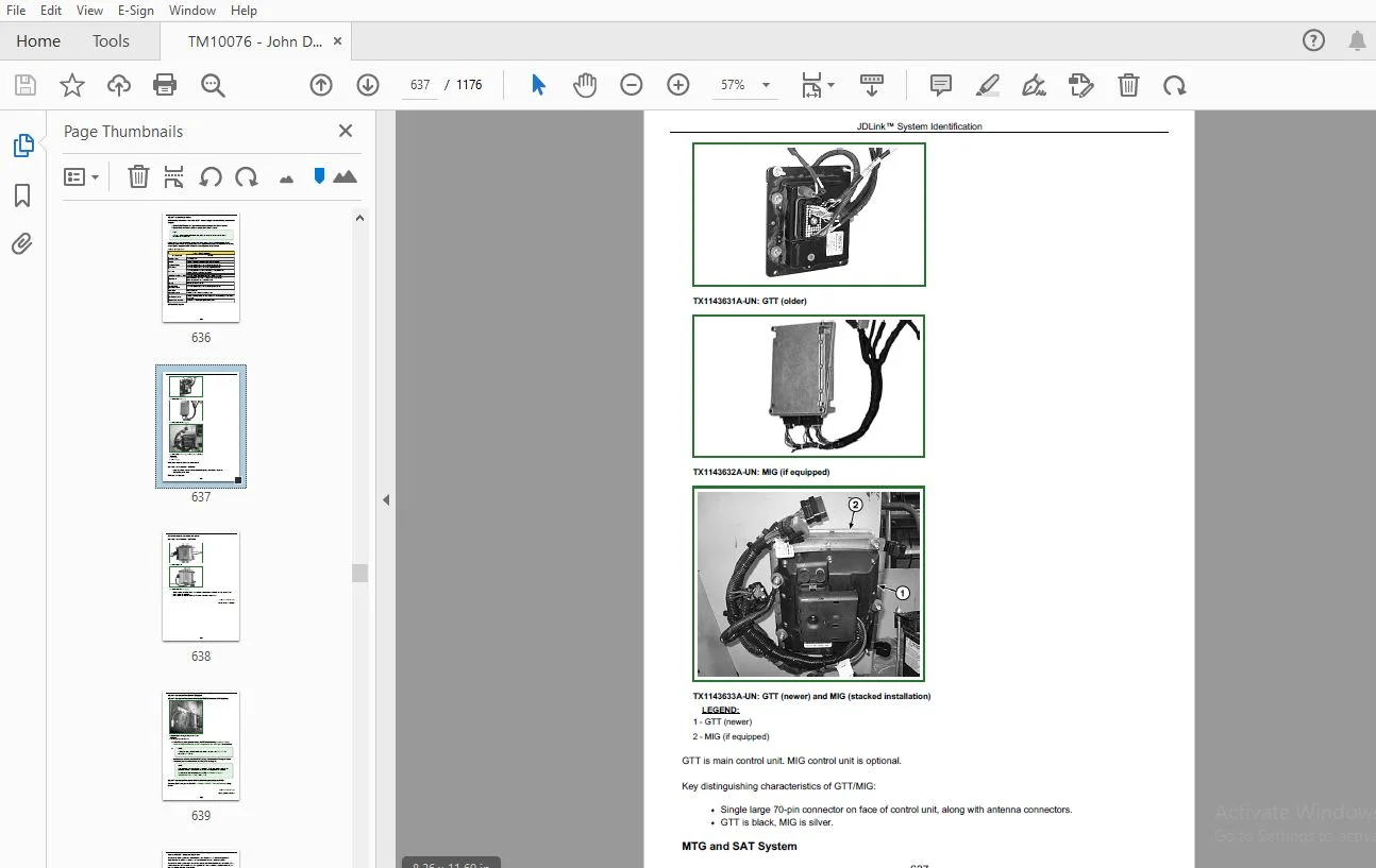
TABLE OF CONTENTS.....................................................................................   1
Section 9000: General Information.....................................................................  16
	Group 01: Safety..................................................................................  16
		Recognize Safety Information..................................................................  18
		Follow Safety Instructions....................................................................  19
		Operate Only If Qualified.....................................................................  20
		Wear Protective Equipment.....................................................................  21
		Avoid Unauthorized Machine Modifications......................................................  22
		Add Cab Guarding for Special Uses.............................................................  23
		Inspect Machine...............................................................................  24
		Stay Clear of Moving Parts....................................................................  25
		Avoid High-Pressure Fluids....................................................................  26
		Avoid High-Pressure Oils......................................................................  27
		Beware of Exhaust Fumes.......................................................................  28
		Prevent Fires.................................................................................  29
		Prevent Battery Explosions....................................................................  30
		Handle Chemical Products Safely...............................................................  31
		Dispose of Waste Properly.....................................................................  32
		Prepare for Emergencies.......................................................................  33
		Use Steps and Handholds Correctly.............................................................  34
		Start Only From Operator's Seat...............................................................  35
		Use and Maintain Seat Belt....................................................................  36
		Prevent Unintended Machine Movement...........................................................  37
		Avoid Worksite Hazards........................................................................  38
		Keep Riders Off Machine.......................................................................  40
		Avoid Backover Accidents......................................................................  41
		Avoid Machine Tip Over........................................................................  42
		Use Special Care When Lifting Objects.........................................................  44
		Add and Operate Attachments Safely............................................................  45
		Park and Prepare for Service Safely...........................................................  46
		Service Cooling System Safely.................................................................  47
		Remove Paint Before Welding or Heating........................................................  48
		Make Welding Repairs Safely...................................................................  49
		Drive Metal Pins Safely.......................................................................  50
Section 9001: Diagnostics.............................................................................  51
	Group 10: Main Controller (MCF) Diagnostic Trouble Codes..........................................  56
		Main Controller (MCF) Diagnostic Trouble Codes................................................  56
		11000.02 - Abnormal EEPROM....................................................................  51
		11001.02 - Abnormal RAM.......................................................................  51
		11002.02 - Abnormal A/D Conversion............................................................  51
		11003.03 - Abnormal Sensor Voltage............................................................  51
		11004.02 - Abnormal CAN Communication.........................................................  51
		11100.02 - Abnormal Engine Speed..............................................................  51
		11101.03 - Engine Control Dial Voltage High...................................................  51
		11101.04 - Engine Control Dial Sensor Voltage Low.............................................  51
		11200.03 - Pump 1 Delivery Pressure Sensor Voltage High.......................................  51
		11200.04 - Pump 1 Delivery Pressure Sensor Voltage Low........................................  51
		11202.03 - Pump 2 Delivery Pressure Sensor Voltage High.......................................  51
		11202.04 - Pump 2 Delivery Pressure Sensor Voltage Low........................................  51
		11206.03 - Pump 1 Control Pressure Sensor Voltage High........................................  51
		11206.04 - Pump 1 Control Pressure Sensor Voltage Low.........................................  51
		11208.03 - Pump 2 Control Pressure Sensor Voltage High........................................  51
		11208.04 - Pump 2 Control Pressure Sensor Voltage Low.........................................  51
		11301.03 - Swing Pilot Pressure Sensor Voltage High...........................................  51
		11301.04 - Swing Pilot Pressure Sensor Voltage Low............................................  51
		11302.03 - Boom Up Pilot Pressure Sensor Voltage High.........................................  51
		11302.04 - Boom Up Pilot Pressure Sensor Voltage Low..........................................  51
		11303.03 - Arm In Pilot Pressure Sensor Voltage High..........................................  51
		11303.04 - Arm In Pilot Pressure Sensor Voltage Low...........................................  51
		11304.03 - Travel Pilot Pressure Sensor Voltage High..........................................  51
		11304.04 - Travel Pilot Pressure Sensor Voltage Low...........................................  51
		11307.03 - Front Attachment Pilot Pressure Sensor Voltage High................................  51
		11307.04 - Front Attachment Pilot Pressure Sensor Voltage Low.................................  51
		11400.02 - Pump 2 Flow Rate Limit Solenoid Current Feedback Abnormal..........................  51
		11400.03 - Pump 2 Flow Rate Limit Solenoid Current Feedback Abnormal..........................  51
		11400.04 - Pump 2 Flow Rate Limit Solenoid Feedback Current Low...............................  51
		11401.02 - Torque Control Solenoid Feedback Current Abnormal..................................  51
		11401.03 - Torque Control Solenoid Feedback Current High......................................  52
		11401.04 - Torque Control Solenoid Feedback Current Low.......................................  52
		11402.02 - Dig Regenerative Solenoid Feedback Current Abnormal................................  52
		11402.03 - Dig Regenerative Solenoid Feedback Current High....................................  52
		11402.04 - Dig Regenerative Solenoid Feedback Current Low.....................................  52
		11403.02 - Arm Regenerative Solenoid Feedback Current Abnormal................................  52
		11403.03 - Arm Regenerative Solenoid Feedback Current High....................................  52
		11403.04 - Arm Regenerative Solenoid Feedback Current Low.....................................  52
		11404.02 - Power Dig Solenoid Feedback Current Abnormal.......................................  52
		11404.03 - Power Dig Solenoid Feedback Current High...........................................  52
		11404.04 - Power Dig Solenoid Feedback Current Low............................................  52
		11405.02 - Travel Speed Solenoid Feedback Current Abnormal....................................  52
		11405.03 - Travel Speed Solenoid Feedback Current High........................................  52
		11405.04 - Travel Speed Solenoid Feedback Current Low.........................................  52
		11901.03 - Hydraulic Oil Temperature Sensor Voltage High......................................  52
		11901.04 - Hydraulic Oil Temperature Sensor Voltage Low.......................................  52
		11910.02 - Actual Engine Speed Message Error..................................................  52
		11911.02 - Security Signal Received from Monitor..............................................  52
		11914.02 - Radiator Coolant Temperature Message Error.........................................  52
		11918.02 - Work Mode Received Message Error...................................................  52
		11920.02 - Fuel Flow Rate Message Error.......................................................  52
		20100.02 - Engine Coolant Overheat Message....................................................  52
	Group 20: Engine Control Unit (ECU) Diagnostic Trouble Codes...................................... 220
		Engine Control Unit (ECU) Diagnostic Trouble Codes............................................ 220
		171.03 - Intake Air Temperature Sensor Out of Range High......................................  52
		171.04 - Intake Air Temperature Sensor Out of Range Low.......................................  52
		647.05 - Proportional Fan Speed Solenoid Driver Open..........................................  52
		647.31 - Fan Manual Reverse Mode Input Active Too Long........................................  52
		898.09 - Engine Speed Request Not Received or Timed Out.......................................  52
		1638.09 - Hydraulic Oil Temperature Message Not Received or Timed Out.........................  52
	Group 30: Information Controller (ICF) Diagnostic Trouble Codes................................... 259
		Information Controller (ICF) Diagnostic Trouble Codes......................................... 259
		14000.02 - Abnormal CAN Communication.........................................................  52
		14001.02 - ICF: Flash Memory: Read/Write Error................................................  53
		14002.02 - ICF: External RAM: Read/Write Error................................................  53
		14003.02 - ICF: EEPROM: Sum Check Error.......................................................  53
		14006.02 - ICF: Satellite Communication Terminal: Communication Error.........................  53
		14008.02 - ICF: Abnormal Internal RAM.........................................................  53
		14100.02 - Satellite Communication Terminal: Abnormal EEPROM..................................  53
		14101.02 - Satellite Communication Terminal: Abnormal IB/OB Queue.............................  53
		14102.02 - Satellite Communication Terminal: Abnormal Local Loop Back.........................  53
		14103.02 - Satellite Communication Terminal: The Satellite is not found.......................  53
		14104.02 - Satellite Communication Terminal: Fail 1 of Remote Loop Back.......................  53
		14105.02 - Satellite Communication Terminal: Tail 2 of Remote Loop Back.......................  53
		14106.02 - Satellite Communication Terminal: Sending and Receiving Data are Mismatched........  53
	Group 40: Air Conditioner Controller (ACF) Diagnostic Trouble Codes............................... 292
		Air Conditioner Controller (ACF) Diagnostic Trouble Codes..................................... 292
		21 - Mix Door Open Circuit....................................................................  53
Section 9005: Operational Checkout Procedure.......................................................... 326
	Group 10: Operational Checkout Procedure.......................................................... 326
		Operational Checkout.......................................................................... 374
Section 9010: Engine.................................................................................. 421
	Group 05: Theory of Operation..................................................................... 421
		Engine Fuel System Component Location......................................................... 424
		Engine Cooling System Component Location...................................................... 426
		Cold Weather Starting Aid..................................................................... 428
		Engine Speed Control System Operation......................................................... 429
	Group 15: Diagnostic Information.................................................................. 421
		PowerTech Plus™ 4.5 L and 6.8 L (4045 and 6068) John Deere Engines............................ 434
	Group 25: Tests................................................................................... 421
		Radiator Temperature Differential Check....................................................... 438
		Engine Power Test Using Turbocharger Boost Pressure........................................... 441
Section 9015: Electrical System....................................................................... 444
	Group 05: System Information...................................................................... 444
		Electrical Diagram Information................................................................ 456
	Group 10: System Diagrams......................................................................... 444
		Explanation of Wire Markings.................................................................. 465
		Fuse and Relay Specifications................................................................. 466
		System Functional Schematic, Component Location, and Wiring Diagram Master Legend............. 470
		System Functional Schematic................................................................... 477
		Cab Harness (W1) Component Location........................................................... 487
		Cab Harness (W1) Wiring Diagram............................................................... 489
		Machine Harness (W2) Component Location....................................................... 494
		Machine Harness (W2) Wiring Diagram........................................................... 499
		Monitor Harness (W3) Component Location....................................................... 505
		Monitor Harness (W3) Wiring Diagram........................................................... 506
		Engine Harness (W4) Component Location........................................................ 508
		Engine Harness (W4) Wiring Diagram............................................................ 515
		Engine Interface Harness (W5) Component Location.............................................. 519
		Engine Interface Harness (W5) Wiring Diagram.................................................. 521
		Right Console Harness (W7) Component Location................................................. 524
		Right Console Harness (W7) Wiring Diagram..................................................... 527
		Pump Harness (W8) Component Location.......................................................... 529
		Pump Harness (W8) Wiring Diagram.............................................................. 530
		Auxiliary Fuse Box Harness (W9) Component Location............................................ 531
		Auxiliary Fuse Box Harness (W9) Wiring Diagram................................................ 533
		Pilot Shutoff Switch Harness (W11) Component Location......................................... 535
		Pilot Shutoff Switch Harness (W11) Wiring Diagram............................................. 536
		Air Suspension Seat Harness (W12) Component Location.......................................... 537
		Air Suspension Seat Harness (W12) Wiring Diagram.............................................. 539
		Seat Heater Switch Harness (W13) Component Location........................................... 540
		Seat Heater Switch Harness (W13) Wiring Diagram............................................... 541
		Multi-Function Pilot Control Lever Harness (W14) Component Location........................... 542
		Multi-Function Pilot Control Lever Harness (W14) Wiring Diagram............................... 544
		Travel Alarm Cancel Switch Harness (W15) Component Location................................... 545
		Travel Alarm Cancel Switch Harness (W15) Wiring Diagram....................................... 546
		Fan Reversing Switch Harness (W16) Component Location......................................... 547
		Fan Reversing Switch Harness (W16) Wiring Diagram............................................. 548
		Pilot Shutoff Valve Harness (W17) Component Location.......................................... 549
		Pilot Shutoff Valve Harness (W17) Wiring Diagram.............................................. 550
		Attachment Harness (W20) Component Location................................................... 551
		Attachment Harness (W20) Wiring Diagram....................................................... 552
		2-Speed Harness (W21) Component Location...................................................... 445
		2-Speed Harness (W21) Wiring Diagram.......................................................... 445
		Alternator Harness (W22) Component Location................................................... 555
		Alternator Harness (W22) Wiring Diagram....................................................... 556
		Start Aid Switch Harness (W23) Component Location............................................. 557
		Start Aid Switch Harness (W23) Wiring Diagram................................................. 558
		Starter Harness (W27) Component Location...................................................... 559
		Starter Harness (W27) Wiring Diagram.......................................................... 561
		Auxiliary Solenoid Harness (W61) Component Location........................................... 563
		Auxiliary Solenoid Harness (W61) Wiring Diagram............................................... 565
		JDLink™ System Harnesses Component Location—MIG/GTT........................................... 567
		JDLink™ System Harnesses Component Location—MTG/SAT........................................... 569
		JDLink™ System Wiring Diagrams—MIG/GTT........................................................ 571
		JDLink™ System Wiring Diagrams—MTG/SAT........................................................ 576
	Group 15: Sub-System Diagnostics.................................................................. 445
		Controller Area Network (CAN) Theory of Operation............................................. 580
		Starting and Charging Circuit Theory of Operation............................................. 583
		Monitor Controller Circuit Theory of Operation................................................ 588
		Engine Control Unit (ECU) Circuit Theory of Operation......................................... 592
		Main Controller (MCF) Circuit Theory of Operation............................................. 596
		Information Controller (ICF) Circuit Theory of Operation...................................... 602
		Travel Alarm Circuit Theory of Operation...................................................... 604
		Windshield Wiper and Washer Circuit Theory of Operation....................................... 606
		Pilot Shutoff Circuit Theory of Operation..................................................... 608
		Attachment Control Circuit Theory of Operation................................................ 610
		JDLink™ Circuit Theory of Operation—If Equipped............................................... 617
	Group 16: Monitor Operation....................................................................... 446
		Monitor Menu Operation........................................................................ 621
		Monitor Service Menu Operation................................................................ 622
	Group 20: References.............................................................................. 446
		Monitor Data Items............................................................................ 630
		Reading Diagnostic Trouble Codes With Monitor Display......................................... 632
		JDLink™ System Identification................................................................. 636
		JDLink™ Connection Procedure—If Equipped...................................................... 639
		Service ADVISOR™ Diagnostic Application....................................................... 640
		Service ADVISOR™ Connection Procedure......................................................... 641
		Reading Diagnostic Trouble Codes With Service ADVISOR™ Diagnostic Application................. 642
		Fuse Test..................................................................................... 645
		Relay Test.................................................................................... 650
		Pressure Sensor Test.......................................................................... 651
		Solenoid Test................................................................................. 653
		Proportional Solenoid Test.................................................................... 654
		Temperature Sensor Test....................................................................... 655
		Alternator Test............................................................................... 656
		Electrical Component Checks................................................................... 658
		Battery Remove and Install.................................................................... 664
		Rear Cover Remove and Install................................................................. 667
		Main Controller (MCF) Remove and Install...................................................... 668
		Engine Control Unit (ECU) Remove and Install.................................................. 669
		Information Controller (ICF) Remove and Install............................................... 671
		Monitor Controller Remove and Install......................................................... 672
		Key Switch Remove and Install................................................................. 675
		Switch Panel Remove and Install............................................................... 677
		Travel Alarm Remove and Install............................................................... 679
		Left Console Switch Remove and Install........................................................ 680
		Disconnect Tab Retainer Connectors............................................................ 681
		Disconnecting Spring Wire Clip Connectors..................................................... 682
		Replace DEUTSCH DEUTSCH is a trademark of the Deutsch Co. Connectors.......................... 446
		Replace DEUTSCH DEUTSCH is a trademark of Deutsch Co. Rectangular or Triangular Connectors.... 446
		Install DEUTSCH DEUTSCH is a trademark of the Deutsch Co. Contact............................. 447
		Replace WEATHER PACK WEATHER PACK is a trademark of Packard Electric. Connector............... 447
		Install WEATHER PACK WEATHER PACK is a trademark of Packard Electric. Contact................. 447
		Replace (Pull Type) Metri-Pack™ Connectors.................................................... 693
		Replace (Push Type) Metri-Pack™ Connectors.................................................... 695
		Replace CINCH CINCH is a trademark of the Cinch Co. Connectors................................ 447
		Install CINCH CINCH is a trademark of the Cinch Co. Contact................................... 447
		Repair 32 and 48 Way CINCH CINCH is a trademark of the Cinch Co. Connectors................... 447
		Remove Connector Body from Blade Terminals.................................................... 704
Section 9020: Power Train............................................................................. 705
	Group 05: Theory of Operation..................................................................... 705
		Track Adjuster and Recoil Spring Operation.................................................... 708
		Travel Gearbox Operation...................................................................... 710
	Group 15: Diagnostic Information.................................................................. 705
		Diagnose Undercarriage Components Malfunctions................................................ 705
		Measure Swing Bearing Wear.................................................................... 726
Section 9025: Hydraulic System........................................................................ 730
	Group 05: Theory of Operation..................................................................... 730
		Hydraulic System Diagram and Operation........................................................ 736
		Fan Drive Hydraulic System Operation—If Equipped (Serial No. —511303)......................... 738
		Fan Drive Hydraulic System Operation—If Equipped (Serial No. 511304— )........................ 742
		Pilot System Diagram and Operation............................................................ 746
		Pilot Pump, Pressure Regulating Valve and Filter Operation.................................... 749
		Pilot Shutoff Solenoid Valve Operation........................................................ 751
		Pilot Control Valve Operation................................................................. 785
		Travel Pilot Control Valve Operation.......................................................... 785
		Pilot Operation of Control Valve Operation.................................................... 785
		Pilot Signal Manifold Operation............................................................... 762
		Pump 1, Pump 2 and Drive Gearbox Operation.................................................... 772
		Pump 1 and Pump 2 Regulator Operation......................................................... 775
		Engine Speed Sensing Control Circuit Operation................................................ 783
		Control Valve Operation....................................................................... 785
		Control Valve Check Valves Identification and Operation....................................... 797
		Main Relief and Power Digging Valve Circuit Operation......................................... 801
		Circuit Relief and Anticavitation Valve Operation............................................. 806
		Travel Flow Combiner Valve Operation.......................................................... 808
		Boom Lower Meter-In Cut Valve Operation....................................................... 811
		Boom Regenerative Valve Circuit Operation..................................................... 814
		Dig Regenerative Valve Circuit Operation...................................................... 817
		Arm Regenerative Valve Circuit Operation...................................................... 821
		Bucket Regenerative Valve Circuit Operation................................................... 826
		Boom and Arm Reduced Leakage Valves Operation................................................. 829
		Arm 1 Flow Rate Control Valve Circuit Operation............................................... 831
		Arm 2 Flow Rate Control Valve Circuit Operation............................................... 835
		Bucket Flow Rate Control Valve Circuit Operation.............................................. 839
		Boom Flow Rate Control Valve Circuit Operation................................................ 843
		Auxiliary Flow Rate Control Valve Circuit Operation........................................... 847
		Swing Reduction Gearbox Operation............................................................. 852
		Swing Motor, Crossover Relief Valve, and Make-Up Check Valve Operation........................ 853
		Swing Motor Dampener Valve Operation.......................................................... 857
		Swing Motor Park Brake Release Circuit Operation.............................................. 869
		Center Joint Operation........................................................................ 870
		Travel Motor and Park Brake Valve Operation................................................... 871
		Travel Motor Speed Circuit Operation.......................................................... 879
		Cylinder Operation............................................................................ 882
		Return Filter Operation....................................................................... 884
		Auxiliary System Operation.................................................................... 885
		Auxiliary Pilot Control Valve Operation....................................................... 886
		Flow Rate Select Solenoid Valve Operation..................................................... 893
		Flow Rate Pressure Reducing Valve Operation................................................... 895
		Secondary Auxiliary Relief Valve Solenoid Valve Operation..................................... 897
		Secondary Auxiliary Relief Control Valve Operation............................................ 898
		Secondary Auxiliary Relief Valve Operation.................................................... 899
		Selector Valve Solenoid Valve Operation....................................................... 900
		Selector Valve Operation...................................................................... 901
		Auxiliary Flow Combiner Valve Operation....................................................... 903
		Auxiliary Shuttle Valve Operation............................................................. 906
		Auxiliary High Flow Line Kit Operation........................................................ 908
		Two Way Solenoid Kit Operation................................................................ 912
		Two Pump Combined Flow Kit Operation.......................................................... 916
		Secondary Auxiliary Relief Kit Operation...................................................... 922
		Low Flow Kit Operation........................................................................ 926
	Group 15: Diagnostic Information.................................................................. 731
		All Hydraulic Functions Slow.................................................................. 731
		Hydraulic Oil Overheats....................................................................... 731
		No Hydraulic Functions........................................................................ 731
		No Hydraulic Functions—Electrical Checks...................................................... 731
		Function Does Not Stop When Control Lever Released............................................ 731
		Load Drifts Down When Control Lever is in Neutral Position.................................... 731
		Load Falls When Control Valve is Actuated To Raise Load....................................... 731
		H/P (High Power) Function Does Not Operate, PWR (Power) Mode is Normal........................ 731
		Boom Down Does Not Function, Moves Slowly, or is Erratic, All Other Functions Normal.......... 731
		Arm In Does Not Function, Moves Slowly, or is Erratic, All Other Functions Normal............. 732
		Swing Speed Slow During Arm In Function....................................................... 732
		Boom Cannot Raise Track Off Ground............................................................ 732
		Swing Function Does Not Operate in Both Directions............................................ 732
		Swing Speed Slow in Both Directions........................................................... 732
		Swing Speed Slow or Does Not Operate in One Direction......................................... 732
		Upperstructure Drift With Swing Valve in Neutral.............................................. 732
		Machine Freewheels Down an Incline............................................................ 732
		Track Will Not Move in Either Direction....................................................... 732
		Machine Mistracks............................................................................. 732
		Machine Mistracks Left During Combined Travel and Dig Functions............................... 732
		Machine Will Not Shift Into Fast (Rabbit) Speed............................................... 732
		Pump 1, Pump 2, and Pilot Pump Line Identification............................................ 991
		Control Valve Line Identification............................................................. 993
		Swing Motor Line Identification............................................................... 997
		Pilot Control Valve-to-Pilot Signal Manifold Component Location—Excavator Pattern............. 998
		Pilot Control Valve-to-Pilot Signal Manifold Component Location—Backhoe Pattern...............1000
		Pilot Signal Manifold-to-Control Valve Line Connection........................................1002
		Travel System Component Location..............................................................1005
		Travel Hydraulic System Line Connection.......................................................1007
		Auxiliary Attachment Schematic................................................................1009
		Auxiliary System Line Connections.............................................................1018
		Hydraulic System Schematic....................................................................1020
		Hydraulic System Component Location...........................................................1029
		Hydraulic System Line Connections.............................................................1030
		Fan Drive Hydraulic System Component Location.................................................1031
		Fan Drive Hydraulic System Schematic (S.N. 511304— )..........................................1032
		Fan Drive Hydraulic System Schematic (S.N. —511303)...........................................1035
	Group 25: Tests................................................................................... 732
		JT05800 Digital Thermometer Installation......................................................1039
		JT02156A Digital Pressure/Temperature Analyzer Installation...................................1040
		Hydraulic Oil Cleanup Procedure With Portable Filter Caddy....................................1041
		Hydraulic Oil Warm-Up Procedure...............................................................1042
		Pilot Pressure Regulating Valve Test and Adjustment...........................................1045
		Control Valve Spool Actuating Pilot Pressure Test.............................................1049
		Dig Regenerative Solenoid Valve Test and Adjustment...........................................1052
		Arm Regenerative Solenoid Valve Test and Adjustment...........................................1056
		Power Digging Solenoid Valve Test and Adjustment..............................................1060
		Travel Speed Solenoid Valve Test and Adjustment...............................................1064
		Pump Control Pilot Pressure Signal Test.......................................................1069
		Torque Control Solenoid Valve Test and Adjustment.............................................1072
		Main Relief and Power Digging Valve Test and Adjustment.......................................1076
		Circuit Relief Valve Test and Adjustment......................................................1082
		Swing Motor Crossover Relief Valve Test and Adjustment........................................1088
		Travel Motor Crossover Relief Valve Test and Adjustment.......................................1093
		Pump Regulator Test and Adjustment—Minimum Flow...............................................1098
		Pump Regulator Test and Adjustment—Maximum Flow...............................................1102
		Pump Flow Test................................................................................1105
		Swing Motor Leakage Test......................................................................1115
		Travel Motor Leakage Test.....................................................................1118
		Cylinder Drift Test—Boom, Arm, and Bucket.....................................................1122
		Fan Drive Pump Flow Test......................................................................1124
		Fan Speed Test................................................................................1128
Section 9031: Heating and Air Conditioning............................................................1131
	Group 05: Theory of Operation.....................................................................1131
		Air Conditioning System Cycle of Operation....................................................1134
	Group 15: Diagnostic Information..................................................................1131
		Diagnose Air Conditioning System Malfunctions.................................................1139
		Diagnose Heating System Malfunctions..........................................................1142
		Heater and Air Conditioner Diagnostic Trouble Code Check......................................1144
		Heater and Air Conditioner Component Location.................................................1151
	Group 25: Tests...................................................................................1131
		Refrigerant Cautions and Proper Handling......................................................1153
		Heater and Air Conditioner Operational Checks.................................................1154
		R134a Air Conditioning System Test............................................................1158
		Air Conditioner Compressor Clutch Test........................................................1161
		Refrigerant Leak Test.........................................................................1162
		Refrigerant Hoses and Tubing Inspection.......................................................1163
		Air Conditioner Compressor Belt Check and Adjustment..........................................1164
		Operating Pressure Diagnostic Chart...........................................................1165
Section 9050: Reference Material......................................................................1167
	Group 05: Terminology Cross Reference Chart.......................................................1170
		Terminology Cross Reference Chart.............................................................1170
Section 9900: Dealer Fabricated Tools.................................................................1172
	Group 99: Dealer Fabricated Tools.................................................................1172
		DFT1218 Split Flange Hose Cap.................................................................1174
S.S 16/02/2025