John Deere 135D Excavator Operation and Test & TECHNICAL MANUAL TM10742 – PDF DOWNLOAD
$29.95
John Deere 135D Excavator Operation and Test & TECHNICAL MANUAL TM10742 – PDF DOWNLOAD
Description
John Deere 135D Excavator Operation and Test & TECHNICAL MANUAL TM10742 – PDF DOWNLOAD
FILE DETAILS:
John Deere 135D Excavator Operation and Test & TECHNICAL MANUAL TM10742 – PDF DOWNLOAD
Language : English
Pages :930
Downloadable : Yes
File Type : PDF
IMAGES PREVIEW OF THE MANUAL:
DESCRIPTION:
John Deere 135D Excavator Operation and Test & TECHNICAL MANUAL TM10742 – PDF DOWNLOAD
Foreword
- This manual is written for an experienced technician. Essential tools required in performing certain service work are identified in this manual and are recommended for use.
- Live with safety: Read the safety messages in the introduction of this manual and the cautions presented throughout the text of the manual. This is the safety-alert symbol. When you see this symbol on the machine or in this manual, be alert to the potential for personal injury. Technical manuals are divided in two parts: repair and operation and tests. Repair sections tell how to repair the components.
- Operation and tests sections help you identify the majority of routine failures quickly. Information is organized in groups for the various components requiring service instruction. At the beginning of each group are summary listings of all applicable essential tools, service equipment and tools, other materials needed to do the job, service parts kits,
- specifications, wear tolerances, and torque values. Technical Manuals are concise guides for specific machines. They are on-the-job guides containing only the vital information needed for diagnosis, analysis, testing, and repair. Fundamental service information is available from other sources covering basic theory of operation, fundamentals of troubleshooting, general maintenance, and basic type of failures and their causes.
TABLE OF CONTENTS:
John Deere 135D Excavator Operation and Test & TECHNICAL MANUAL TM10742 – PDF DOWNLOAD
Contents 5
General Information 9
Safety 11
Recognize Safety Information 11
Follow Safety Instructions 11
Operate Only If Qualified 11
Wear Protective Equipment 12
Avoid Unauthorized Machine Modifications 12
Add Cab Guarding for Special Uses 13
Inspect Machine 13
Stay Clear of Moving Parts 13
Avoid High-Pressure Fluids 14
Avoid High-Pressure Oils 14
Beware of Exhaust Fumes 15
Prevent Fires 15
Prevent Battery Explosions 15
Handle Chemical Products Safely 16
Dispose of Waste Properly 16
Prepare for Emergencies 16
Use Steps and Handholds Correctly 17
Start Only From Operator’s Seat 17
Use and Maintain Seat Belt 17
Prevent Unintended Machine Movement 18
Avoid Work Site Hazards 19
Keep Riders Off Machine 19
Avoid Backover Accidents 20
Avoid Machine Tip Over 20
Use Special Care When Lifting Objects 21
Add and Operate Attachments Safely 21
Prevent Unintended Detonation of Explosive Devices 21
Park and Prepare for Service Safely 22
Service Cooling System Safely 23
Remove Paint Before Welding or Heating 24
Make Welding Repairs Safely 25
Drive Metal Pins Safely 25
Diagnostics 27
Main Controller (MCF) Diagnostic Trouble Codes 31
Main Controller (MCF) Diagnostic Trouble Codes 31
1100002 — Abnormal EEPROM 31
Controller Hardware Diagnostics 31
1100102 — Abnormal RAM 32
Controller Hardware Diagnostics 32
1100202 — Abnormal A/D Conversion 33
Controller Hardware Diagnostics 33
1100303 — Abnormal Sensor Voltage 34
Harness diagnostics 34
1100402 — Abnormal CAN Communication 35
Controller Area Network (CAN) Diagnostics 35
Engine Control Module (ECM) Diagnostic Trouble Codes151
Engine Control Module (ECM) Diagnostic Trouble Codes151
10003 — Engine Oil Pressure Sensor Voltage Low (P0522)151
10004 — Engine Oil Pressure Sensor Voltage High (P0523)152
10203 — Boost Pressure Sensor Voltage Low (P0237)152
10204 — Boost Pressure Sensor Voltage High (P0238)153
10503 — Boost Temperature Sensor Voltage High (P1113)153
10504 — Boost Temperature Sensor Voltage Low (P1112)154
10803 — Barometric Pressure Sensor Voltage Low (P0107)154
10804 — Barometric Pressure Sensor Voltage High (P0108)155
11000 — Engine Coolant Temperature Above Normal—Most Severe (P1173)155
11003 — Engine Coolant Temperature Sensor Voltage High (P0118)156
11004 — Engine Coolant Temperature Sensor Voltage Low (P0117)156
15700 — Common Rail Pressure—First Stage (P088)157
15700 — Common Rail Pressure—Second Stage (P088)158
15702 — Common Rail Pressure High (P0089)159
15703 — Common Rail Pressure Sensor Voltage High (P0193) 159
15704 — Common Rail Pressure Sensor Voltage Low (P0192)160
17203 — Intake Air Temperature Sensor Voltage High (P0113)160
17204 — Intake Air Temperature Sensor Voltage Low (P0112)161
17403 — Fuel Temperature Sensor Voltage High (P0183)161
17404 — Fuel Temperature Sensor Voltage Low (P0182)162
19000 — Engine Overspeed (P0219)162
62802 — ROM Malfunction (P0601)163
63307 — Pressure Limiter Open (P1095)163
63602 — Camshaft Position Sensor (G-Sensor) Signal Missing (P0340)164
63602 — Camshaft Position Sensor (G-Sensor) Signal Mismatch (P0341)164
63607 — Camshaft Position Sensor (G-Sensor) out of Phase (P1345)165
63902 — CAN Communication Error (U2104)165
63903 — CAN Timeout (U2106)166
65103 — Open Circuit in Injection Nozzle #1 (P0201)166
65203 — Open Circuit in Injection Nozzle #2 (P0202)167
65303 — Open Circuit in Injection Nozzle #3 (P0203)167
65403 — Open Circuit in Injection Nozzle #4 (P0204) 168
72302 — Crankshaft Position Sensor Signal Missing (P0335)168
72302 — Crankshaft Sensor Mismatch (P0336)169
98703 — Check Engine Lamp Malfunction (P0650)169
107702 — CPU Monitoring IC Malfunction (P0606)170
107902 — 5 Volt Power Supply #1 Malfunction (P1631)170
108002 — 5 Volt Power Supply #2 Malfunction (P1632)171
123901 — No Pump Pressure—First Stage (P0087)171
124001 — No Pump Pressure Feed—Second Stage (P1093)172
134700 — SCV #1 Open Circuit or Short to Ground (P0090)173
138103 — High Voltage Fault of Fuel Differential Pressure Sensor173
138104 — Low Voltage Fault of Fuel Differential Pressure Sensor173
148502 — Engine Control Module Relay Malfunction (P1625)174
1000103 — EGR Position Sensor Malfunction (P0487)174
1000202 — EGR Valve Control Malfunction (P0488)175
1000302 — Injection Nozzle Common #1 Malfunction (P1261)175
1000402 — Injection Nozzle Common #2 Malfunction (P1262)176
1000501 — Charge Circuit Malfunction—Bank 1 (P0611)176
1000601 — Charge Circuit Malfunction—Bank 2 (P0612)177
1000702 — Abnormal CPU (P0606)177
1000802 — A/D Conversion Malfunction (P1630)178
1000902 — 5 Volt Power Supply #3 Malfunction (P1633)178
1001002 — 5 Volt Power Supply #4 Malfunction (P1634)179
1001102 — 5 Volt Power Supply #5 Malfunction (P1635)180
1001302 — EEPROM Malfunction (P0603)180
Information Controller (ICF) Diagnostic Trouble Codes181
Information Controller (ICF) Diagnostic Trouble Codes181
1400002 — Abnormal CAN Communication181
1400102 — ICF: Flash Memory: Read / Write Error181
1400202 — ICF: External RAM: Read / Write Error182
1400302 — ICF: EEPROM: Sum Check Error182
1400602 — ICF: Satellite Communication Terminal: Communication Error182
1400802 — ICF: Abnormal Internal RAM182
1410002 — Satellite Communication Terminal: Abnormal EEPROM183
1410102 — Satellite Communication Terminal: Abnormal IB / OB Queue183
1410202 — Satellite Communication Terminal: Abnormal Local Loop Back183
1410302 — Satellite Communication Terminal: The Satellite is not found183
1410402 — Satellite Communication Terminal: Fail 1 of Remote Loop Back184
1410502 — Satellite Communication Terminal: Tail 2 of Remote Loop Back184
1410602 — Satellite Communication Terminal: Sending and Receiving Data are Mismatched184
Air Conditioner Controller (ACF) Diagnostic Trouble Codes185
Air Conditioner Controller (ACF) Diagnostic Trouble Codes185
21 — Mix Door Open Circuit185
Harness Diagnostics185
Engine233
Theory of Operation235
Engine Component Location235
Engine Fuel System Operation238
Cooling System Operation244
Engine Lubrication System Operation247
Engine Intake and Exhaust System Operation248
Engine Turbocharger Operation249
Exhaust Gas Recirculation (EGR) Operation250
Quick On System Operation252
Engine Speed Control System Operation253
Diagnostic Information259
4JJ1 Isuzu Diesel Engine259
Diagnose Engine Malfunctions259
Engine Cranks But Will Not Start259
Engine Cranks But Will Not Start Diagnostic Procedure260
Turbocharger Excessively Noisy or Vibrates282
Turbocharger Excessively Noisy or Vibrates Diagnostics Procedure282
Oil Dripping From Turbocharger Adapter282
Oil Dripping From Turbocharger Adapter Diagnostics Procedure283
Excessive Drag in Turbocharger Rotating Members283
Excessive Drag in Turbocharger Rotating Members Diagnostics Procedure283
Serpentine Belt Check and Adjust285
Fuel Supply Pressure Test286
Engine Valve Lash (Clearance) Check and Adjust287
Engine Compression Pressure Test289
Air Filter Restriction Indicator Switch Test291
Engine Power Test Using Turbocharger Boost Pressure293
Engine Oil Pressure Test296
Electrical System297
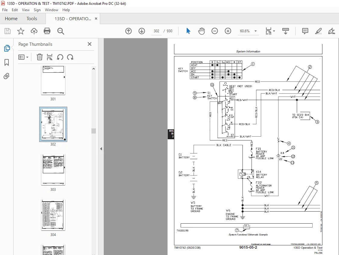
System Information301
Electrical Diagram Information301
System Diagrams311
Explanation of Wire Markings311
Fuse and Relay Specifications312
System Functional Schematic, Component Location, and Wiring Diagram Master Legend317
System Functional Schematic326
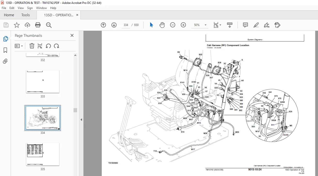
Cab Harness (W1) Component Location334
Cab Harness (W1) Wiring Diagram336
Machine Harness (W2) Component Location342
Machine Harness (W2) Wiring Diagram344
Monitor Harness (W3) Component Location350
Monitor Harness (W3) Wiring Diagram352
Engine Harness (W4) Component Location354
Engine Harness (W4) Wiring Diagram356
Heater and Air Conditioner Harness (W6) Component Location358
Heater and Air Conditioner Harness (W6) Wiring Diagram360
Right Console Harness (W7) Component Location362
Right Console Harness (W7) Wiring Diagram364
Pump Harness (W8) Component Location366
Pump Harness (W8) Wiring Diagram368
Auxiliary Fuse Box Harness (W9) Component Location370
Auxiliary Fuse Box Harness (W9) Wiring Diagram372
Travel Alarm Cancel Switch Sub Harness (W10) Component Location373
Travel Alarm Cancel Switch Sub Harness (W10) Wiring Diagram374
Pilot Shutoff Switch Harness (W11) Component Location375
Pilot Shutoff Switch Harness (W11) Wiring Diagram376
Air Suspension Seat Harness (W12) Component Location378
Air Suspension Seat Harness (W12) Wiring Diagram380
Seat Heater Switch Harness (W13) Component Location381
Seat Heater Switch Harness (W13) Wiring Diagram382
Multi-Function Pilot Control Lever Harness (W14) Component Location384
Multi-Function Pilot Control Lever Harness (W14) Wiring Diagram386
Travel Alarm Cancel Switch Harness (W15) Component Location387
Travel Alarm Cancel Switch Harness (W15) Wiring Diagram388
Pilot Shutoff Valve Harness (W17) Component Location389
Pilot Shutoff Valve Harness (W17) Wiring Diagram390
Lighter Harness (W19) Component Location391
Lighter Harness (W19) Wiring Diagram392
Attachment Harness (W20) Component Location394
Attachment Harness (W20) Wiring Diagram396
2-Speed Harness (W21) Component Location398
2-Speed Harness (W21) Wiring Diagram400
Service Advisor Connector Harness (W22) Component Location402
Service Advisor Connector Harness (W22) Wiring Diagram404
12-Volt Power Converter Harness (W23) Component Location405
12-Volt Power Converter Harness (W23) Wiring Diagram406
Sub-System Diagnostics409
Controller Area Network (CAN) Theory of Operation409
Starting and Charging Circuit Theory of Operation410
Monitor Controller Circuit Theory of Operation413
Engine Control Module (ECM) Circuit Theory of Operation418
Main Controller (MCF) Circuit Theory of Operation423
Information Controller (ICF) Circuit Theory of Operation428
Travel Alarm Circuit Theory of Operation430
Windshield Wiper and Washer Circuit Theory of Operation432
Pilot Shutoff Circuit Theory of Operation434
Attachment Control Circuit Theory of Operation436
Monitor Operation443
Monitor Menu Operation443
Monitor Service Menu Operation443
References447
Monitor Data Items447
Reading Diagnostic Trouble Codes With Monitor Display449
Service ADVISOR™ Diagnostic Application452
Service ADVISOR™ Connection Procedure453
Reading Diagnostic Trouble Codes With Service ADVISOR™ Diagnostic Application454
Dr ZX Diagnostic Application457
Personal Digital Assistant (PDA) Connection to Excavator Using Dr ZX Application457
Reading Diagnostic Trouble Codes With Dr ZX461
Main Controller (MCF) Monitor Display Using Dr ZX463
Main Controller (MCF) Special Function Using Dr ZX471
Main Controller (MCF) Setup Using Dr ZX475
Engine Control Module (ECM) Monitor Display Using Dr ZX488
Engine Control Module (ECM) Special Function Using Dr ZX495
Monitor Controller Monitoring Using Dr ZX520
Monitor Controller Various Setup Using Dr ZX523
Dr ZX Password Change527
Machine Information Center (MIC) Application530
Information Controller (ICF) Initialization530
Information Controller (ICF) Model and Serial Number534
Information Controller (ICF) Date and Time538
Information Controller (ICF) Control Data: Initialize542
Information Controller (ICF) Satellite Terminal545
Information Controller (ICF) Data Download546
Information Controller (ICF) Recorded Data550
Fuse Test553
Relay Test557
Pressure Sensor Test558
Solenoid Test559
Proportional Solenoid Test559
Temperature Sensor Test560
Alternator Test561
Electrical Component Checks563
Component Checks563
Battery Remove and Install566
Rear Cover Remove and Install567
Main Controller (MCF) Remove and Install569
Engine Control Module (ECM) Remove and Install570
Information Controller (ICF) Remove and Install572
Monitor Controller Remove and Install575
Key Switch Remove and Install577
Switch Panel Remove and Install578
Travel Alarm Remove and Install579
Left Console Switch Remove and Install580
Disconnect Tab Retainer Connectors580
Disconnecting Spring Wire Clip Connectors581
Replace DEUTSCH™ Connectors581
Replace DEUTSCH™ Rectangular or Triangular Connectors582
Install DEUTSCH™ Contact583
Replace WEATHER PACK™Connector584
Install WEATHER PACK™Contact585
Replace (Pull Type) Metri-Pack™ Connectors587
Replace (Push Type) Metri-Pack™ Connectors588
Replace CINCH™ Connectors589
Install CINCH™ Contact591
Repair 32 and 48 Way CINCH™ Connectors592
Remove Connector Body from Blade Terminals595
Power Train597
Theory of Operation599
Track Adjuster and Recoil Spring Operation599
Travel Gearbox Operation600
Diagnostic Information601
Diagnose Undercarriage Components Malfunctions601
Noisy or Loose Track Chain601
Measure Swing Bearing Wear605
Hydraulic System609
Theory of Operation611
Hydraulic System Operation611
Pilot System Operation613
Pilot Pump, Pressure Regulating Valve and Filter Operation615
Pilot Shutoff Solenoid Valve Operation616
Pilot Control Valve Operation619
Travel Pilot Control Valve Operation622
Pilot Operation of Control Valve Operation626
Pilot Signal Manifold Operation631
Pump 1, Pump 2 and Drive Gearbox Operation644
Pump 1 and Pump 2 Regulator Operation648
Engine Speed Sensing Control Circuit Operation656
Control Valve Operation657
Control Valve Check Valves Identification and Operation678
Main Relief Valve Circuit Operation682
Circuit Relief and Anticavitation Valve Operation684
Flow Combiner Valve Operation686
Auxiliary Flow Combiner Valve and Bypass Shut-Off Valve Operation688
Boom Regenerative Valve Circuit Operation691
Arm Regenerative Valve Circuit Operation692
Bucket Regenerative Valve Circuit Operation696
Boom and Arm Reduced Leakage Valves Operation698
Bucket Flow Rate Control Valve Circuit Operation700
Auxiliary Flow Rate Control Valve Circuit Operation703
Blade Circuit Operation—If Equipped704
Swing Reduction Gearbox Operation708
Swing Motor, Crossover Relief Valve, and Make-Up Check Valve Operation709
Swing Motor Park Brake Release Circuit Operation713
Center Joint Operation714
Travel Motor and Park Brake Valve Operation716
Travel Motor Speed Circuit Operation726
Cylinder Operation730
Return Filter Operation731
Diagnostic Information733
Diagnose Hydraulic System Malfunctions733
All Hydraulic Functions Slow733
Machine Will Not Hold Back And Park Brakes Engage And Disengage When Traveling Down An Incline766
767
Machine Will Not Turn Smoothly In One Direction Or Park Brake Grabs767
767
Pump 1, Pump 2, and Pilot Pump Line Identification768
Control Valve Line Identification770
Swing Motor Line Identification774
Pilot Control Valve-to-Pilot Signal Manifold Component Location—Excavator Pattern776
Pilot Control Valve-to-Pilot Signal Manifold Component Location—Backhoe Pattern778
Pilot Signal Manifold-to-Control Valve Line Connection779
Travel System Component Location781
Travel Hydraulic System Line Connection782
Blade Hydraulic System Component Location784
Hydraulic System Schematic786
Hydraulic System Component Location798
Hydraulic System Line Connections800
Tests803
JT05800 Digital Thermometer Installation803
JT02156A Digital Pressure/Temperature Analyzer803
General Oil Cleanup Procedure Using Portable Filter Caddy804
Hydraulic Component Failure Cleanup Procedure Using Portable Filter Caddy808
Hydraulic Oil Warm-Up Procedure814
Pilot Pressure Regulating Valve Test and Adjustment817
Control Valve Spool Actuating Pilot Pressure Test823
Arm Regenerative Solenoid Valve Test and Adjustment827
Travel Speed Solenoid Valve Test and Adjustment832
Torque Control Solenoid Valve Test and Adjustment837
Pump Control Pilot Pressure Signal Test842
Main Relief Valve Test and Adjustment845
Circuit Relief Valve Test and Adjustment848
Blade Main Relief Valve Test and Adjustment853
Swing Motor Crossover Relief Valve Test and Adjustment856
Travel Motor Crossover Relief Valve Test and Adjustment859
Pump Regulator Test and Adjustment—Minimum Flow863
Pump Regulator Test and Adjustment—Maximum Flow866
Pump Flow Test869
Swing Motor Leakage Test877
Travel Motor Leakage Test880
Cylinder Drift Test—Boom, Arm, and Bucket883
Heating and Air Conditioning885
Theory of Operation887
Air Conditioning System Cycle of Operation887
Diagnostic Information889
Diagnose Air Conditioning System Malfunctions889
Diagnose Heating System Malfunctions893
Heater and Air Conditioner Diagnostic Trouble Code Check895
Heater and Air Conditioner Component Location902
Tests905
Refrigerant Cautions and Proper Handling905
Heater and Air Conditioner Operational Checks906
Visual Inspection of Components906
Air Conditioner Compressor Clutch Test908
Refrigerant Leak Test909
Refrigerant Hoses and Tubing Inspection909
Air Conditioner Compressor Belt Check and Adjustment909
Operating Pressure Diagnostic Chart910
Reference Material911
Terminology Cross Reference Chart913
Terminology Cross Reference Chart913
Dealer Fabricated Tools915
Dealer Fabricated Tools917
DFT1218 Split Flange Hose Cap917
Page Numbers 5
Section 9000 9
Group 01 11
S.M 6/1/25