JCB Generator Control Panels Service Repair Manual – PDF Download
Original price was: $78.00.$28.95Current price is: $28.95.
JCB Generator Control Panels Service Repair Manual
Description
JCB Generator Control Panels Service Repair Manual
Description:
JCB Generator Control Panels Service Repair Manual
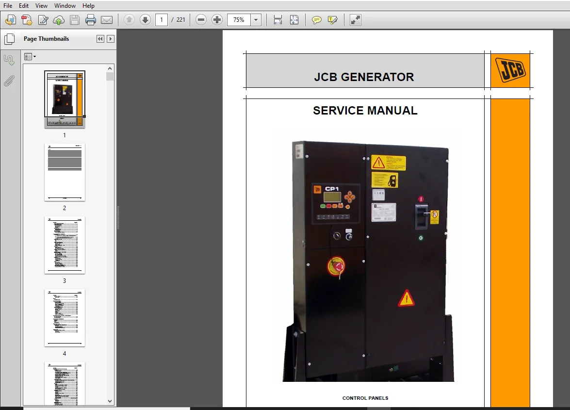
Control and protection controller is presented in a panel box of 72x72x75mm. It is manufactured according to DIN Title 43700 in NORYL UL 94 V-0 Self-extinguishing black colour. Offers the possibility to start the engine in MANUAL or AUTOMATIC mode (by means of a free-voltage contact) and protect it against possible breakdowns. The management is made through an electronic circuit based on a microcontroller and located inside the controller. In the front part we can find the ON/OFF switch, a RESET button, a key for selecting MANUAL; STOP or AUTOMATIC mode and 14 leds. In the back side we can find 18 switchable connection terminals divided in two blocks, 6 programming micro-switches and one port RJ11 for programming and searching the alarm recordings and hour-counter
Table of Contents:
JCB Generator Control Panels Service Repair Manual
Description and Main Features 1
Front Panel Components 2
Backside Components 5
Connection Terminals 5
Micro-switches 6
Port RJ11 7
Operation Modes 8
Recommendations 8
Operation Modes 8
Connection Diagram 9
Technical Features 10
Most Outstanding Advantages 11
CP1 and CP2 Digital Control Panels
Introduction 12
The Panel provides the following readings of the Electric Mains supply:
12
The panel provides the following Engine features information: 12
The panel controls the following functions of the engine: 12
Password 13
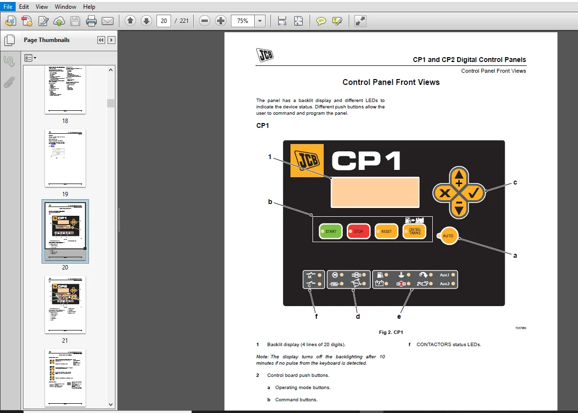
Control Panel Front Views 14
CP1 14
CP2 15
Control Panel Push Buttons 16
Operating Mode Buttons 16
Command buttons 16
Display Buttons 17
Contactors Buttons (CP2 only) 17
Data LED’s 18
Engine Status LED’s 18
Alarm LED’s 18
Electric Power Status LED’s 19
Starting and Stopping – Manual Mode 20
Starting 20
Stopping 20
Starting and Stopping – Automatic Mode 21
Operational Modes 22
Test Mode (CP2 only) 22
Block Mode (CP1 only) 22
Block Mode (CP2 only) 22
Activation of Contactors (CP2 only) 23
Linking Generators and Transfer Panels 23
Maintenance 24
Working Counters 24
Maintenance Counters 24
Fault History 25
Equipment List 25
Alarms 26
Engine Alarms 26
Generator Set Alarms 27
Mains Alarms (CP2 only) 27
Programmable Alarms and Inputs 28
Transfer Fuel Pump (Optional) 36
Gauging system for the fuel tank: 36
Inputs and Outputs 37
Digital Inputs 38
Annex I
Parameters Tables 43
Annex Il Device Display
Figures and Readings 55
Status of the Device 55
Generator Figures Displayed 55
Engine Status Display 55
Control Board Status Display 56
Power and Energy Display 57
Failures Record 58
Control Board Maintenance 59
Introducing Password 59
Inputs and Outputs 60
Counters 61
List of Failures 62
Events 62
Date/Hour 65
Language Selection 65
Control Board Programming 66
Annex lll Dimensions, Connections and Mechanisation
Measurements Module 68
Visualisation Module 76
Annex lV CAN Communications
Introduction 79
Topology 80
Wiring 81
Wiring Diagrams 83
Annex V Telesignal
Communication Option by Digital Outputs 86
Introduction 86
Telesignal Components 86
Telesignal Programming 88
Wiring of the Telesignal Option 89
Annex VI CCrs
Communication Option via Modem 96
Introduction 96
CCrs Installation 96
DSE Model 8610 and 8620 AMF Controller
Installation 98
Terminal Description 98
Analogue Sensors 101
Magnetic Pick-up, CAN and Expansion 102
V1 Load switching and Generator Voltage Sensing 104
V2 Mains Voltage Sensing (DSE8620 Only) 105
Generator Current Transformers 106
Mains Current Transformers (DSE 8620 Only) 107
Configurable Digital Inputs 108
PC Configuration Interface Connector 109
RS485 Connector 110
RS232 Connector 110
Description of Controls 111
DSE 8610 Automatic Mains Failure (AMF) Control Module below: 111
Viewing the Instrument Pages 115
Viewing The Event Log 124
User Configurable Indicators 125
Operation 126
Control 126
Control Push- Buttons (DSE 8610 Only) 127
Dummy Load/ Load Shedding Control 131
Stop Mode 132
Automatic Operation (DSE 8620 Only) 133
Manual Operation 137
Test Operation (DSE 8620 Only) 139
Protections 141
Protections Disabled 141
Indications 144
Warnings 145
High Current Warning Alarm 147
Shutdowns 148
Electrical Trips 150
High Current Shutdown / Electrical Trip Alarm 152
Earth Fault Shutdown / Electrical Trip Alarm 154
Short Circuit Alarm 155
Rocof/Vector Shift (DSE 8620 Only) 156
Scheduler 157
Stop Mode 157
Manual Mode 157
Auto Mode 157
Synchroscope Operation 158
Commissioning 159
Commissioning Screens 159
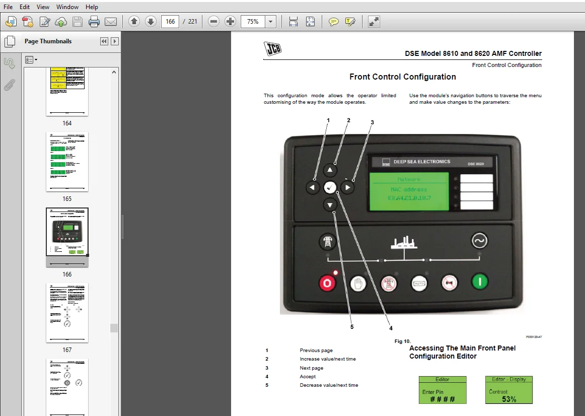
Front Control Configuration 160
Accessing The Main Front Panel Configuration Editor 160
Adjustable Parameters 163
Accessing The ‘running’ Configuration Editor 166
Fault Finding 169
DSE Model 8660 ATS and Mains Controller
Introduction 171
Specifications 172
Part Numbering 172
Installation 173
Terminal Description 173
Load Current T ransformer 180
Typical Arrangement of Dsenet® 185
Description of Controls 186
DSE8660 AMF Control Module 186
Quickstart Guide 187
Viewing the Instrument pages 190
Viewing the Event Log 193
User Configurable Indicators 194
Controls 196
Operation 198
Alternative Configurations 198
Stop Mode 198
Automatic mode 198
Manual Mode 200
Test Mode 201
Protections 202
Indications 202
Warnings 204
Electrical Trips 205
Scheduler 205
Front Panel Configuration 206
Accessing The Main Front Panel Configuration Editor 207
Accessing the ‘Running’ Configuration Editor 211
Commissioning 213
Pre-Commissioning 213
Fault Finding 214
Image Preview:
Questions? Email us: [email protected]
Please Note:
⦁ This is the SAME manual used by the dealers to troubleshoot any faults in your vehicle. This can be yours in 2 minutes after the payment is made.
⦁ Contact us at [email protected] should you have any queries before your purchase or that you need any other service / repair / parts operators manual.