

JCB Engines SISU Diesel 320 420 620 634 Workshop Manual
FILE DETAILS:
JCB Engines SISU Diesel 320 420 620 634 Workshop Manual
Size: 6.83 MB
Fomat: PDF
Language: English
Brand: JCB
Type of machine: Engines SISU Diesel 320 420 620 634
Type of document: Workshop Manual
Model: 9806-4550
Page of number: 116
VIDEO PREVIEW OF THE MANUAL:

IMAGES PREVIEW OF THE MANUAL:

DESCRIPTION:
JCB Engines SISU Diesel 320 420 620 634 Workshop Manual
TO THE USER:
- This Workshop Manual is intended to facilitate workshop operations and repair work. 320, 420, 620 and 634—engines are mainly the same in construction, so the same repair instructions usually apply to different engine types.
- The differences between the various engine types which affect repair work have been mentioned in technical data and repair instructions. All measurements are in millimetres and valid when the temperature of the parts is +20°C, unless otherwise stated.
- Before starting the repair work read the safety instructions in the beginning of this book. Make sure that you have all necessary tools, parts and accessories at your disposal. The special tools mentioned in the work instructions are not all essential, but they speed up and facilitate the work and contribute to successful execution of work. An engine which has undergone repairs must be run in just like a new one.
Should the engine require measures not described in this manual, please consult your local agent or the Service Department of Sisu Diesel Inc., Linnavuori, Finland. To facilitate consulting, find out the following facts about the engine before contacting us:
— engine type
— engine number
— application or equipment
— hours operated or kilometres driven.
In this Workshop Manual the regular service procedure is not handled as this is explained in the 20/34—series Operator’sManual. As Sisu Diesel Inc. is continuously developing the products, all rights are reserved without separate notice to change the adjustments, accessories and service— and repair procedure.
TABLE OF CONTENTS:
JCB Engines SISU Diesel 320 420 620 634 Workshop Manual
TO THE USER 0—1
ENGINE TYPE DESIGNATIONS0—1
SAFETY INSTRUCTIONS 0—2
ENGINE SPECIFICATION 0—3
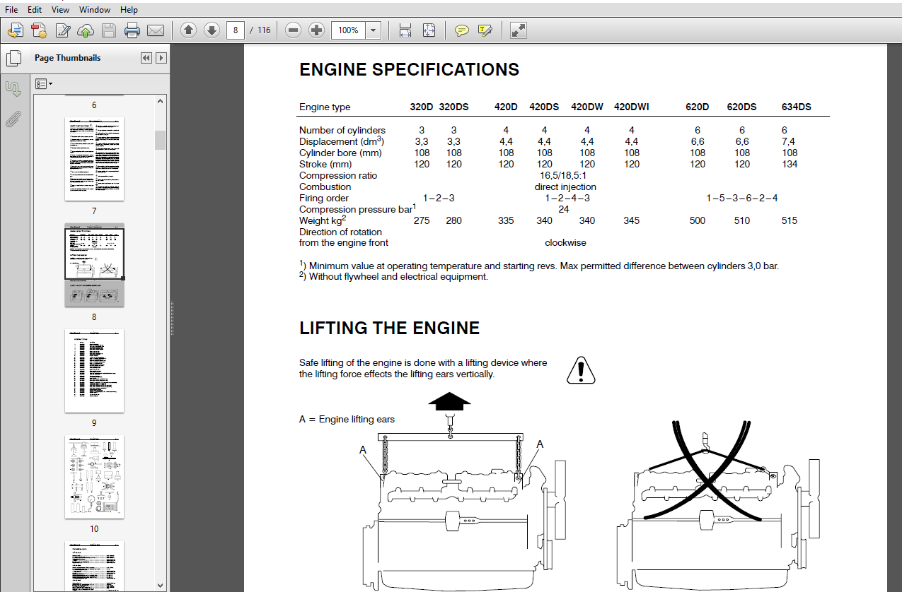
LIFTING THE ENGINE 0—3
LOCATION OF THE ENGINE SERIAL NO0—3
SPECIAL TOOLS0—4
TECHNICAL DATA 0—6
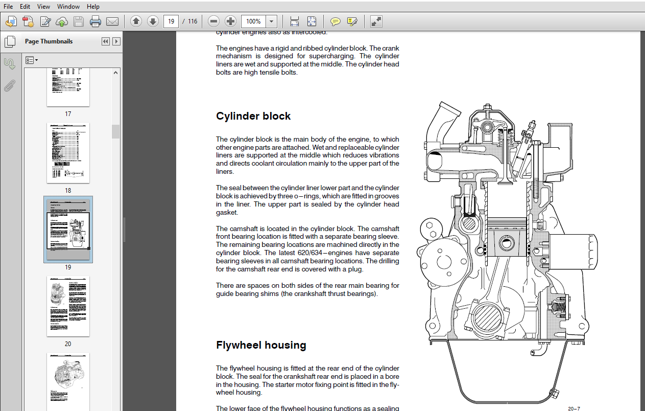
Cylinder block 0—6
Cylinder liner 0—6
Cylinder head0—6
Valves, rocker arms and tappets 0—7
Camshaft 0—7
Crankshaft0—8
Flywheel 0—8
Balancing unit0—9
Timing gears 0—9
Connecting rod 0—9
Piston, piston rings and pin0—10
Lubricating system 0—10
Oil pump (320, 420) 0—10
Oil pump (620, 634) 0—11
Coolant pump (320, 420) 0—11
Coolant pump (320, 420 separate ball bearings) 0—11
Coolant pump (620, 634) 0—12
Thermostat 0—12
Turbocharger0—12
TIGHTENING TORQUES 0—13
CONSTRUCTION0—14
General 0—14
Cylinder block 0—14
Flywheel housing0—14
Cylinder head0—15
Valve mechanism0—15
Crank mechanism 0—15
Timing gears 0—16
Lubricating system 0—17
Cooling system 0—18
Inlet and exhaust system 0—19
Electronic Engine Management system (EEM) 0—20
WORK INSTRUCTIONS
1 CYLINDER BLOCK
A Measuring cylinder liner wear 1—1
B Removing cylinder liner 1—1
C Checking cylinder block 1—1
D Changing camshaft bushing1—1
E Oversize bushings for camshaft1—2
F Fitting plug at camshaft rear end 1—3
G Fitting pipe for oil dipstick 1—4
H Fitting cylinder liner 1—4
2 FLYWHEEL HOUSING
A Fitting flywheel housing 2—1
B Changing crankshaft rear oil seal 2—1
3 CYLINDER HEAD
A Removing cylinder head3—1
B Removing valves 3—1
C Checking cylinder head 3—1
D Changing valve guides 3—2
E Machining valve seat3—2
F Changing valve seat ring3—3
G Grinding valves 3—3
H Fitting valves 3—3
I Fitting cylinder head 3—4
Contents 0—0
4 VALVE MECHANISM
A Reconditioning valve mechanism 4—1
B Changing camshaft/camshaft gear 4—2
C Adjusting valves 4—3
5 CRANKSHAFT
A Removing crankshaft5—1
B Checking crankshaft 5—1
C Changing crankshaft gears 5—1
D Changing crankshaft gear rim (420)5—2
E Fitting crankshaft 5—2
F Crankshaft hub piece5—3
G Changing crankshaft pulley/vibration damper 5—3
H Checking element of the rubber damper 5—4
I Viscose type vibration damper 5—4
6 CONNECTING RODS AND PISTONS
A Removing pistons together with connecting rods 6—1
B Changing connecting rod bearings6—1
C Checking connecting rod6—1
D Changing piston rings 6—3
E Checking pistons6—3
F Fitting piston pin 6—4
G Fitting piston together with connecting rod6—4
7 COUNTERBALANCE (420)
A Removing and disassembling counterbalance unit 7—1
B Reconditioning counterbalance unit7—1
C Fitting counterbalance unit 7—1
8 FLYWHEEL
A Changing starter ring gear on flywheel8—1
B Fitting flywheel8—1
9 TIMING GEAR ASSEMBLY
A Removing timing gear casing 9—1
B Reconditioning idler gear9—1
C Fitting timing gear casing9—2
D Idler gear with bevelled ball bearings 9—4
E Power take—off 9—5
10 LUBRICATION SYSTEM
A Reconditioning of oil relief valve for lubricatin oil pressure 10—1
B Removing and dismantling lubricating oil pump 10—1
C Assembling and fitting lubricating oil pump10—2
D Fitting oil sump gasket 10—3
E Lubricating oil cooler10—3
F Piston cooling nozzles (620, 634) 10—3
G Lubrication oil quality requirements10—4
11 COOLING SYSTEM
A Thermostat11—1
B Reconditioning coolant pump (320, 420) 11—1
C Reconditioning coolant pump (320, 420, 620, 634 separate ball bearings) 11—2
D Coolant pumps with heavy—duty bearings (620, 634)11—4
E Quality requirements of coolant11—4
12 INLET— AND EXHAUST SYSTEM
A Checking air cleaner 12—1
B Checking inlet and exhaust pipes 12—1
C Checking turbocharger 12—1
D Fitting turbocharger 12—2
13 FUEL SYSTEM
IN—LINE FUEL INJECTION PUMP
Technical data 13—1
A Bleeding fuel system13—6
B Bleeding Thermostart system 13—6
C Measuring fuel feed pressure 13—7
D Checking overflow valve13—7
E Changing fuel feed pump valves 13—7
F Checking injection timing13—8
G Adjusting fuel injection timing 13—9
Contents 0—0
H Removing fuel injection pump 13—10
I Fitting fuel injection pump 13—10
J Checking and changing pressure valve13—12
K Adjusting idling speed 13—12
L Removing injectors 13—13
M Inspecting injectors 13—13
N Reconditioning injectors 13—14
O Fitting injector in engine 13—15
P Fitting delivery pipes 13—15
CAV DISTRIBUTOR PUMP
Technical data 13—16
A Dismounting and mounting injection pump 13—17
B Injection pump gear 13—17
C Bleeding fuel system13—17
D Feed pump 13—18
E Injector13—18
STANADYNE DISTRIBUTOR PUMP
Technical data 13—19
A Removing pump 13—24
B Fitting injection pump and adjusting injection timing 13—24
C Bleeding fuel system13—25
D Fuel feed pump 13—25
E Injectors 13—25
F Adjusting low idling speed 13—26
G Bleeding Thermostart system 13—26
H Wiring diagram of electrical advance (CCA) 13—26
I Checking injection timing (dynamic) 13—27
Fuel quality requirement13—29
14 EQUIPMENT AND FEEDING TABLES
15 ELECTRICAL SYSTEM
A Alternators15—1
B Starters15—4
C Electric stop device 15—7
D Installation of magnetic pick up 15—9
E Temperature sensor 15—9
16 OPTIONAL EQUIPMENT
A Compressor (Bendix)16—1
B Compressor (Knorr) 16—2
C Industrial clutch (AP Borg & Beck)16—3
PLEASE NOTE:
- This is not a physical manual but a digital manual – meaning no physical copy will be couriered to you. The manual can be yours in the next 2 mins as once you make the payment, you will be directed to the download page IMMEDIATELY.
- This is the same manual used by the dealers inorder to diagnose your vehicle of its faults.
- Require some other service manual or have any queries: please WRITE to us at [email protected]


