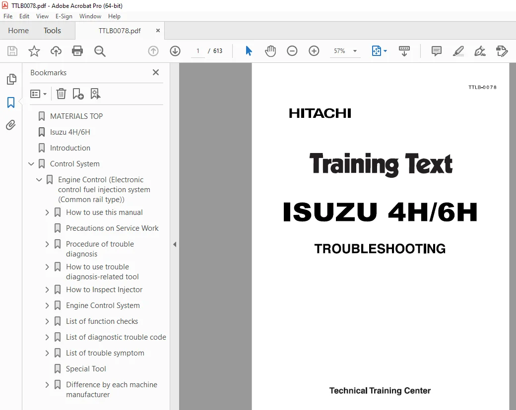
Isuzu Hitachi 4H/6H Engine Troubleshooting Training Text Manual TTLB-0078 PDF
$31.95
Isuzu Hitachi 4H/6H Engine Troubleshooting Training Text Manual TTLB-0078 – PDF DOWNLOAD
Description
Isuzu Hitachi 4H/6H Engine Troubleshooting Training Text Manual TTLB-0078 – PDF DOWNLOAD
FILE DETAILS:
Isuzu Hitachi 4H/6H Engine Troubleshooting Training Text Manual TTLB-0078 – PDF DOWNLOAD
Language : English
Pages : 613
Downloadable : Yes
File Type : PDF
IMAGES PREVIEW OF THE MANUAL:
TABLE OF CONTENTS:
Isuzu Hitachi 4H/6H Engine Troubleshooting Training Text Manual TTLB-0078 – PDF DOWNLOAD
MATERIALS TOP 0
Isuzu 4H/6H 1
Introduction 2
Control System 4
Engine Control (Electronic control fuel injection system (Common rail type)) 4
How to use this manual 6
Table of abbreviation 7
List of parts according to engine control specifications 8
About colors of wirings 9
About wiring diagrams 10
How to read trouble diagnosis section 11
Precautions on Service Work 13
Procedure of trouble diagnosis 14
Information: 15
Interview 16
Pre-inspection 18
Information: 18
Trouble Diagnosis 18
Description of terms 18
How to read DTC 19
Confirmation after repair 21
List of final check items 21
How to clear DTC 22
Trouble diagnosis with scan tool 23
About scan tool display 24
How to use trouble diagnosis-related tool 28
How to use Tech2 28
Components of Tech2 28
Each part of Tech2 29
Precautions on handling Tech2 30
Power supply 32
Check items before use 33
How to connect Tech2 33
Operation procedure 34
List of functions of Tech2 36
Diagnostic procedure 37
DTC application menu display screen 39
Data Display 40
Snapshot 41
Actuator test 45
Injector balance test 46
View captured data 48
Tool options 50
Rewrite setting of Q adjust data by Tech2 51
Injector ID code (No 1 cylinder – No 6 cylinder) registration setting using Tech2 58
ID code upload (Tech2) 66
ID code download (Tech2) 68
How to use TIS 2000 71
TIS 2000 installation procedure 71
How to display snapshot 73
Software download 78
How to Inspect Injector 81
How to use injector checker 81
Components of injector checker 81
Method to identify using non-contact infrared thermometer 85
How to use flash tool 87
Refer to related documents 87
How to use breaker box 88
Breaker box inspection procedure 88
How to connect breaker box 88
Example of use for breaker box 89
Engine Control System 91
Description of function and operation 91
About engine control (common rail) system 91
System control schematic diagram 91
Table of Input/Output 93
Electronic control fuel injection system (Common rail type) 93
System schematic diagram 95
Fuel system 96
EGR (Exhaust gas recirculation) 96
Idling control 98
Speed limit control 98
Engine speed output to tachometer 99
Preheating control 100
Engine Control Module (ECM) 100
Engine component location diagram 102
Supply pump 104
SCV (suction control valve) 104
Fuel temperature (FT) sensor 105
Common rail 106
Flow damper 106
Pressure limiter 107
Common rail pressure sensor 107
Injector 108
Engine coolant temperature (ECT) sensor 108
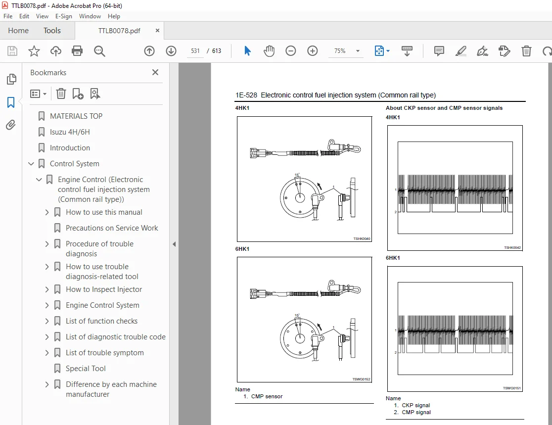
Crankshaft position (CKP) sensor 109
Camshaft position (CMP) sensor 110
Engine oil pressure sensor 111
Accelerator position (AP) sensor 111
Intake air temperature (IAT) sensor 112
EGR position sensor 112
Boost pressure sensor 113
Boost temperature sensor 113
Diagnosis lamp 114
DLC (data link connector) 114
Diagnostic switch 114
Memory clear switch 114
Mode selector switch (1, 2, 3) 114
Wiring diagram of engine control module (ECM) 115
Pin arrangement of engine control module (ECM) 117
Circuit diagram 121
Main relay circuit 121
Starter for ECM control, glow circuit 122
Starter for safety relay, glow circuit 124
CAN, GND, DLC circuits 126
Indicator lamp, tachometer circuit 127
Injector circuit 128
SCV circuit 130
CKP sensor, vehicle speed sensor, fuel temperature sensor, engine coolant temperature sensor, engine oil pressure sensor circuit 131
Boost temperature sensor, boost pressure sensor circuit 132
CMP sensor, common rail pressure sensor, EGR circuit 133
Accelerator position sensor, barometric pressure sensor, intake air temperature sensor circuit 134
Idling selector switch, idle up switch, idle down switch, mode map switch circuit 135
Memory clear switch, engine stop switch circuit 136
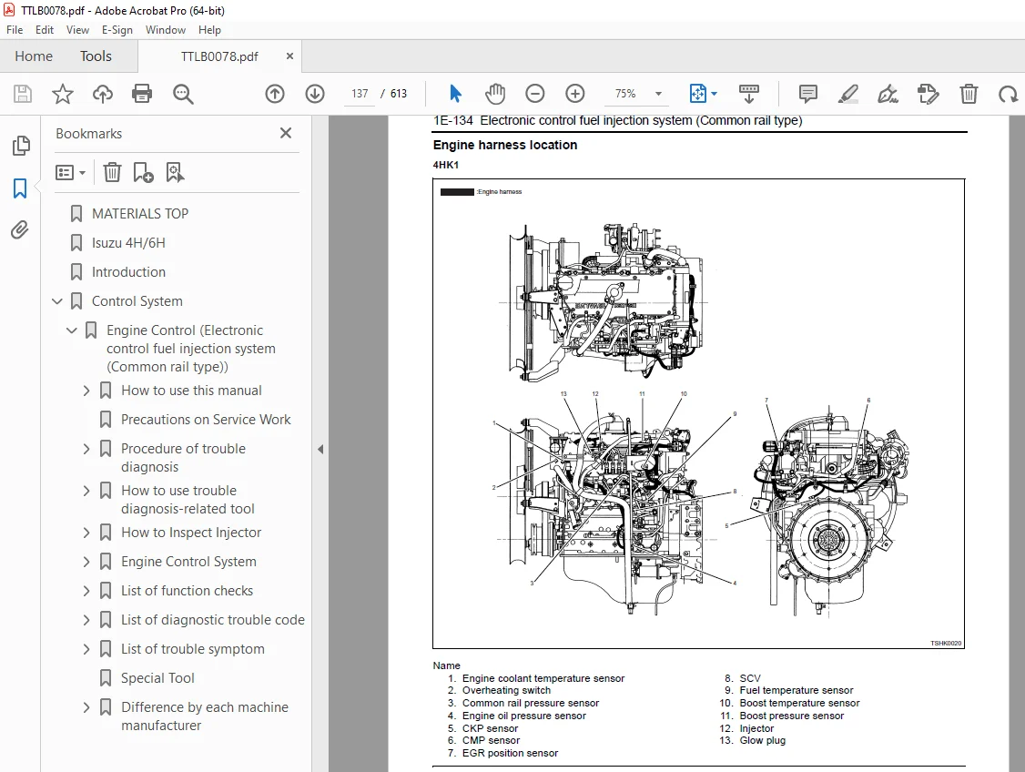
Engine harness location 137
H94/H95 connector 148
Connector list 149
List of function checks 152
OBD system check 153
Diagnosis lamp illumination circuit system check 155
Diagnosis lamp blinking circuit system check 157
Scan tool power supply circuit system check 160
Scan tool communication circuit system check 162
Starting circuit system check 165
Starting system check 171
Fuel system check 174
Intake system check 176
Exhaust system check 177
EGR control system check 178
QOS system check 181
List of diagnostic trouble code 186
DTC: P0087 (Flash code 227) Common rail low pressure fault (No pressure feed in supply pump) 210
DTC: P0088 (Flash code 118) Common rail pressure is abnormally high (1st or 2nd stage) 218
DTC: P0089 (Flash code 151) Common rail pressure fault (Excessive pressure feed in supply pump) 223
DTC: P0090 (Flash code 247) SCV drive system open circuit, +B short or ground short 228
DTC: P0107 (Flash code 71) Barometric pressure sensor circuit input is low (open circuit or ground short) 234
DTC: P0108 (Flash code 71) Barometric pressure sensor circuit input is high (+5 V short) 241
DTC: P0112 (Flash code 22) Intake air temperature sensor fault (low voltage fault, GND short, short circuit) 248
DTC: P0113 (Flash code 22) Intake air temperature sensor fault (high voltage fault, open circuit or short to power supply circuit) 254
DTC: P0117 (Flash code 23) Engine coolant temperature sensor fault (low voltage fault, GND short, short circuit) 262
DTC: P0118 (Flash code 23) Engine coolant temperature sensor input is high (open circuit or short to power supply) 269
DTC: P0182 (Flash code 211) Fuel temperature sensor fault (low voltage fault, GND short) 277
DTC: P0183 (Flash code 211) Fuel temperature sensor fault (high voltage fault, open circuit or short to power supply circuit) 283
DTC: P0192 (Flash code 245) Common rail pressure sensor fault (low voltage fault, short circuit) 291
DTC: P0193 (Flash code 245) Common rail pressure sensor fault (high voltage fault) 297
DTC: P0201 (Flash code 271) Open circuit in injection nozzle #1 drive system 304
DTC: P0202 (Flash code 272) Open circuit in injection nozzle #2 drive system 311
DTC: P0203 (Flash code 273) Open circuit in injection nozzle #3 drive system 318
DTC: P0204 (Flash code 274) Open circuit in injection nozzle #4 drive system 325
DTC: P0205 (Flash code 275) Open circuit in injection nozzle #5 drive system 332
DTC: P0206 (Flash code 276) Open circuit in injection nozzle #6 drive system 337
DTC: P0219 (Flash code 543) Overrun 342
DTC: P0237 (Flash code 32) Boost sensor pressure fault (low voltage fault, open circuit) 344
DTC: P0238 (Flash code 32) Boost pressure sensor fault (high voltage fault, short to power supply circuit, ground open circuit) 351
DTC: P0335 (Flash code 15) Crank sensor fault (no signal) 358
DTC: P0336 (Flash code 15) Crank sensor fault (signal fault) 365
DTC: P0340 (Flash code 14) Cam sensor fault (no signal) 371
DTC: P0341 (Flash code 14) Cam sensor fault (signal fault) 378
DTC: P0380 (Flash code 66) Glow relay circuit fault 384
DTC: P0381 (Flash code 67) Glow plug lamp circuit fault 389
DTC: P0487 (Flash code 44) EGR position sensor fault 394
DTC: P0488 (Flash code 45) EGR valve control fault 400
DTC: P0522 (Flash code 294) Engine oil pressure sensor fault (low voltage fault, open circuit, ground short) 406
DTC: P0523 (Flash code 295) Engine oil pressure sensor fault (high voltage fault, short to power supply, ground short) 412
DTC: P0601 (Flash code 53) ROM fault 420
DTC: P0603 (Flash code 54) EEPROM fault 422
DTC: P0606 (Flash code 51/52) CPU fault 424
DTC: P0611 (Flash code 34) Charge circuit fault (bank 1) 426
DTC: P0612 (Flash code 34) Charge circuit fault (bank 2) 429
DTC: P0650 (Flash code 77) Diagnosis lamp circuit fault 432
DTC: P1093 (Flash code 227) No pump pressure feed 437
DTC: P1095 (Flash code 225) Pressure limiter open 446
DTC: P1112 (Flash code 295) Boost temperature sensor fault (low voltage fault, ground short) 455
DTC: P1113 (Flash code 295) Boost temperature sensor fault (high voltage fault, open circuit, short to power supply circuit) 463
DTC: P1173 (Flash code 542) Overheat 469
DTC: P1225 (Flash code 31) Idle UP/DOWN switch fault 475
DTC: P1261 (Flash code 158) Injection nozzle common 1 drive system fault 479
DTC: P1262 (Flash code 159) Injection nozzle common 2 drive system fault 490
DTC: P1271 (Flash code 24) Accelerator sensor 1-2 comparison fault 501
DTC: P1277 (Flash code 24) Accelerator sensor 1 fault (low voltage fault) 507
DTC: P1278 (Flash code 24) Accelerator sensor 1 fault (high voltage fault) 512
DTC: P1282 (Flash code 24) Accelerator sensor 2 fault (low voltage fault) 517
DTC: P1283 (Flash code 24) Accelerator sensor 2 fault (high voltage fault) 522
DTC: P1345 (Flash code 16) Cam sensor out of phase 527
DTC: P1625 (Flash code 416) Main relay fault 532
DTC: P1630 (Flash code 36) A/D conversion fault 539
DTC: P1631 (Flash code 55) Voltage fault in 5-V power supply 1 541
DTC: P1632 (Flash code 55) Voltage fault in 5-V power supply 2 544
DTC: P1633 (Flash code 55) Voltage fault in 5-V power supply 3 547
DTC: P1634 (Flash code 55) Voltage fault in 5-V power supply 4 550
DTC: P1635 (Flash code 55) Voltage fault in 5-V power supply 5 553
DTC: U2104 (Flash code 84) CAN Bus fault 556
DTC: U2106 (Flash code 85) CAN timeout fault 561
List of trouble symptom 566
Engine start failure 567
Engine stall 571
Engine hunting, rough idling 575
Engine output shortage 579
Exhaust gas contains a lot of white smoke 584
Exhaust gas contains a lot of black smoke 587
Noise 590
Fuel consumption deteriorates 592
Oil consumption deteriorates 595
Special Tool 597
Difference by each machine manufacturer 598
Hitachi Construction Machinery Co , Ltd 598
About wiring diagrams 601
Tech2 reference value 607
DESCRIPTION:
Isuzu Hitachi 4H/6H Engine Troubleshooting Training Text Manual TTLB-0078 – PDF DOWNLOAD
Introduction:
- This Troubleshooting Manual describes the structure and the troubleshooting of
electronic control fuel injection system (common rail type) in 4HK1 and 6HK1
industrial engines. - Use this manual sufficiently to perform service work properly and quickly.
How to use this manual:
- This manual describes about engine-related trouble diagnosis, and is closely related
to the machine trouble diagnosis. Always refer to both manuals for the trouble
diagnosis. - This manual consists of the following contents. This section “How to use this manual”
describes about abbreviations and instructions to use this manual. Therefore, if you
are familiar with Isuzu manuals, start with Precautions on service work and Basic
procedure of trouble diagnosis.
How to use this manual
• Table of abbreviation
• List of parts according to engine control specifications
• Wiring color code
• How to use wiring diagram
S.V 05/01/2025