

Hyundai R180W-9S Wheel Excavator workshop Service Manual
TABLE OF CONTENTS:
Hyundai R180W-9S Wheel Excavator workshop Service Manual
WHEELED EXCAVATOR R180W-9S |
FOREWORD | ||||
CONTENTS | ||||
SECTION 1 | ||||
| GENERAL | ||||
| Group 1 | Safety Hints | |||
| Group 2 | Specifications | |||
| SECTION 2 | ||||
| STRUCTURE AND FUNCTION | ||||
| Group 1 | Pump Device | |||
| Group 2 | Main Control Valve | |||
| Group 3 | Swing Device | |||
| Group 4 | Travel Device | |||
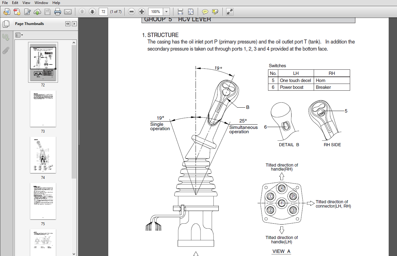
| Group 5 | RCV Lever | |||
| Group 6 | Accelerator Pedal | |||
| Group 7 | Brake Pedal | |||
| Group 8 | Transmission | |||
| Group 9 | Travel control valve | |||
| Group 10 | Steering Valve | |||
| SECTION 3 | ||||
| HYDRAULIC SYSTEM | ||||
| Group 1 | Hydraulic Circuit | |||
| Group 2 | Main Circuit | |||
| Group 3 | Pilot Circuit | |||
| Group 4 | Single Operation | |||
| Group 5 | Combined Operation | |||
| SECTION 4 | ||||
| ELECTRICAL SYSTEM | ||||
| Group 1 | Component Location | |||
| Group 2 | Electrical Circuit | |||
| Group 3 | Electrical Component Specification | |||
| Group 4 | Connectors | |||
| SECTION 5 | ||||
| MECHATROMICS SYSTEM | ||||
| Group 1 | Outline | |||
| Group 2 | Mode selection System | |||
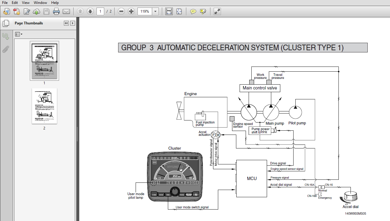
| Group 3 | Automatic Deceleration System | |||
| Group 4 | Power Boost System | |||
| Group 5 | Travel Speed Control System | |||
| Group 6 | Automatic Warming Up Function | |||
| Group 7 | Engine Overheat Prevention System | |||
| Group 8 | Variable Power Control System | |||
| Group 9 | Attachment Flow ControlSystem | |||
| Group 10 | Anti-Restartl System | |||
| Group 11 | Self-Diagnostic System | |||
| Group 12 | Engine control System | |||
| Group 13 | EPPR Valve | |||
| Group 14 | Monitoring System | |||
| Group 15 | Fuel Warmer System | |||
| SECTION 6 | ||||
| TROUBLESHOOTING | ||||
| Group 1 | Before troubleshooting | |||
| Group 2 | Hydraulic and Mechanical System | |||
| Group 3 | Electrical System | |||
| Group 4 | Mechatronics System | |||
| SECTION 7 | ||||
| MAINTENANCE STANDARD | ||||
| Group 1 | Operational Performance Test | |||
| Group 2 | Major Components | |||
| Group 3 | Work Equipment | |||
| SECTION 8 | ||||
| DISASSEMBLY AND ASSEMBLY | ||||
| Group 1 | Precaution | |||
| Group 2 | Tightening Torque | |||
| Group 3 | Pump Device | |||
| Group 4 | Main Control Valve | |||
| Group 5 | Swing Device (Type 1) | |||
| Swing Device (Type 2) | ||||
| Group 6 | Travel Motor | |||
| Group 7 | Transmission | |||
| Group 8 | Steering Valve | |||
| Group 9 | Front Axle | |||
| Front axle special tool | ||||
| Group 10 | Rear Axle | |||
| Rear axle special tool | ||||
| Group 11 | RCV Lever | |||
| Group 12 | Turning Joint | |||
| Group 13 | Boom, Arm, Bucket, Dozer and Outrigger Cylinders | |||
| Group 14 | Work Equipment | |||
| SECTION 9 | ||||
| COMPONENT MOUNTING TORQUE | ||||
| Group 1 | Introduction guide | |||
| Group 2 | Engine system | |||
| Group 3 | Electric system | |||
| Group 4 | Hydraulic system | |||
| Group 5 | Power train system | |||
| Group 6 | Structure | |||
| Group 7 | Work equipment | |||
DESCRIPTION:
Hyundai R180W-9S Wheel Excavator workshop Service Manual
1. STRUCTURE:
This service manual has been prepared as an aid to improve the quality of repairs by giving the serviceman an accurate understanding of the product and by showing him the correct way to perform repairs and make judgements. Make sure you understand the contents of this manual and use it to full effect at every opportunity. This service manual mainly contains the necessary technical information for operations performed in a service workshop. For ease of understanding, the manual is divided into the following sections.
SECTION 1 GENERAL:
This section explains the safety hints and gives the specification of the machine and major components.
SECTION 2 STRUCTURE AND FUNCTION:
This section explains the structure and function of each component. It serves not only to give an understanding of the structure, but also serves as reference material for troubleshooting.
SECTION 3 HYDRAULIC SYSTEM:
This section explains the hydraulic circuit, single and combined operation.
SECTION 4 ELECTRICAL SYSTEM:
This section explains the electrical circuit, monitoring system and each component. It serves not only to give an understanding electrical system, but also serves as reference material for trouble shooting.
SECTION 5 MECHATRONICS SYSTEM:
This section explains the computer aided power optimization system and each component.
SECTION 6 TROUBLESHOOTING:
This section explains the troubleshooting charts correlating problems to causes.
SECTION 7 MAINTENANCE STANDARD:
This section gives the judgement standards when inspecting disassembled parts.
SECTION 8 DISASSEMBLY AND ASSEMBLY:
This section explains the order to be followed when removing, installing, disassembling or assembling each component, as well as precautions to be taken for these operations.
SECTION 9 COMPONENT MOUNTING TORQUE:
- This section shows bolt specifications and standard torque values needed when mounting components to the machine.
- The specifications contained in this shop manual are subject to change at any time and without any advance notice. Contact your HYUNDAI distributor for the latest information.
VIDEO PREVIEW OF THE MANUAL:

IMAGES PREVIEW OF THE MANUAL:
PLEASE NOTE:
- This is the same manual used by the dealers to diagnose and troubleshoot your vehicle
- You will be directed to the download page as soon as the purchase is completed. The whole payment and downloading process will take anywhere between 2-5 minutes
- Need any other service / repair / parts manual, please feel free to contact [email protected] . We still have 50,000 manuals unlisted


Cassius Uriah –
Can you please send me the download link to the manual?