

Hitachi ZX240-5G ZX240LC-5G ZX250H-5G ZX250LCH-5G Hydraulic Excavator Operational Principle Manual
File Details:
Hitachi ZX240-5G ZX240LC-5G ZX250H-5G ZX250LCH-5G Hydraulic Excavator Operational Principle Manual
- Manual Language:English
- Pages:348
- Size: 13.0 MB
- Downloadable:Yes
- Format:PDF
Video Preview:

Image Preview:
Description:
Hitachi ZX240-5G ZX240LC-5G ZX250H-5G ZX250LCH-5G Hydraulic Excavator Operational Principle Manual
TO THE READER
This manual is written for an experienced technician to provide technical information needed to maintain and repair this machine. The machine specification and description according to destination may be explained on this manual.
• Be sure to thoroughly read this manual for correct product information and service procedures.
• If you have any questions or comments, at if you found any errors regarding the contents of this manual, please contact using “Service Manual Revision Request Form” at the end of this manual.
ADDITIONAL REFERENCES
Please refer to the other materials (operator’s manual, parts catalog, engine technical material and Hitachi training material etc.) in addition to this manual.
MANUAL COMPOSITION
This manual consists the Technical Manual and the Workshop Manual.
• Information included in the Technical Manual: technical information needed for redelivery and delivery, operation and activation of all devices and systems, operational performance tests, and troubleshooting procedures.
• Information included in the Workshop Manual: technical information needed for maintenance and repair of the machine, tools and devices needed for maintenance and repair, maintenance standards, and removal/installation and assemble/ disassemble procedures.
Table Of Contents:
Hitachi ZX240-5G ZX240LC-5G ZX250H-5G ZX250LCH-5G Hydraulic Excavator Operational Principle Manual
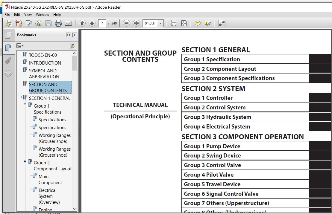
TODCE-EN-00................................................................................................................................................................  1
INTRODUCTION...............................................................................................................................................................  3
SYMBOL AND ABBREVIATION....................................................................................................................................................  5
SECTION AND GROUP CONTENTS.................................................................................................................................................  7
SECTION 1 GENERAL..........................................................................................................................................................  9
	Group 1 Specifications................................................................................................................................................. 11
		Specifications..................................................................................................................................................... 11
		Specifications..................................................................................................................................................... 12
		Working Ranges (Grouser shoe)...................................................................................................................................... 13
		Working Ranges (Grouser shoe)...................................................................................................................................... 14
	Group 2 Component Layout............................................................................................................................................... 15
		Main Component..................................................................................................................................................... 15
		Electrical System (Overview)....................................................................................................................................... 16
		Engine............................................................................................................................................................. 17
		Electrical System (In Cab)......................................................................................................................................... 17
		Electrical System (Rear Tray)...................................................................................................................................... 18
		Electrical System (Switch Panel)................................................................................................................................... 19
		Electrical System (Around Air Cleaner)............................................................................................................................. 20
		Electrical System (Relays)......................................................................................................................................... 21
		Pump Device........................................................................................................................................................ 22
		Control Valve...................................................................................................................................................... 23
		Signal Control Valve............................................................................................................................................... 23
		Swing Device....................................................................................................................................................... 25
		Travel Device...................................................................................................................................................... 25
		3-Spool Solenoid Valve Unit........................................................................................................................................ 26
		Layout of Attachment Spec. Parts................................................................................................................................... 28
	Group 3 Component Specifications....................................................................................................................................... 33
		Engine............................................................................................................................................................. 33
		Engine Accessories................................................................................................................................................. 37
		Hydraulic Component................................................................................................................................................ 38
		Electrical Component............................................................................................................................................... 42
SECTION 2 SYSTEM........................................................................................................................................................... 45
	Group 1 Controller..................................................................................................................................................... 47
		Outline............................................................................................................................................................ 47
		CAN Circuit........................................................................................................................................................ 48
	Group 2 Control System................................................................................................................................................. 51
		Outline............................................................................................................................................................ 51
		Engine Control..................................................................................................................................................... 54
		Pump Control....................................................................................................................................................... 80
		Valve Control...................................................................................................................................................... 90
		Other Control......................................................................................................................................................106
	Group 3 Hydraulic System...............................................................................................................................................111
		Outline............................................................................................................................................................111
		Pilot Circuit......................................................................................................................................................112
		Main Circuit.......................................................................................................................................................122
	Group 4 Electrical System..............................................................................................................................................137
		Outline............................................................................................................................................................137
		Main Circuit.......................................................................................................................................................138
		Electric Power Circuit (Key Switch: OFF)...........................................................................................................................140
		CAN Circuit........................................................................................................................................................142
		Accessory Circuit..................................................................................................................................................144
		Preheating Circuit (Key Switch: ON, START).........................................................................................................................146
		Starting Circuit (Key Switch: START)...............................................................................................................................148
		Charging Circuit (Key Switch: ON)..................................................................................................................................152
		Surge Voltage Prevention Circuit...................................................................................................................................156
		Pilot Shut-Off Circuit (Key switch: ON)............................................................................................................................158
		Engine Stop Circuit................................................................................................................................................160
		Monitor Circuit....................................................................................................................................................163
		Security Circuit...................................................................................................................................................164
		Radio Circuit......................................................................................................................................................166
		Air Conditioner Circuit............................................................................................................................................166
		Accessory Circuit..................................................................................................................................................169
		Work Light Circuit.................................................................................................................................................170
		Wiper/Washer Circuit...............................................................................................................................................172
		Cab Light Circuit..................................................................................................................................................174
SECTION 3 COMPONENT OPERATION..............................................................................................................................................179
	Group 1 Pump Device....................................................................................................................................................181
		Outline............................................................................................................................................................181
		Main Pump..........................................................................................................................................................182
		Regulator..........................................................................................................................................................186
		Solenoid Valve.....................................................................................................................................................204
		Pilot Pump.........................................................................................................................................................206
		Pump Delivery Pressure Sensor......................................................................................................................................206
		Pump Control Pressure Sensor.......................................................................................................................................206
		N Sensor (Engine Speed Sensor).....................................................................................................................................207
	Group 2 Swing Device...................................................................................................................................................209
		Outline............................................................................................................................................................209
		Swing Reduction Gear...............................................................................................................................................210
		Swing Motor........................................................................................................................................................211
		Swing Parking Brake................................................................................................................................................212
		Valve Unit.........................................................................................................................................................214
	Group 3 Control Valve..................................................................................................................................................217
		Outline............................................................................................................................................................217
		Hydraulic Circuit..................................................................................................................................................238
		Flow Combiner Valve................................................................................................................................................244
		Main Relief Valve..................................................................................................................................................246
		Overload Relief Valve (with Make-Up Function)......................................................................................................................250
		Regenerative Valve.................................................................................................................................................254
		Anti-Drift Valve...................................................................................................................................................258
		Flow Rate Control Valve............................................................................................................................................262
		Digging Regenerative Valve.........................................................................................................................................266
		Boom Lower Meter-In Cut Valve......................................................................................................................................268
		Auxiliary Flow Combiner Valve and Bypass Shut-Out Valve............................................................................................................270
	Group 4 Pilot Valve....................................................................................................................................................275
		Outline............................................................................................................................................................275
		Operation (Front Attachment / Swing and Travel Pilot Valves).......................................................................................................277
		Operation (Auxiliary Pilot Valve)..................................................................................................................................285
		Shockless Function (Only for Travel Pilot Valve)...................................................................................................................290
	Group 5 Travel Device..................................................................................................................................................291
		Outline............................................................................................................................................................291
		Travel Reduction Gear..............................................................................................................................................292
		Travel Motor.......................................................................................................................................................294
		Parking Brake......................................................................................................................................................296
		Travel Brake Valve.................................................................................................................................................298
		Overload Relief Valve..............................................................................................................................................302
		Travel Mode Control................................................................................................................................................304
	Group 6 Signal Control Valve...........................................................................................................................................309
		Outline............................................................................................................................................................309
		Pilot Port.........................................................................................................................................................310
		Shuttle Valve......................................................................................................................................................315
		Shockless Valve....................................................................................................................................................318
		Pump 1 and 2 Flow Rate Control Valve...............................................................................................................................322
		Bucket Flow Rate Control Valve Control Spool, Flow Combiner Valve Control Spool, Swing Parking Brake Release Spool, Arm 1 Flow Rate Control Valve Control Spool....324
	Group 7 Others (Upperstructure)........................................................................................................................................327
		Pilot Shut-Off Solenoid Valve......................................................................................................................................327
		Solenoid Valve.....................................................................................................................................................329
		Pilot Relief Valve.................................................................................................................................................332
		EC Motor...........................................................................................................................................................332
		Hose Rupture Valve.................................................................................................................................................334
	Group 8 Others (Undercarriage).........................................................................................................................................341
		Swing Bearing......................................................................................................................................................341
		Center Joint.......................................................................................................................................................342
		Track Adjuster (Front Idler Integrated Type).......................................................................................................................343
SERVICE MANUAL REVISION REQUEST FORM.......................................................................................................................................347
Please Note:
⦁ This is the same manual used by the dealers to diagnose and troubleshoot your vehicle
⦁ You will be directed to the download page as soon as the purchase is completed. The whole payment and downloading process will take anywhere between 2-5 minutes
⦁ Need any other service / repair / parts manual, please feel free to contact [email protected] . We still have 50,000 manuals unlisted


