Hitachi ZX 690LCH-7 690LCR-7 Hydraulic Excavator Operational Technical Manual PN:TTJBQ40 PDF
$28.95
Hitachi ZX 690LCH-7 690LCR-7 Hydraulic Excavator Operational Technical Manual PNTTJBQ40 – PDF DOWNLOAD
Description
Hitachi ZX 690LCH-7 690LCR-7 Hydraulic Excavator Operational Technical Manual PNTTJBQ40 – PDF DOWNLOAD
FILE DETAILS:
Hitachi ZX 690LCH-7 690LCR-7 Hydraulic Excavator Operational Technical Manual PNTTJBQ40 – PDF DOWNLOAD
Language :English
Pages :397
Downloadable : Yes
File Type : PDF
IMAGES PREVIEW OF THE MANUAL:
DESCRIPRION:
Hitachi ZX 690LCH-7 690LCR-7 Hydraulic Excavator Operational Technical Manual PNTTJBQ40 – PDF DOWNLOAD
This manual is written for an experienced technician to provide technical information needed to maintain and repair this machine.
The machine specification and description according to destination may be explained on this manual.
●Be sure to thoroughly read this manual for correct product information and service procedures.
●If you have any questions or comments, at if you found any errors regarding the contents of this manual, please contact using “Service Manual Revision Request Form” at the end of this manual. (Note: Do not tear off the form. Copy this form for usage.)
•Service Material Development Center Hitach Construction Machinery Co., Ltd.
•TEL: 81-29-832-9673
•FAX: 81-29-831-1162
•E-mail: [email protected]
All information, illustrations and specifications in this manual are based on the latest product information available at the time of publication. The right is reserved to make changes at any time without notice.
Additional References
Please refer to the other materials (operator’s manual, parts catalog, engine technical material and Hitachi training material etc.) in addition to this manual.
Manual Composition
This manual consists the Technical Manual, the Workshop Manual and the Engine Manual.
●Information included in the Technical Manual: Technical information needed for redelivery and delivery
•Operation and activation of all devices and systems, operational performance tests, and troubleshooting procedures.
●Information included in the Workshop Manual: Technical information needed for maintenance and repair of the machine
•Tools and devices needed for maintenance and repair, maintenance standards, and removal / installation and assemble / disassemble procedures
●Information included in the Engine Manual: Technical information needed for redelivery and delivery and maintenance and repair of the machine
•Operation and activation of all devices and systems, troubleshooting and assemble / disassemble procedures
TABLE OF CONTENTS:
Hitachi ZX 690LCH-7 690LCR-7 Hydraulic Excavator Operational Technical Manual PNTTJBQ40 – PDF DOWNLOAD
TOJBQ40-EN-00 1
INTRODUCTION 3
To The Reader 3
Additional References 3
Manual Composition 3
Page Number 3
Trademark 4
Safety Alert Symbol and Headline Notations 4
Units Used 4
SYMBOL AND ABBREVIATION 7
Symbol and Abbreviation 7
CONTRASTING LIST OF PART NAME 9
Contrasting List of Part Name between Technical Manual and Parts Catalog 9
SECTION AND GROUP CONTENTS 11
CONTENTS 13
GENERAL 21
Specifications 23
Specifications ZX690LCH-7, 690LCR-7 23
Working Ranges ZX690LCH-7, 690LCR-7 24
Component Layout 25
Main Component (Upperstructure) 25
Main Component (Undercarriage) 27
Main Component (Front Attachment) 28
Electrical System (Overview) 29
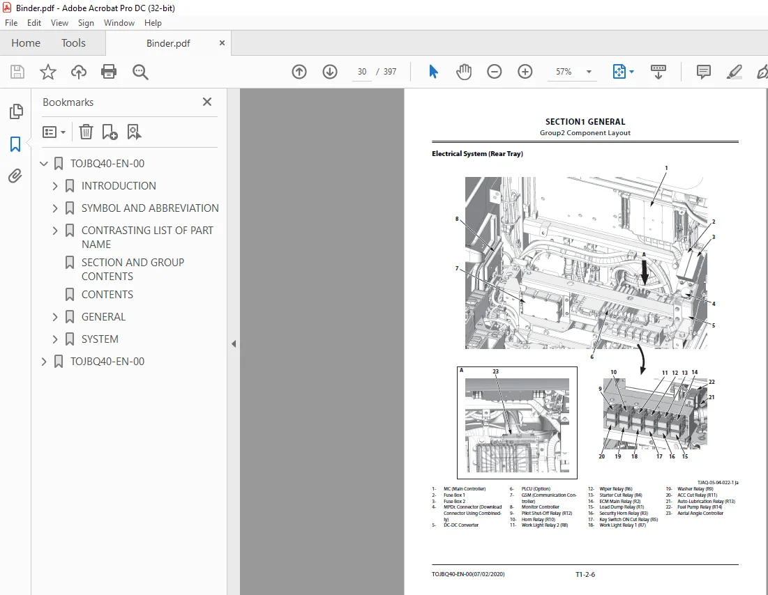
Electrical System (Rear Tray) 30
Electrical System (Switches) 31
Electrical System (Utility Space) 32
Electrical System (Around Battery) 33
Engine Oil Monitoring Sensor and Engine Oil Filter 33
Hydraulic Oil Monitoring Sensor 34
Engine 35
Aftertreatment Device 36
Pump Device 37
Control Valve 38
Signal Control Valve 38
Pilot Check Valve 39
Swing Device 40
Travel Device 40
4-Spool Solenoid Valve Unit (Control Valve Side) 41
4-Spool Solenoid Valve Unit (Hydraulic Oil Tank Side) 41
Expansion Tank 42
Air Cleaner 42
DEF Tank 43
DEF Supply Module 43
Coolant Control Valve 44
Electric Fuel Pump and Fuel Filter 44
Radiator Fan Valve and Radiator Fan Motor 45
Oil Cooler Fan Valve and Oil Cooler Fan Motor 46
Shockless Valve 46
Radiator Fan Valve 47
Oil Cooler Fan Valve 47
Boom Upper Area 48
Arm Upper Area 48
Distribution Valve (Upperstructure) 49
Auto-Lubrication Device 49
Component Specifications 51
Specifications of Engine 51
Specifications of Engine Accessories 52
Specifications of Hydraulic Component 53
Specifications of Electrical Component 54
SYSTEM 57
Controller 59
Outline of Controller 59
CAN Circuit 59
Control System 61
Outline of Control System 61
Engine Control 61
Engine Control System Layout 62
Engine Protection Control 63
Engine Control Dial Control 65
ECO Control 67
Power Mode (ECO/PWR/HP Mode) Switch Control 69
ECO/PWR Mode Travel Speed Increase Control 71
Auto-Idle Control 73
Radiator Coolant Temperature Auto-Warming Up Control 75
Engine Speed Slow Down Control 77
One-Touch Idle Control (Option) 79
Pump Control 81
Pump Control System Layout 82
Pump Flow Rate Control 83
Engine Control Dial Output Control 85
Speed Sensing Control 87
Output Power Control 90
ECO/PWR Mode Control 92
Relief Flow Rate Decrease Control 94
Swing High Pressure Power Decrease Control 96
Overheat Prevention Control 98
Attachment Operation Pump Control (Option)100
Radiator Fan Pump Flow Rate Control (Air Conditioner Switch: OFF)102
Radiator Fan Pump Flow Rate Control (Air Conditioner Switch: ON)104
Pump and Valve Learning Control106
Pump Torque Restriction Control108
Valve Control (Standard)110
Valve Control (Standard) System Layout111
Pressure Rising Selection Control When Traveling112
Power Digging Control114
Auto-Power Lift Control116
Travel Motor Displacement Angle Control118
Boom Mode Selector Control120
Swing Flow Rate Control122
Arm 2 Flow Rate Control124
Bucket Flow Combiner Control126
Aftertreatment Device Manual Regeneration Control128
Aftertreatment Device Auto Regeneration Control130
Engine Protection Control at Low Temperature132
Oil Cooler Fan Rotation Control134
Radiator Fan and Oil Cooler Fan Reverse Rotation Control136
Arm Regenerative Cut Control137
Other Control140
Auto Shut-Down Control140
Hydraulic Oil Overheat Alarm Control142
Engine Oil, Coolant Level Check Control142
Auto-Lubrication Control (Option)143
Breaker Alarm Control (Option)145
Overload Alarm Control (Option)146
Engine System147
Outline of ECM System147
Fuel Injection Control148
Fuel Injection Amount Control149
Fuel Injection Timing Control152
Fuel Injection Rate Control154
Fuel Injection Pressure Control155
Fuel Injection Amount Correction Control157
EGR Control159
Preheating Control161
Variable Turbocharger Control162
Alarm Control163
Urea SCR System163
DEF Injection Control164
Start-Up Control165
DEF Defrosting Control166
DEF Thermal Control167
After-Run Control169
Engine Output Restriction Control (INDUCEMENT)170
Insufficient DEF Level171
Malfunction of Urea SCR System/Malfunction of EGR System171
Outline of Aftertreatment Device172
Operation of Aftertreatment Device173
Aftertreatment Device Regeneration Control175
Hydraulic System179
Outline of Hydraulic System179
Pilot Circuit of Hydraulic System179
Operation Control Circuit181
Pump Control Circuit (Refer to COMPONENT OPERATION/Pump Device)182
Aftertreatment Device Regeneration Control Circuit (Refer to SYSTEM/Control System)183
Bucket Flow Combiner Circuit (Refer to SYSTEM/Control System)184
Valve Control Circuit (Refer to COMPONENT OPERATION/Control Valve)185
Travel Motor Displacement Angle Control Circuit (Refer to COMPONENT OPERATION/Travel Device)188
Swing Parking Brake Release Circuit (Refer to COMPONENT OPERATION/Swing Device)190
Emergency Boom Lower Circuit (Refer to COMPONENT OPERATION/Others (Upperstructure))191
Main Circuit of Hydraulic System193
Neutral Circuit195
Flow Combiner Circuit196
Relief Circuit198
Combined Operation Circuit200
Flow Combiner Circuit202
Swing Flow Rate Control Circuit204
Arm Regenerative Cut Circuit206
Arm 1 Flow Rate Control Circuit208
Arm 2 Flow Rate Control Circuit210
Bucket Regenerative Cut Circuit212
Boom Lower Meter-In Cut Control214
Boom Cylinder Bottom Pressure: High (With the Front Attachment above the Ground)214
Boom Cylinder Bottom Pressure: Low (With Track Raised off the Ground)216
Radiator and Oil Cooler Fan Reverse Rotation Control Circuit218
Electrical System219
Outline of Electrical System219
Main Circuit of Electrical System219
Electric Power Circuit (Key Switch: OFF)219
CAN Circuit221
Accessory Circuit (Key Switch: ACC)222
Starting Circuit (Key Switch: START)223
Charging Circuit (Key Switch: ON)225
Alternator Operation226
Regulator Operation227
Surge Voltage Prevention Circuit227
Pilot Shut-Off Circuit (Key Switch: ON)228
Auto Shut-Down Circuit/Automatic Engine Stop Circuit at Low Temperature229
Engine Stop Circuit231
Emergency Stop Circuit232
Monitor Circuit of Electrical System234
Security Circuit235
Aerial Angle Circuit236
Control Lever Automatic Pilot Shut-Off Circuit236
Seat Belt Reminder Circuit237
Radio Circuit238
Air Conditioner Circuit239
Accessory Circuit240
Work Light Circuit (Work Light: ON)240
Work Light Circuit (Work Light, Work Light (Cab Upper), and Boom Light: ON)242
Wiper Circuit244
Washer Circuit246
Cab Light Circuit (Cab Light Switch: Door Interlocking Position (Key Switch: ON))248
Cab Light Circuit (Cab Light Switch: ON Position)249
TOJBQ40-EN-00 0
COMPONENT OPERATION251
Pump Device255
Outline of Pump Device255
Outline of Main Pump256
Operational Principle of Main Pump256
Increasing and Decreasing of Main Pump Delivery Flow Rate257
Outline of Regulator (For Main Pump)257
Control by Pump Control Solenoid Valve (Minimum Flow Rate)259
Control by Pump Control Solenoid Valve (Increase of Flow Rate)260
Control by Pump Control Solenoid Valve (Decrease of Flow Rate)261
Outline of Pump Control Solenoid Valve262
Operation of Pump Control Solenoid Valve (When in Neutral)262
Operation of Pump Control Solenoid Valve (When Excited)262
Outline of Radiator Fan Pump263
Operational Principle of Radiator Fan Pump263
Increasing and Decreasing of Radiator Fan Pump Delivery Flow Rate264
Outline of Regulator (For Radiator Fan Pump)265
Control by Fan Pump Control Solenoid Valve (Minimum Flow Rate)266
Control by Fan Pump Control Solenoid Valve (Increase of Flow Rate)267
Control by Fan Pump Control Solenoid Valve (Decrease of Flow Rate)268
Outline of Fan Pump Control Solenoid Valve269
Operation of Fan Pump Control Solenoid Valve (When in Neutral)270
Operation of Fan Pump Control Solenoid Valve (When Excited)270
Outline of Pilot Pump and Oil Cooler Fan Pump271
Outline of Pump Delivery Pressure Sensor271
Outline of Pump Displacement Control Pressure Sensor272
Swing Device273
Outline of Swing Device273
Outline of Swing Reduction Gear273
Outline of Swing Motor274
Outline of Swing Parking Brake276
When Brake is Released of Swing Parking Brake276
When Brake is Applied of Swing Parking Brake276
Outline of Valve Unit277
Operation of Make-Up Valve277
Outline of Swing Relief Valve279
Low-Pressure Relief Operation (Shockless Function) of Swing Relief Valve279
High-Pressure Relief Operation (Overload Prevention) of Swing Relief Valve279
Control Valve281
Outline of Control Valve281
Components in Control Valve282
Main Circuit of Control Valve293
Pilot Operation Control Circuit of Control Valve294
External Pilot Pressure Circuit of Control Valve296
Operation of Flow Combiner Valve297
Outline of Main Relief Valve300
Relief Operation of Main Relief Valve300
Pressure Increasing Operation of Main Relief Valve301
Outline of Overload Relief Valve (With Make-Up Function)302
Relief Operation of Overload Relief Valve302
Make-Up Operation of Overload Relief Valve303
Outline of Boom Overload Relief Valve (Low Pressure)303
Relief Operation of Boom Overload Relief Valve (Low Pressure)304
Make-Up Operation of Boom Overload Relief Valve (Low Pressure)305
Outline of Regenerative Valve306
Operation of Boom Regenerative Valve306
Outline of Bucket Regenerative Valve308
Operation When Performing Bucket Regenerative Operation308
Operation When Performing Bucket Regenerative Cut Operation309
Operation When Performing Arm Regenerative Operation310
Operation When Performing Arm Regenerative Cut Operation312
Outline of Anti-Drift Valve315
Holding Operation of Anti-Drift Valve315
Releasing Operation of Anti-Drift Valve316
Outline of Flow Rate Control Valve316
Normal Operation of Flow Rate Control Valve317
Flow Rate Control Operation of Flow Rate Control Valve318
Outline of Boom Lower Meter-In Cut Valve320
Operation of Boom Lower Meter-In Cut Valve (With the Track off the Ground)322
Operation of Boom Lower Meter-In Cut Valve (With the Front Attachment above the Ground)324
Operation of Auxiliary Flow Combiner Valve (Auxiliary Flow Combiner Valve: OFF)327
Operation of Auxiliary Flow Combiner Valve (Auxiliary Flow Combiner Valve: ON)328
Outline of Pump 1 Bypass Shut-Out Valve and Pump 2 Bypass Shut-Out Valve329
Operation of Pump 1 Bypass Shut-Out Valve331
Operation of Pump 2 Bypass Shut-Out Valve333
Pilot Valve335
Outline of Pilot Valve335
Outline of Front Attachment/Swing Pilot Valve335
Outline of Travel Pilot Valve336
Outline of Auxiliary Pilot Valve336
Operation of Front Attachment/Swing and Travel Pilot Valves337
When Front Attachment/Swing and Travel Pilot Valves are in Neutral (Output Curve: A to B)338
During Metering or Decompressing of Front Attachment/Swing and Travel Pilot Valves (Output Curve: C to D)340
Full Stroke of Front Attachment/Swing and Travel Pilot Valves (Output Curve: E to F)342
Operation of Auxiliary Pilot Valve343
When Auxiliary Pilot Valve are in Neutral (Output Curve: A to B)343
During Metering or Decompressing of Auxiliary Pilot Valve (Output Curve: C to D)344
Outline of Shockless Function (Only Travel Pilot Valve)346
Operation of Shockless Function346
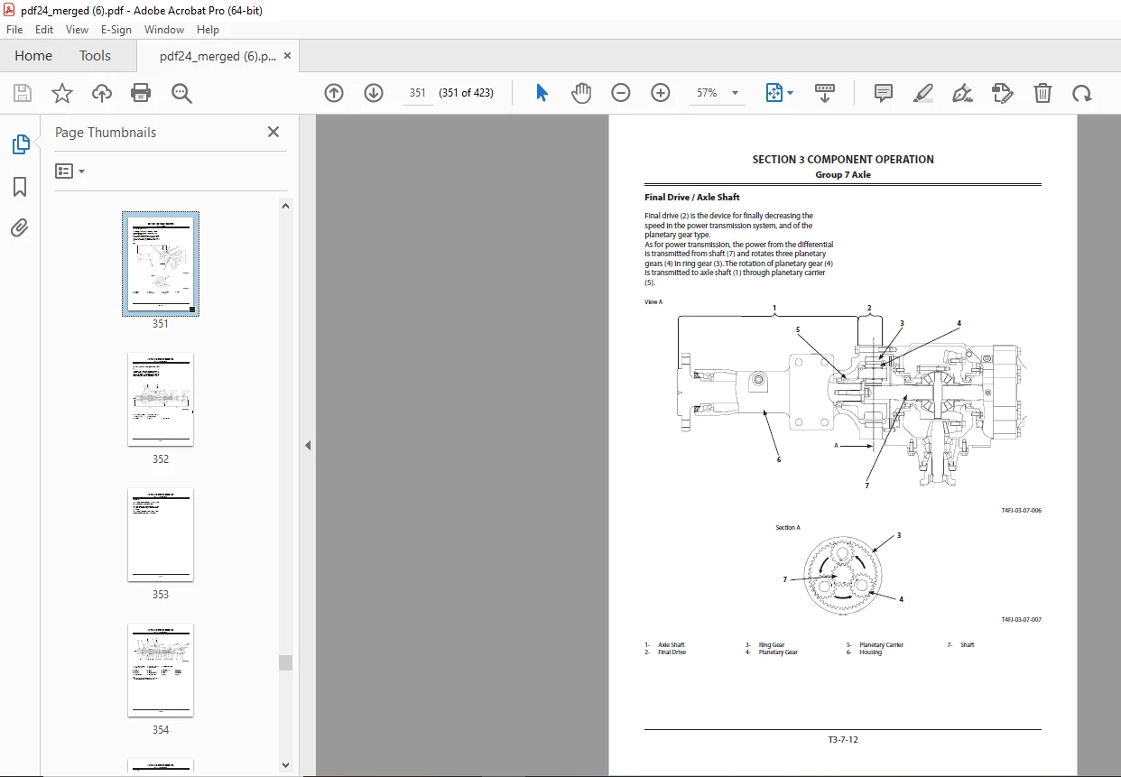
Travel Device349
Outline of Travel Device349
Outline of Travel Reduction Gear350
Outline of Travel Motor351
Operation of Travel Motor351
Outline of Parking Brake352
Operation of Parking Brake (When Parking Brake is Released)353
Operation of Parking Brake (When Parking Brake is Applied)354
Outline of Travel Brake Valve355
Operation of Counterbalance Valve (During Travel)356
Operation of Counterbalance Valve (When Descending a Slope)357
Outline of Travel Relief Valve359
Operation of Travel Relief Valve (During Relief)359
Operation of Travel Relief Valve (During Make-Up)359
Outline of Travel Mode Control361
Operation of Selecting Travel Mode (Slow Speed)361
Operation of Selecting Travel Mode (Fast Speed)361
Signal Control Valve363
Outline of Signal Control Valve363
Pilot Valve Side of Pilot Port363
Control Valve Side of Pilot Port364
Outline of Shuttle Valve365
Outline of Shockless Valve368
Operation of Shockless Valve (During Boom Raise Operation)368
Operation of Shockless Valve (During Boom Lower Operation or When Stopping Boom Raise Operation (Shock Reducing Operation))369
Operation of Flow Combiner Valve Control Spool371
Operation of Swing Parking Brake Release Spool372
Operation of Arm Flow Rate Control Valve Control Spool372
Others (Upperstructure)373
Outline of Pilot Shut-Off Solenoid Valve373
Pilot Shut-Off Lever: LOCK Position374
Pilot Shut-Off Lever: UNLOCK Position374
Outline of Solenoid Valve375
Outline of 4-Spool Solenoid Valve Unit (Control Valve Side)375
Outline of 4-Spool Solenoid Valve Unit (Hydraulic Oil Tank Side)376
Outline of Proportional Solenoid Valve377
Operation of Proportional Solenoid Valve (When in Neutral)377
Operation of Proportional Solenoid Valve (When Excited)377
Outline of Radiator Fan Motor378
Outline of Radiator Fan Valve378
Relief Operation of Radiator Fan Valve379
Make-Up Operation of Radiator Fan Valve380
Outline of Oil Cooler Fan Motor381
Outline of Oil Cooler Fan Valve381
Outline of ON/OFF Solenoid Valve383
Operation of ON/OFF Solenoid Valve (when in Neutral)383
Operation of ON/OFF Solenoid Valve (When in Operation)383
Outline of Pilot Relief Valve384
Outline of Recirculation Valve385
Outline of Shockless Valve385
Operation of Shockless Valve386
Outline of Accumulator (Pilot Circuit)387
Outline of Distribution Valve388
Operation of Distribution Valve388
Others (Undercarriage)393
Outline of Swing Bearing393
Outline of Center Joint393
Outline of Track Adjuster394
SERVICE MANUAL REVISION REQUEST FORM397
S.M 31/1/25