Hitachi ZX 250LC-7 250LCN-7 Hydraulic Excavator Troubleshooting Technical Manual PNTODFY50 PDF
$32.95
Hitachi ZX 250LC-7 250LCN-7 Hydraulic Excavator Troubleshooting Technical Manual PNTODFY50 – PDF DOWNLOAD
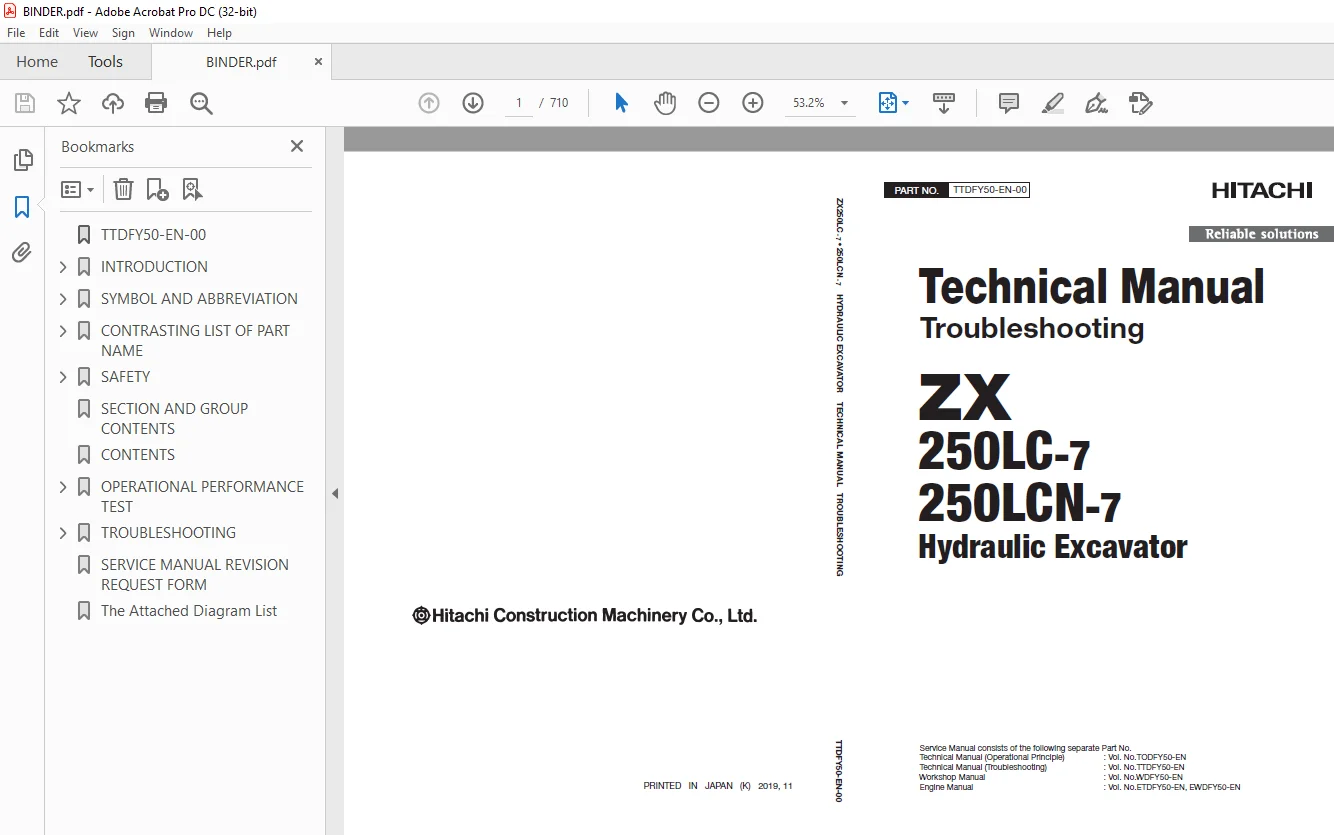
Service Manual consists of the following separate Part No.
Technical Manual (Operational Principle) : Vol. No.TODFY50-EN
Technical Manual (Troubleshooting) : Vol. No.TTDFY50-EN
Workshop Manual : Vol. No.WDFY50-EN
Engine Manual : Vol. No.ETDFY50-EN, EWDFY50-EN
Description
Hitachi ZX 250LC-7 250LCN-7 Hydraulic Excavator Troubleshooting Technical Manual PNTODFY50 – PDF DOWNLOAD
FILE DETAILS:
Hitachi ZX 250LC-7 250LCN-7 Hydraulic Excavator Troubleshooting Technical Manual PNTODFY50 – PDF DOWNLOAD
Language :English
Pages :710
Downloadable : Yes
File Type : PDF
IMAGES PREVIEW OF THE MANUAL:
DESCRIPTION:
Hitachi ZX 250LC-7 250LCN-7 Hydraulic Excavator Troubleshooting Technical Manual PNTODFY50 – PDF DOWNLOAD
Service Manual consists of the following separate Part No.
Technical Manual (Operational Principle) : Vol. No.TODFY50-EN
Technical Manual (Troubleshooting) : Vol. No.TTDFY50-EN
Workshop Manual : Vol. No.WDFY50-EN
Engine Manual : Vol. No.ETDFY50-EN, EWDFY50-EN
To The Reader
This manual is written for an experienced technician to provide technical information needed to maintain and repair this machine.
- The machine specification and description according to destination may be explained on this manual.
- Be sure to thoroughly read this manual for correct product information and service procedures.
- If you have any questions or comments, at if you found any errors regarding the contents of this manual, please
- contact using “Service Manual Revision Request Form” at the end of this manual. (Note: Do not tear off the form. Copy this form for usage.)
Service Material Development Center Hitach Construction Machinery Co., Ltd.
TABLE OF CONTENTS:
Hitachi ZX 250LC-7 250LCN-7 Hydraulic Excavator Operational Technical Manual PN:TODFY50 – PDF DOWNLOAD
Service Manual consists of the following separate Part No.
Technical Manual (Operational Principle) : Vol. No.TODFY50-EN
Technical Manual (Troubleshooting) : Vol. No.TTDFY50-EN
Workshop Manual : Vol. No.WDFY50-EN
Engine Manual : Vol. No.ETDFY50-EN, EWDFY50-EN
TTDFY50-EN-00 1
INTRODUCTION 3
To The Reader 3
Additional References 3
Manual Composition 3
Page Number 3
Trademark 4
Safety Alert Symbol and Headline Notations 4
Units Used 4
SYMBOL AND ABBREVIATION 7
Symbol and Abbreviation 7
CONTRASTING LIST OF PART NAME 9
Contrasting List of Part Name between Technical Manual and Parts Catalog 9
SAFETY 11
Recognize Safety Information 11
Understand Signal Words 11
Follow Safety Instructions 12
Prepare for Emergencies 13
Wear Protective Clothing 13
Protect Against Noise 14
Inspect Machine 14
General Precautions for the Cab 15
Use Handrail and Steps 15
Adjust the Operator’s Seat 16
Ensure Safety Before Rising from or Leaving Operator’s Seat 16
Fasten Your Seat Belt 16
Move and Operate Machine Safely 17
Start the Engine Only from Operator’s Seat 17
Jump Starting 18
Keep Riders off Machine 18
Precautions for Operations 19
Perform Job Site Risk Assessment Beforehand 20
Install OPG Guard 21
Restriction of Attachment Installation 21
Provide Signals for Jobs Involving Multiple Machines 21
Confirm Direction of Machine Travel 22
Drive Machine Safely 23
Avoid Injury from Rollaway Accidents 25
Avoid Accidents from Reversing and Swing Operation 26
Keep People Clear from Working Area 27
Never Position the Bucket Over Anyone 27
Avoid Undercutting 28
Avoid Tipping 28
Never Undercut a High Bank 29
Dig with Caution 29
Caution with an Overhead Obstacle 30
Avoid Power Lines 30
Precautions for Lightning 31
Object Handling 31
Protect Against Flying Debris 32
Park Machine Safely 33
Handle Fluids Safely−Avoid Fires 34
Transport Safely 35
Practice Maintenance Safely 36
Warn Others of Service Work 37
Support Machine Properly 38
Stay Clear of Moving Parts 38
Prevent Parts from Flying 39
Avoid Injury from Attachment Falling Accident 39
Prevent Burns 40
Replace Rubber Hoses Periodically 41
Avoid High-Pressure Fluids 41
Prevent Fires 42
Check for Oil Leaks: 42
Check for Short circuits: 42
Clean up Flammable Materials: 43
Check Key Switch: 43
Check Heat Shields: 43
Evacuating in Case of Fire 44
Beware of Exhaust Fumes 44
Precautions for Welding and Grinding 45
Avoid Heating Near Pressurized Fluid Lines 45
Avoid Applying Heat to Lines Containing Flammable Fluids 45
Precautions for Handling Accumulator and Gas Damper 46
Remove Paint Before Welding or Heating 46
Beware of Asbestos and Silica Dust and Other Contamination 46
Prevent Battery Explosions 47
Service Air Conditioning System Safely 47
Handle Chemical Products Safely 48
Dispose of Waste Properly 48
Never Ride Attachment 49
Notes on Aftertreatment Device 49
Precautions for Communication Terminal 49
Precautions for Communication Terminal Equipment 50
Notes on Protection by Operator’s Station when the Machine Rolls Over 51
Before Returning the Machine to the Customer 51
SECTION AND GROUP CONTENTS 53
CONTENTS 55
OPERATIONAL PERFORMANCE TEST 67
Introduction 69
Operational Performance Tests 69
Preparation for Performance Tests 70
Standard 73
Operational Performance Standard Table 73
Engine System Performance Standards 73
Travel System Performance Standards 74
Swing System Performance Standards 75
Front Attachment System Performance Standards 75
Lever System Performance Standards 79
Combined Operation System Performance Standards 79
Component System Performance Standards 79
Main Pump P-Q Diagram (P1, P2) 80
Main Pump P-Q Diagram (P3) 82
Engine Control Dial Activating Range 84
Pilot Pressure Sensor (4436535) Activating Range 84
Pump Control Pressure Sensor (4436536) Activating Range 85
Pump Delivery Pressure Sensor (4436271) Activating Range 86
Monitor Indicating Values of ECM 87
Monitor Indicating Values of MC 89
Monitor Indicating Values of MC (Pressure Sensor) 92
Monitor Indicating Values of MC (Solenoid Valve) 95
Monitor Indicating Values of Switch Box Controller 96
Engine Test 97
Engine Speed 97
Lubricant Consumption 99
Machine Performance Test 101
Travel Speed 101
Track Link Revolution Speed 101
Mistrack Check 102
Travel Parking Leakage 103
Swing Speed 104
Swing Function Drift Check 105
Swing Motor Leakage 107
Maximum Swingable Slant Angle 108
Swing Bearing Play 109
Hydraulic Cylinder Cycle Time 111
Dig Function Drift Check (Maximum Reach Position) 112
Dig Function Drift Check (Arm Roll-In Position) 114
Control Lever Operating Force 115
Control Lever Stroke 116
Combined Operation of Boom Raise and Swing Function Check 116
Combined Operation of Boom Raise and Arm Roll-In Function Check 118
Clearance of Front Attachment Connecting Part 119
Component Test 121
Primary Pilot Pressure 121
Secondary Pilot Pressure 122
5-Spool Solenoid Valve Unit Set Pressure 123
3-Spool Solenoid Valve Unit Set Pressure 126
2-Spool Solenoid Valve Unit (Aftertreatment Device Regeneration Control) Set Pressure 128
Main Pump Delivery Pressure 131
Main Relief Set Pressure 132
Main Relief Valve Pressure Adjustment Procedure 133
High-Pressure Side of Main Relief Pressure Adjustment Procedure 134
Low-Pressure Side of Main Relief Pressure Adjustment Procedure 136
Relief Pressure (When Relieving Swing) 137
Overload Relief Valve Set Pressure 138
Overload Relief Valve Pressure Adjustment Procedure (Reference) 139
Main Pump Flow Rate Measurement (P-Q Control (Torque Control)) 140
Main Pump Flow Rate Measurement (Pilot Pressure Characteristics) 142
Regulator Adjustment (P1, P2) 146
Regulator Adjustment (P3) 148
Swing Motor Drainage 149
Travel Motor Drainage 152
Adjustment 155
Rewrite of Aftertreatment Device Serial No 155
How to Clear Fault Code 155
Measuring Method of No-Load-Max Differential Pressure 157
Differential Pressure Sensor Learning 158
Filter Maintenance 159
Procedure after Replacing DCU and ECM 159
Air Bleeding from the Diesel Exhaust Fluid Defrosting Piping 160
How to Check Manual Regeneration Switch 162
Remedy at DEF Pressure Decrease 163
Clean DEF Tank 165
Remedy when Mixing Oil in DEF Tank 167
Calibration of Aerial Angle 167
Oil Monitoring Sensor Setting 175
[A] Constant Change (Oil Monitoring Sensor Setting) 176
[D] Sensor Collective Diagnosis (Oil Monitoring Sensor Functional Check) 179
[B] Diagnosis of Engine Oil Monitoring Sensor (Oil Monitoring Sensor Functional Check) 182
[C] Diagnosis of Hydraulic Oil Monitoring Sensor (Oil Monitoring Sensor Functional Check) 185
TROUBLESHOOTING 189
Diagnosing Procedure 199
Introduction 199
Diagnosis Procedure 200
Electrical System Inspection 203
Precautions for Inspection and Maintenance 203
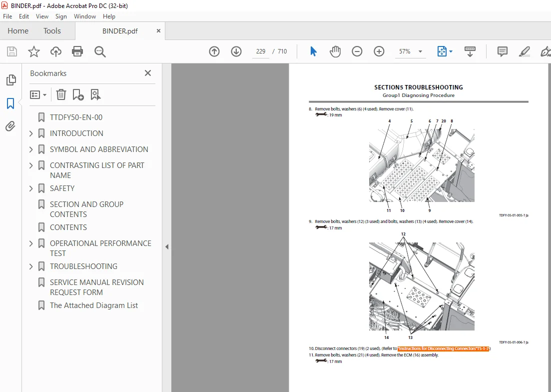
Instructions for Disconnecting Connectors 205
Instructions for Removing Relays 207
Fuse Inspection 208
Fuse Connection Destination 208
Fusible Link Inspection 210
Battery Voltage Check 213
Alternator Check 213
Continuity Check 215
Voltage and Current Measurement of 24-Volt Circuit 216
Voltage and Current Measurement of 5-Volt Circuit 222
Check by False Signal 225
Test Wire Harness 226
Removal of ECM 227
Installation of ECM 230
Removal of DCU 233
Installation of DCU 234
Removal of VGS Controller 236
Installation of VGS Controller 238
Removal of MC (Main Controller) 240
Installation of MC (Main Controller) 242
Removal of Monitor Controller 245
Installation of Monitor Controller 248
Removal of GSM 252
Installation of GSM 255
Removal of PLCU (Option) 259
Installation of PLCU (Option) 262
Removal of Aerial Angle Controller 265
Installation of Aerial Angle Controller 268
Mounting Position of Pump Delivery Pressure Sensor 271
Mounting Position of Pump Control Pressure Sensor 272
Mounting Position of Boom Raise Pilot Pressure Sensor 272
Mounting Position of Arm Roll-Out Pilot Pressure Sensor 273
Mounting Position of Arm 2 Roll-In Pilot Pressure Sensor 273
Mounting Position of Bucket Roll-Out Pilot Pressure Sensor 274
Mounting Position of Bucket Roll-In Pilot Pressure Sensor 274
Mounting Position of Travel Pilot Pressure Sensor 275
Mounting Position of Arm 1 Roll-In Pilot Pressure Sensor 275
Mounting Position of Swing Pilot Pressure Sensor 276
Mounting Position of Front Pilot Pressure Sensor 276
Mounting Position of Auxiliary 1 Pilot Pressure Sensor 277
Mounting Position of Auxiliary 2 Pilot Pressure Sensor 278
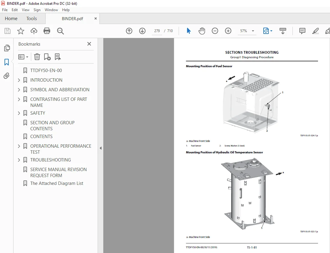
Mounting Position of Fuel Sensor 279
Mounting Position of Hydraulic Oil Temperature Sensor 279
Mounting Position of Differential Pressure Sensor 280
Mounting Position of Exhaust Temperature Sensor 281
Mounting Position of NOx Sensor 282
Mounting Position of Engine Oil Monitoring Sensor 282
Mounting Position of Hydraulic Oil Monitoring Sensor 283
Mounting Position of Ambient Temperature Sensor 284
Mounting Position of Re-circulated Air Temperature Sensor 284
Mounting Position of Frost Sensor 285
Mounting Position of Solar Radiation Sensor 285
Monitor 287
Basic Screen of Monitor 287
Operating Procedures of Service Menu 287
How to Display Service Menu 288
How to Display Troubleshooting Screen 290
How to Display Monitoring 293
Monitoring Items of Engine Controller (ECM) 297
Monitoring Items of Main Controller (MC) 299
Monitoring Items of PLCU 304
Monitoring Items of Monitor Controller (Information) 304
Monitoring Items of Switch Box Controller 305
Monitoring Items of Air Conditioner Unit 306
How to Display Controller Version 306
How to Display Operation 307
How to Display Communication Terminal Status 309
List of Communication Terminal Status 310
Operating Procedures of Breaker Alarm 311
Operating Procedures of Machine Setting (Constant Change) 313
List of Machine Setting Items 316
Operating Procedures of Monitor Setting (Operation Permission) 318
Operating Procedures of Monitor Setting (Maintenance Items) 321
List of Monitor Setting Items 324
Operating Procedures of Attachment Setting (Constant Change) 326
List of Attachment Setting Items 329
Operating Procedures of Engine Setting 332
How to Display Aftertreatment Device No 334
Attachment Adjustment 336
Operating Procedures of Breaker Relief Pressure 336
Operating Procedures of Auxiliary Overload Relief Valve Pressure 340
Inspection of Engine Oil Level and Coolant Level 343
Inspection of Hour Meter and Fuel Gauge 344
Fuel Gauge 345
Coolant Temperature Gauge 346
DEF Gauge 346
Hydraulic Oil Temperature Gauge 347
e-Service 349
Outline of e-Service 349
List of Operation Data 349
Communication System 351
Component Layout 353
Main Component (Upperstructure) 353
Main Component (Undercarriage) 355
Main Component (Front Attachment) 355
Electrical System (Overview) 356
Electrical System (Rear Tray) 357
Electrical System (Switches) 358
Electrical System (Utility Space) 359
Electrical System (Relays) 359
Engine Oil Monitoring Sensor 360
Hydraulic Oil Monitoring Sensor 360
Engine 361
Aftertreatment Device 362
Pump Device 362
Around Pump Device 363
Control Valve 364
Signal Control Valve 364
Swing Device 365
Travel Device 366
5-Spool Solenoid Valve Unit 366
3-Spool Solenoid Valve Unit 367
2-Spool Solenoid Valve Unit (For Aftertreatment Device Regeneration Control) 367
DEF Tank 368
DEF Supply Module 368
Layout of Attachment Spec Parts 369
Around Control Valve 370
Control Valve Lower Side 370
Utility Space 371
Components in Control Valve 372
Pilot Valve Side of Pilot Port 391
Control Valve Side of Pilot Port 393
Port Layout of Control Valve (Main Circuit) 395
Port Layout of Control Valve (Pilot Circuit) 397
Cab Harness 400
Main Harness 411
Pump Harness 420
NOx Harness 421
Monitor Harness 422
Console Harness 423
Control Valve Harness 425
Wiper Harness 427
Wiper Motor Harness 428
Pilot Shut-Off Solenoid Valve Harness 429
Engine Stop Switch Harness 430
Cigar Lighter Sub Harness 431
Radiator Sub Harness 432
Connector Layout of MC 433
Connector Layout of Monitor Controller 434
Connector Layout of ECM and VGS Controller 435
Connector Layout of DCU 436
Connector Layout of GSM 436
Connector Layout of Aerial Angle Controller 437
Connector Layout of PLCU (Option) 437
Troubleshooting A 439
Troubleshooting A (Base Machine Diagnosis by Using Fault Codes) Procedure 439
Contents of Troubleshooting A 439
MC Fault Code 73000-3 440
MC Fault Code 73000-4 442
MC Fault Code 73001-3 444
MC Fault Code 73001-4 445
MC Fault Code 73002-3 445
MC Fault Code 73003-2 446
MC Fault Code 73004-2 446
MC Fault Code 73005-2 446
MC Fault Code 73006-2 447
MC Fault Code 41000-2 447
MC Fault Code 51000-3 448
MC Fault Code 51000-4 449
MC Fault Code 51001-3 450
MC Fault Code 51001-4 451
MC Fault Code 51002-3 451
MC Fault Code 51002-4 452
MC Fault Code 51003-3 453
MC Fault Code 51003-4 454
MC Fault Code 51004-3 454
MC Fault Code 51004-4 455
MC Fault Code 51005-3 456
MC Fault Code 51005-4 457
MC Fault Code 53000-3 457
MC Fault Code 53000-4 458
MC Fault Code 53001-3 459
MC Fault Code 53001-4 460
MC Fault Code 53002-3 460
MC Fault Code 53002-4 461
MC Fault Code 53003-3 462
MC Fault Code 53003-4 463
MC Fault Code 53004-3 464
MC Fault Code 53004-4 465
MC Fault Code 53005-3 465
MC Fault Code 53005-4 466
MC Fault Code 53006-3 467
MC Fault Code 53006-4 468
MC Fault Code 53015-3 468
MC Fault Code 53015-4 469
MC Fault Code 53016-3 470
MC Fault Code 53016-4 471
MC Fault Code 51006-2 471
MC Fault Code 51006-6 472
MC Fault Code 51006-5 473
MC Fault Code 51007-2 473
MC Fault Code 51007-6 474
MC Fault Code 51007-5 475
MC Fault Code 51008-2 475
MC Fault Code 51008-6 476
MC Fault Code 51008-5 477
MC Fault Code 51009-2 477
MC Fault Code 51009-6 478
MC Fault Code 51009-5 479
MC Fault Code 51010-2 479
MC Fault Code 51010-6 480
MC Fault Code 51010-5 480
MC Fault Code 51011-2 481
MC Fault Code 51011-6 482
MC Fault Code 51011-5 482
MC Fault Code 51012-2 483
MC Fault Code 51012-6 484
MC Fault Code 51012-5 484
MC Fault Code 51013-2 485
MC Fault Code 51013-6 486
MC Fault Code 51013-5 486
MC Fault Code 51014-2 487
MC Fault Code 51014-6 488
MC Fault Code 51014-5 488
MC Fault Code 51015-2 489
MC Fault Code 51015-6 489
MC Fault Code 51015-5 490
MC Fault Code 51016-2 491
MC Fault Code 51016-6 491
MC Fault Code 51016-5 492
MC Fault Code 51017-2 493
MC Fault Code 51017-6 493
MC Fault Code 51017-5 494
MC Fault Code 51018-2 494
MC Fault Code 51018-6 495
MC Fault Code 51018-5 495
MC Fault Code 51019-2 495
MC Fault Code 51019-6 496
MC Fault Code 51019-5 497
MC Fault Code 51020-2 497
MC Fault Code 51021-3 498
MC Fault Code 51021-4 499
MC Fault Code 51022-3 500
MC Fault Code 51022-4 500
MC Fault Code 51023-3 501
MC Fault Code 51023-4 502
MC Fault Code 51025-0 502
MC Fault Code 51026-14 503
MC Fault Code 63000-2 503
MC Fault Code 73007-2 503
MC Fault Code 73008-2 504
MC Fault Code 73034-2 504
MC Fault Code 51029-2 504
MC Fault Code 51029-6 505
MC Fault Code 51029-5 506
MC Fault Code 51030-2 506
MC Fault Code 51030-6 507
MC Fault Code 51030-5 508
MC Fault Code 51031-2 508
MC Fault Code 51031-6 509
MC Fault Code 51031-5 510
MC Fault Code 73028-2 510
Monitor Controller (Information) Fault Code 41001-2 511
Monitor Controller (Information) Fault Code 41002-3 511
Monitor Controller (Information) Fault Code 41003-3 512
Monitor Controller (Information) Fault Code 41003-4 513
Monitor Controller (Information) Fault Code 73033-2 514
Monitor Controller (Information) Fault Code 41004-14 515
Monitor Controller (Information) Fault Code 41005-14 515
Monitor Controller (Information) Fault Code 41006-14 516
Monitor Controller (Information) Fault Code 41007-14 516
Monitor Controller (Information) Fault Code 41008-14 516
Monitor Controller (Information) Fault Code 41004-20 517
Monitor Controller (Information) Fault Code 73013-2 517
Monitor Controller (Information) Fault Code 73014-2 518
Monitor Controller (Information) Fault Code 73015-2 518
Monitor Controller (Information) Fault Code 73016-2 518
Monitor Controller (Information) Fault Code 73017-2 519
Monitor Controller (Information) Fault Code 73018-2 519
Monitor Controller (Information) Fault Code 73019-2 520
Monitor Controller (Information) Fault Code 73020-2 520
Monitor Controller (Information) Fault Code 73021-2 521
Monitor Controller (Information) Fault Code 68004-12 521
Monitor Controller (Information) Fault Code 68005-12 521
Monitor Controller (Information) Fault Code 68006-12 521
Monitor Controller (Information) Fault Code 68007-12 522
Monitor Controller (Information) Fault Code 68008-12 522
Monitor Controller (Information) Fault Code 68009-12 522
Monitor Controller (Information) Fault Code 41002-4 522
Monitor Controller (Information) Fault Code 73029-2 523
Monitor Controller (Monitor) Fault Code 73010-2 523
Monitor Controller (Monitor) Fault Code 73011-2 523
Monitor Controller (Monitor) Fault Code 73012-2 524
Monitor Controller (Monitor) Fault Code 73030-2 524
Monitor Controller (Monitor) Fault Code 13911-3 525
Monitor Controller (Monitor) Fault Code 13912-4 525
Monitor Controller (Monitor) Fault Code 13913-3 526
Monitor Controller (Monitor) Fault Code 13914-4 527
Monitor Controller (Monitor) Fault Code 13917-3 527
Monitor Controller (Monitor) Fault Code 13918-4 528
Monitor Controller (Monitor) Fault Code 13921-3 528
Monitor Controller (Monitor) Fault Code 13922-4 529
Monitor Controller (Monitor) Fault Code 13943-2 529
Monitor Controller (Monitor) Fault Code 13944-2 530
Monitor Controller (Monitor) Fault Code 13951-2 531
Monitor Controller (Monitor) Fault Code 13991-2 531
Monitor Controller (Monitor) Fault Code 13992-2 532
Switch Box Controller Fault Code 14504-3 532
Switch Box Controller Fault Code 14504-4 533
Aerial Angle Controller Fault Code 68000-2 533
Aerial Angle Controller Fault Code 68001-2 534
Aerial Angle Controller Fault Code 68002-2 534
Aerial Angle Controller Fault Code 73022-2 535
Aerial Angle Controller Fault Code 68003-2 536
PLCU Fault Code 53007-3 536
PLCU Fault Code 53007-4 537
PLCU Fault Code 53008-3 537
PLCU Fault Code 53008-4 538
PLCU Fault Code 53009-12 539
PLCU Fault Code 53009-7 539
PLCU Fault Code 53010-12 539
PLCU Fault Code 53010-7 540
PLCU Fault Code 53011-2 540
PLCU Fault Code 53011-6 541
PLCU Fault Code 53011-5 541
PLCU Fault Code 53012-2 542
PLCU Fault Code 53012-6 542
PLCU Fault Code 53012-5 543
PLCU Fault Code 53013-2 544
PLCU Fault Code 53013-6 544
PLCU Fault Code 53013-5 545
PLCU Fault Code 53014-2 546
PLCU Fault Code 53014-6 546
PLCU Fault Code 53014-5 547
PLCU Fault Code 53017-2 547
PLCU Fault Code 53018-2 548
PLCU Fault Code 53019-2 548
PLCU Fault Code 53020-2 548
PLCU Fault Code 53021-2 549
PLCU Fault Code 53009-8 549
PLCU Fault Code 53010-8 549
PLCU Fault Code 53017-8 550
PLCU Fault Code 53020-8 550
PLCU Fault Code 53018-8 550
PLCU Fault Code 53021-8 550
PLCU Fault Code 63001-3 551
PLCU Fault Code 63001-4 552
PLCU Fault Code 73023-2 553
PLCU Fault Code 73024-2 553
PLCU Fault Code 73035-7 553
Power-CAN harness Check 554
Body-CAN Harness Check 555
ISO-CAN (Engine) Harness Check 557
IF-CAN Harness Check 559
OPT-CAN Harness Check 560
PL-CAN Harness Check 561
ECM Fault Code List 562
DCU Fault Code List 572
Troubleshooting B 583
Troubleshooting B (Machine Diagnosis by Using Trouble Symptom) Procedure 583
Contents of Troubleshooting B 583
Relationship between Machine Trouble Symptoms and Related Parts 585
When a Fault Occurs in MC (Main Controller) 585
When a Fault Occurs in Switch Box Controller 585
When a Fault Occurs in Engine Control Dial 585
When a Fault Occurs in Auto-Idle Switch 586
When a Fault Occurs in Power Mode Switch (ECO Mode) 586
When a Fault Occurs in Travel Mode Switch 587
When a Fault Occurs in Power Digging Switch 587
When a Fault Occurs in Pilot Shut-Off Switch (Pilot Shut-Off Lever) 587
When a Fault Occurs in Manual Regeneration Switch 588
When a Fault Occurs in Pilot Shut-Off Solenoid Valve 588
When a Fault Occurs in Hydraulic Oil Temperature Sensor 589
When a Fault Occurs in Differential Pressure Sensor 589
When a Fault Occurs in DOC Inlet Exhaust Temperature Sensor 589
When a Fault Occurs in DOC Outlet Exhaust Temperature Sensor 590
When a Fault Occurs in SCR Exhaust Temperature Sensor 590
When a Fault Occurs in Pump 1 Delivery Pressure Sensor 590
When a Fault Occurs in Pump 2 Delivery Pressure Sensor 591
When a Fault Occurs in Pump 3 Delivery Pressure Sensor 591
When a Fault Occurs in Pump 1 Control Pressure Sensor 591
When a Fault Occurs in Pump 2 Control Pressure Sensor 592
When a Fault Occurs in Pump 3 Control Pressure Sensor 592
When a Fault Occurs Swing Pilot Pressure Sensor 592
When a Fault Occurs in Boom Raise Pilot Pressure Sensor 593
When a Fault Occurs in Arm 2 Roll-In Pilot Pressure Sensor 593
When a Fault Occurs in Arm 1 Roll-In Pilot Pressure Sensor 593
When a Fault Occurs in Travel Pilot Pressure Sensor 594
When a Fault Occurs in Front Pilot Pressure Sensor 594
When a Fault Occurs in Bucket Roll-In Pilot Pressure Sensor 594
When a Fault Occurs in Arm Roll-Out Pilot Pressure Sensor 595
When a Fault Occurs in Bucket Roll-Out Pilot Pressure Sensor 595
When a Fault Occurs in Auxiliary 1 Pilot Pressure Sensor (Option) 595
When a Fault Occurs in Auxiliary 2 Pilot Pressure Sensor (Option) 596
When a Fault Occurs in Pump 1 and 2 Torque Control Solenoid Valve 596
When a Fault Occurs in Pump 3 Torque Control Solenoid Valve 597
When a Fault Occurs in Maximum Pump 1 Flow Rate Limit Control Solenoid Valve 597
When a Fault Occurs in Maximum Pump 2 Flow Rate Limit Control Solenoid Valve 597
When a Fault Occurs in Maximum Pump 3 Flow Rate Limit Control Solenoid Valve 598
When a Fault Occurs in 5-Spool Solenoid Valve Unit (SI) 598
When a Fault Occurs in 5-Spool Solenoid Valve Unit (SD) 599
When a Fault Occurs in 5-Spool Solenoid Valve Unit (SE) 599
When a Fault Occurs in 5-Spool Solenoid Valve Unit (SF) 600
When a Fault Occurs in 5-Spool Solenoid Valve Unit (SC) 600
When a Fault Occurs in 3-Spool Solenoid Valve Unit (SK1) 600
When a Fault Occurs in 3-Spool Solenoid Valve Unit (SK2) 601
When a Fault Occurs in 3-Spool Solenoid Valve Unit (SK3) 601
When a Fault Occurs in 2-Spool Solenoid Valve Unit (SZ) 602
When a Fault Occurs in 2-Spool Solenoid Valve Unit (SJ) 602
When a Fault Occurs in Main Relief Valve (For P1, P2) 603
When a Fault Occurs in Main Relief Valve (For P3) 603
When a Fault Occurs in Overload Relief Valve 604
When a Fault Occurs in Boom Anti-Drift Valve 604
When a Fault Occurs in Arm Rod Anti-Drift Valve 604
When a Fault Occurs in Arm Bottom Anti-Drift Valve 605
When a Fault Occurs in Flow Combiner Valve 605
When a Fault Occurs in Boom Regenerative Valve 606
When a Fault Occurs in Arm Regenerative Valve 606
When a Fault Occurs in Bucket Regenerative Valve 606
When a Fault Occurs in Bucket Regeneration Cut Valve 607
When a Fault Occurs in Arm 1 Flow Rate Control Valve 607
When a Fault Occurs in Auxiliary Flow Rate Control Valve 607
When a Fault Occurs in Auxiliary Flow Combiner Valve 608
When a Fault Occurs in Pump 1 Bypass Shut-Out Valve 608
When a Fault Occurs in Pump 3 Bypass Shut-Out Valve 609
When a Fault Occurs in Digging Regenerative Valve 609
When a Fault Occurs in Boom Lower Meter-In Cut Valve 610
When a Fault Occurs in Arm Roll-In Meter-Out Open Control Spool 610
When a Fault Occurs in Travel Motor Displacement Angle Control Valve 611
When a Fault Occurs in Pump 1 Flow Rate Control Valve 611
When a Fault Occurs in Pump 2 Flow Rate Control Valve 612
When a Fault Occurs in Pump 3 Flow Rate Control Valve 612
When a Fault Occurs in Swing Parking Brake Release Spool 613
When a Fault Occurs in Flow Combiner Valve Control Spool 613
When a Fault Occurs in Auxiliary Flow Combiner Control Solenoid Valve (Option) 614
When a Fault Occurs in Auxiliary Flow Rate Control Solenoid Valve (Option) 614
When a Fault Occurs in Selector Valve Control Solenoid Valve (Option) 614
When a Fault Occurs in Selector Valve (Option) 615
When a Fault Occurs in Accumulator Control Valve (Option) 615
When a Fault Occurs in Breaker Relief Solenoid Valve (Option) 615
When a Fault Occurs in Auxiliary Overload Relief Solenoid Valve (Option) 616
Identification Symbol of Troubleshooting B 616
Correlation between Trouble Symptoms and Part Failures 617
Parts Related with “E-1 Starter does not rotate ” 617
Parts Related with “E-2 Even if starter rotates, engine does not start ” 617
Parts Related with “E-3 Even if power mode switch is operated, power mode is not shifted ” 617
Parts Related with “E-4 ECO mode is faulty ” 618
Parts Related with “E-5 Travel HP mode is faulty ” 618
Parts Related with “E-6 Auto-idle system is faulty ” 618
Parts Related with “E-7 Even if pilot shut-off lever is set to UNLOCK position with engine running at slow idle speed, engine speed does not increase ” 619
Parts Related with “E-8 Engine speed does not increase when coolant temperature is low ” 619
Parts Related with “E-9 Auto shut-down is not activated ” 619
Parts Related with “E-12 Engine speed does not decrease when audio mute/one-touch idle switch is pushed ” 620
Parts Related with “A-1 All actuators do not work ” 620
Parts Related with “A-2 All actuator speeds are slow ” 620
Parts Related with “A-3 Actuator does not stop even if control lever is set to neutral ” 621
Parts Related with “A-4 Manual regeneration of aftertreatment device cannot be performed ” 621
Parts Related with “A-5 Travel (right) operation speed is slow when performing travel single operation Bucket single operation speed is slow (All problems occur at the same time )” 622
Parts Related with “A-6 Travel (left) operation speed is slow when performing travel single operation Attachment single operation speed is slow (All problems occur at the same time )” 622
Parts Related with “A-9 Swing single operation speed is slow Boom speed is slightly slow when performing arm level crowding operation (All problems occur at the same time )” 622
Parts Related with “F-1 All front attachment actuator powers are weak ” 622
Parts Related with “F-2 Front attachment drifts remarkably ” 623
Parts Related with “F-3 When boom raise or arm roll-out is operated, boom or arm starts to move after moving slightly down ” 623
Parts Related with “F-4 Even if power digging switch is pushed, power does not increase Boom raise power is weak when performing digging operation ” 623
Parts Related with “F-5 Boom, arm, or bucket single operation is not operated Boom, arm, or bucket single operation speed is slow ” 624
Parts Related with “F-6 Bucket roll-in speed is slow or power is weak when performing digging operation ” 624
Parts Related with “F-7 When performing combined operation, arm does not start to move smoothly Arm starts to move slightly slow when performing arm single operation These troubles often occur when temperature is low ” 625
Parts Related with “F-8 When performing combined operation, boom does not start to move smoothly Boom starts to move slightly slow when performing boom lower single operation ” 625
Parts Related with “F-9 Boom lower speed above ground is faster than other actuators when performing combined operation Machine cannot be raised off the ground ” 625
Parts Related with “F-10 Arm roll-in speed is slow when performing digging operation ” 625
Parts Related with “F-11 Arm roll-in speed is fast when performing arm level crowding operation Arm power is weak when performing digging operation ” 626
Parts Related with “F-12 Arm roll-out speed is slow when performing combined operation of boom raise, arm roll-out, and attachment ” 626
Parts Related with “F-14 Boom raise or attachment speed is slow when performing combined operation of boom raise and arm or attachment and arm ” 627
Parts Related with “F-16 Boom raise speed is slow when performing combined operation of swing and boom raise ” 627
Parts Related with “F-22 Bucket speed is slow when performing combined operation of arm roll-in and bucket Boom raise speed is slow when performing combined operation of swing, boom raise, and arm roll-in Arm roll-in speed is slow ” 628
Parts Related with “F-23 Arm roll-out speed is slow ” 628
Parts Related with “F-24 Arm roll-in speed is slow when performing combined operation of boom raise and arm roll-in ” 628
Parts Related with “S-1 Swing speed is slow or is not operated ” 629
Parts Related with “S-2 When starting swing operation, swing speed is fast ” 629
Parts Related with “T-1 Both of right and left travels are not operated or travel speed is slow ” 630
Parts Related with “T-2 One side travel is not operated or travel speed is slow Machine mistracks ” 630
Parts Related with “T-3 Machine mistracks when performing combined operation of travel and front attachment ” 630
Parts Related with “T-4 Fast travel can not be selected Travel mode does not change from slow speed mode to fast speed mode ” 630
Parts Related with “T-5 Occasionally, machine may mistrack when traveling with engine running at slow speed ” 631
Parts Related with “T-6 Attachment speed is slow when performing attachment single operation Travel speed is slow when performing combined operation of attachment and travel ” 631
Parts Related with “O-1 Work light does not light ” 632
Parts Related with “O-2 Cab light does not light ” 632
Parts Related with “O-3 Wiper is not operated ” 632
Parts Related with “O-4 Washer is not operated ” 632
Parts Related with “O-5 Boom light does not light ” 633
E-1 Starter does not rotate 633
E-2 Even if starter rotates, engine does not start 634
E-3 Even if power mode switch is operated, power mode is not shifted 635
E-4 ECO mode is faulty 635
E-5 Travel HP mode is faulty 636
E-6 Auto-idle system is faulty 636
E-7 Even if pilot shut-off lever is set to UNLOCK position with engine running at slow idle speed, engine speed does not increase 637
E-8 Engine speed does not increase when coolant temperature is low 637
E-9 Auto shut-down is not activated 637
E-12 Engine speed does not decrease when audio mute/one-touch idle switch is pushed 638
A-1 All actuators do not work 639
A-2 All actuator speed are slow 640
A-3 Actuator does not stop even if control lever is set to neutral 641
A-4 Manual regeneration of aftertreatment device cannot be performed 641
A-5 Travel (right) operation speed is slow when performing travel single operation Bucket single operation speed is slow (All problems occur at the same time ) 642
A-6 Travel (left) operation speed is slow when performing travel single operation Attachment single operation speed is slow (All problems occur at the same time ) 642
A-9 Swing single operation speed is slow Boom speed is slightly slow when performing arm level crowding operation (All problems occur at the same time ) 643
F-1 All front attachment actuator powers are weak 643
F-2 Front attachment drifts remarkably 644
F-3 When boom raise or arm roll-out is operated, boom or arm starts to move after moving slightly down 645
F-4 Even if power digging switch is pushed, power does not increase Boom raise power is weak when performing digging operation 645
F-5 Boom, arm, or bucket single operation is not operated Boom, arm, or bucket single operation speed is slow 646
F-6 Bucket roll-in speed is slow or power is weak when performing digging operation 647
F-7 When performing combined operation, arm does not start to move smoothly Arm starts to move slightly slow when performing arm single operation These troubles often occur when temperature is low 647
F-8 When performing combined operation, boom does not start to move smoothly Boom starts to move slightly slow when performing boom lower single operation 647
F-9 Boom lower speed above ground is faster than other actuators when performing combined operation Machine cannot be raised off the ground 648
F-10 Arm roll-in speed is slow when performing digging operation 648
F-11 Arm roll-in speed is fast when performing arm level crowding operation Arm power is weak when performing digging operation 649
F-12 Arm roll-out speed is slow when performing combined operation of boom raise, arm roll-out, and attachment 649
F-14 Boom raise or attachment speed is slow when performing combined operation of boom raise and arm or attachment and arm 649
F-16 Boom raise speed is slow when performing combined operation of swing and boom raise 650
F-22 Bucket speed is slow when performing combined operation of arm roll-in and bucket Boom raise speed is slow when performing combined operation of swing, boom raise, and arm roll-in Arm roll-in speed is slow 650
F-23 Arm roll-out speed is slow 650
F-24 Arm roll-in speed is slow when performing combined operation of boom raise and arm roll-in 651
S-1 Swing speed is slow or is not operated 651
S-2 When starting swing operation, swing speed is fast 652
T-1 Both of right and left travels are not operated or travel speed is slow 652
T-2 One side travel is not operated or travel speed is slow Machine mistracks 653
T-3 Machine mistracks when performing combined operation of travel and front attachment 654
T-4 Fast travel can not be selected Travel mode does not change from slow speed mode to fast speed mode 654
T-5 Occasionally, machine may mistrack when traveling with engine running at slow speed 655
T-6 Attachment speed is slow when performing attachment single operation Travel speed is slow when performing combined operation of attachment and travel 656
O-1 Work light does not light 656
O-2 Cab light does not light 657
O-3 Wiper is not operated 657
O-4 Washer is not operated 658
O-5 Boom light does not light 659
Exchange Inspection 659
How to Lower Boom in Case of Emergency and When Engine Stops without Hose Rupture Valve 663
How to Lowering Boom When Emergency and When Engine Stops with Hose Rupture Valve 664
Attachment Circuit Pressure Release Procedure 664
Air Conditioner 667
Outline of Air Conditioner 667
Component Layout of Air Conditioner 668
Functions of Main Electrical Parts 670
Troubleshooting of Air Conditioner 673
Monitor Controller (Monitor) Fault Code 13911-3 674
Monitor Controller (Monitor) Fault Code 13912-4 674
Monitor Controller (Monitor) Fault Code 13913-3 675
Monitor Controller (Monitor) Fault Code 13914-4 676
Monitor Controller (Monitor) Fault Code 13917-3 676
Monitor Controller (Monitor) Fault Code 13918-4 677
Monitor Controller (Monitor) Fault Code 13921-3 677
Monitor Controller (Monitor) Fault Code 13922-4 678
Monitor Controller (Monitor) Fault Code 13943-2 678
Monitor Controller (Monitor) Fault Code 13944-2 679
Monitor Controller (Monitor) Fault Code 13951-2 680
Monitor Controller (Monitor) Fault Code 13991-2 680
Monitor Controller (Monitor) Fault Code 13992-2 681
Faulty Cooling (1) 682
Faulty Cooling (2) 683
Faulty Cooling (3) 684
Faulty Cooling (4) 686
Faulty Cooling (5) 687
Faulty Heating (1) 689
Faulty Heating (2) 690
Others 690
Blower motor does not operate 691
Compressor clutch does not operate 692
Cooling Circuit Check by Using Manifold Gauge 694
Work after Replacing Components 697
Refill compressor oil 698
Necessity of Purging 698
Procedures for Charging Air Conditioner with Refrigerant 700
Warm-Up Operation 705
Hose and Pipe Tightening Torque 707
SERVICE MANUAL REVISION REQUEST FORM 709
The Attached Diagram List 710
S.M 6/2/2025