

Hitachi Hydraulic Excavator UH043 Service Manual – PDF DOWNLOAD
FILE DETAILS:
Hitachi Hydraulic Excavator UH043 Service Manual – PDF DOWNLOAD
Language : English
Pages :425
Downloadable : Yes
File Type : PDF
Size:21.1 MB
IMAGES PREVIEW OF THE MANUAL:
DESCRIPTION
Hitachi Hydraulic Excavator UH043 Service Manual – PDF DOWNLOAD
FOREWORD
- This service manual explains the correct maintenance and repair procedures to ensure optimal performance and maximum service life for Hitachi construction machinery.
- Tne serviceman is requested to read the manual thoroughly and consult it whenever he is not sure of correct servicing. Use the manual not only as a reference guide to maintenance but also a textbook to train new serviceiren who are lillfamiliar with Hitachi construction machinery.
- The manual is divided into four sections such as SPECIFICATIONS, OPERATIONAL PRINCIPLE, DISASSEMBLY and ASSEMBLY and MAINTENANCE STANDARD. A thorough knowledge of the these will help to:
- Diagnose the cause of the failure.
- Determine reuse or replacement of parts.
- 3. Install the units and assemble the parts correctly. We hope that this manual will aid in quick, easy and lower cost servicing of the machines.
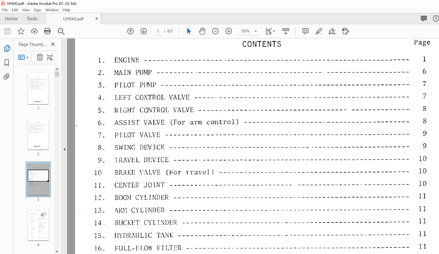
TABLE OF CONTENTS:
Hitachi Hydraulic Excavator UH043 Service Manual – PDF DOWNLOAD
UH043 SERVICEMANUAL……………………………………………. 1
FORWORD…………………………………………………… 1
CARE OF THE HANDLING……………………………………….. 2
SECTION 01 SPECIFICATIONS…………………………………… 3
Group 01 Specifications ………………………………… 4
Engine ……………………………………………. 4
Main Pump …………………………………………. 9
Pilot Pump ………………………………………… 10
Cntrol Valve (Left)…………………………………. 10
Cntrol Valve (Right)………………………………… 11
Assist Valve……………………………………….. 11
Pilot Valve………………………………………… 12
Swing Device……………………………………….. 12
Travel Device………………………………………. 13
Brake Valve (for Travel)…………………………….. 13
Center Joint……………………………………….. 13
Boom Cylinder………………………………………. 14
Arm Cylinder……………………………………….. 14
Bucket Cylinder…………………………………….. 14
Hydraulic Tank……………………………………… 14
Full-Flow Filter……………………………………. 14
Suction Filter……………………………………… 14
Oil Cooler…………………………………………. 14
Relief Valve ……………………………………… 15
Slow Return Valve …………………………………. 15
Check Valve (for Right Travel and Arm II Control Valve)…. 15
Check Valve (with Orifice)…………………………… 15
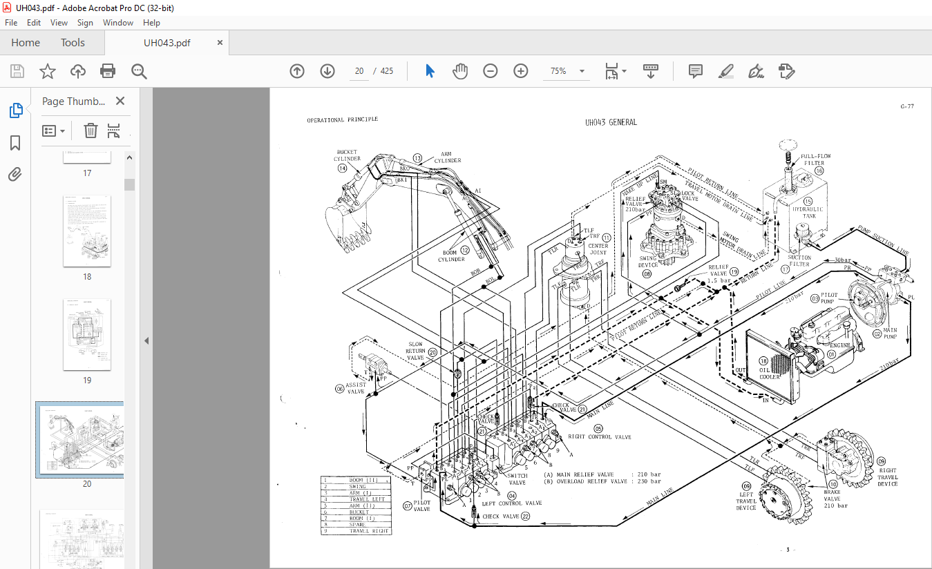
SECTION 02 OPERATIONAL PRINCIPLE…………………………….. 16
Group 01 General ………………………………………. 17
Hydraulic System …………………………………… 18
Construction……………………………………. 18
Hydraulic Circuit……………………………….. 19
Main Hydraulic Circuit……………………….. 23
Pilot Circuit……………………………….. 25
Single Operation………………………………… 27
Boom Operation………………………………. 27
Arm Operation……………………………….. 31
Arm Slow-Return Valve Function………………… 35
Overlord Relief Valve Function………………… 36
Bucket Operation…………………………….. 37
Swing Operation……………………………… 39
Travel Operation…………………………….. 43
Combined Operation………………………………. 49
Swing and Travel Operation……………………. 50
Arm and Travel Operation……………………… 51
Boom and Travel Operation…………………….. 52
Swing and Arm Operation………………………. 53
Superstructure……………………………………… 54
Outline………………………………………… 54
Control Levers………………………………….. 55
Undercarrige……………………………………….. 60
Outline ……………………………………….. 60
Track Spring and Adjuster………………………… 61
Swing Bearing…………………………………… 63
Electric System…………………………………….. 65
General………………………………………… 65
Monitoring and Alarming System……………………. 68
Group 02 Assist Valve…………………………………… 81
Group 03 HVBC 04 Brake Valve (for Travel)…………………. 85
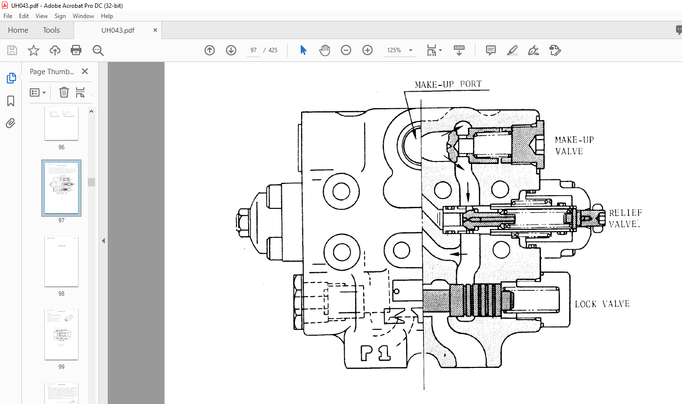
Group 04 VLCR-07SG-S Lock Valve (for Swing)……………….. 93
Group 05 Slow Return Valve………………………………. 98
Group 06 CV-20 Control Valve……………………………..101
Group 07 Cylinder……………………………………….112
Group 08 Full-Flow Filter………………………………..115
Group 09 HMFC Motor (for Travel)………………………….118
Group 10 MSF 175 Swing Motor……………………………..122
Group 11 Monitor Troubleshooting………………………….127
Introduction………………………………………..128
Meter(s) does not Work……………………………….130
Maloperation of Hourmeter…………………………….130
Maloperation of Water Temperature gauge………………..131
Accuracy Check of Water Temperature gauge………………132
Maloperation of Fuel Gauge……………………………133
Accuracy Check of Fuel Gauge………………………….134
Monitor Lamp………………………………………..135
Maloperation of Battery Charge Warning Lamp…………….136
Maloperation of Engine Oil Pressure Warning Lamp………..137
Maloperation of Engine Overheat Warning Lamp……………138
Maloperation of Air Cleaner Clog Warning Lamp…………..139
Maloperation of Headlight Pilot Lamp ………………….140
Buzzer I……………………………………………141
Buzzer II…………………………………………..142
Circuit Diagram……………………………………..143
Group 12 Reduction Device (for Swing)……………………..145
Group 13 Pump A8V55 ER-1…………………………………148
Pump A8V55………………………………………….149
Outline ………………………………………..149
Construction…………………………………….150
Operation……………………………………….152
Variable Displacement…………………………….156
Regulator ER-1………………………………………157
Outline ………………………………………..157
Operational Principle…………………………….160
Constant output Control……………………….161
Summation System……………………………..167
Group 14 Traction Device…………………………………171
SECTION 03 DISASSEMBLY AND ASSEMBLY…………………………..175
Group 01 Assist Valve……………………………………176
Group 02 HVBC 04 Brake Valve (for Travel)………………….183
Group 03 VLCR-07SG-S Lock Valve (for Swing)………………..195
Necessary Tools……………………………………..196
Disassembling Instructions……………………………197
Maintenance Standerd…………………………………200
Assembling Instruction……………………………….202
Valve Performance……………………………………205
Troubleshooting……………………………………..206
Group 04 CV-20 Control Valve……………………………..213
Disassembly ………………………………………..214
Control Valve……………………………………….214
Overlod Relief Valve…………………………………218
Main Relief Valve……………………………………220
Switch Valve………………………………………..222
Inspection………………………………………….224
Assembly …………………………………………..225
Switch Valve………………………………………..225
Main Relief Valve……………………………………226
Overload Relief Valve………………………………..229
Control Valve……………………………………….232
Troubleshooting……………………………………..240
Group 05 Cylinder……………………………………….243
Group 06 Front Idler…………………………………….251
Group 07 HMFC Motor (for Travel)………………………….257
Group 08 MSF 175 Swing Motor……………………………..274
Necessary Tools……………………………………..275
Disassembly ………………………………………..276
Maintenance Standard…………………………………279
Assembly……………………………………………280
Troubleshooting……………………………………..284
Group 09 Lower Roller……………………………………289
Group 10 Reduction Device (for Swing)……………………..294
Group 11 A8V55 ER-1……………………………………..303
Disassembly ………………………………………..304
Main Conpornents…………………………………305
Regulator……………………………………….307
Regulator Cover………………………………….311
Gear Pump……………………………………….312
Pilot Control Valve………………………………313
Relief Valve…………………………………….314
Assembly……………………………………………317
Pilot Control Valve………………………………318
Gear Pump……………………………………….320
Relief Valve…………………………………….322
Regulator Cover………………………………….324
Regulator……………………………………….326
Main Compornents…………………………………331
Group 12 Swing Device……………………………………341
Group 13 Traction Device…………………………………346
Group 14 Upper Roller……………………………………365
SECTION 04 MAINTENANCE STANDERD………………………………371
General………………………………………………..372
Maintenance Standard…………………………………….374
Swing Bearing ………………………………………374
Spprocket…………………………………………..375
Front Idler…………………………………………376
Track Link Tension Adjustment…………………………377
Lower Roller and Upper Rooler…………………………379
Track Link and Shoe………………………………….381
Front-End Attachment…………………………………385
Perfomance Standerd……………………………………..387
Check of Amount of Oil……………………………….387
Travel Performance Standard…………………………..389
Swing Performance Standard……………………………394
Performance Standard of Front-End Attchment…………….397
Performance Standard of Control Levers…………………400
Hydraulic Units Standard…………………………………403
Pump A8V55 ER-1……………………………………..403
Main Control Valve Relief Set Pressure…………………414
Overlord Relief Valve Set Pressure ……………………417
Travel Motor………………………………………..418
Travel Motor Brake Valve Test…………………………420
Swing Motor…………………………………………422
Swing Motor Relief Valve Test…………………………424
VIDEO PREVIEW OF THE MANUAL:
PLEASE NOTE:
- This is the SAME manual used by the dealers to troubleshoot any faults in your vehicle. This can be yours in 2 minutes after the payment is made.
- Contact us at [email protected] should you have any queries before your purchase or that you need any other service / repair / parts operators manual.
S.M


