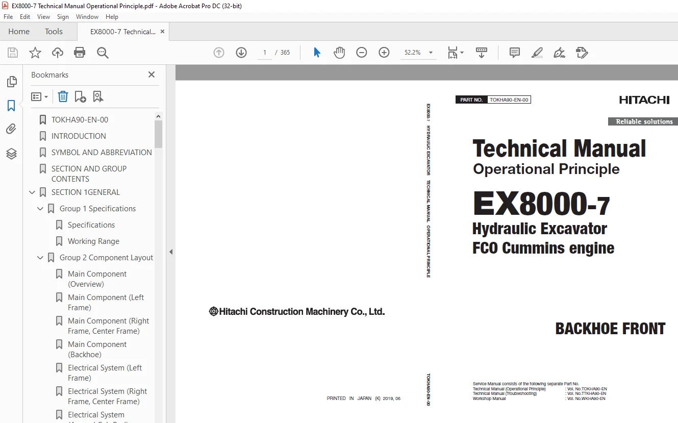
Hitachi EX8000-7 Hydraulic Excavator FCO Cummins engine Operational Technical Manual PNTOKHA90
$29.95
Hitachi EX8000-7 Hydraulic Excavator FCO Cummins engine Operational Technical Manual PNTOKHA90 – PDF DOWNLOAD
Service Manual consists of the following separate Part No.
Technical Manual (Operational Principle) : Vol. No.TOKHA90-EN
Technical Manual (Troubleshooting) : Vol. No.TTKHA90-EN
Workshop Manual : Vol. No.WKHA90-EN
Description
Hitachi EX8000-7 Hydraulic Excavator FCO Cummins engine Operational Technical Manual PNTOKHA90 – PDF DOWNLOAD
FILE DETAILS:
Hitachi EX8000-7 Hydraulic Excavator FCO Cummins engine Operational Technical Manual PNTOKHA90 – PDF DOWNLOAD
Language :English
Pages :365
Downloadable : Yes
File Type : PDF
IMAGES PREVIEW OF THE MANUAL:
DESCRIPRION:
Hitachi EX8000-7 Hydraulic Excavator FCO Cummins engine Operational Technical Manual PNTOKHA90 – PDF DOWNLOAD
- This manual is written for an experienced technician to provide technical information needed to maintain and repair this machine. The machine specification and description according to destination may be explained on this manual.
- Be sure to thoroughly read this manual for correct product information and service procedures
- If you have any questions or comments, at if you found any errors regarding the contents of this manual, please contact using “Service Manual Revision Request Form” at the end of this manual. (Note: Do not tear off the form. Copy it for usage.)
Hitachi EX8000-7 Hydraulic Excavator FCO Cummins engine Operational Technical Manual PNTOKHA90 – PDF DOWNLOAD
TOKHA90-EN-00 1
INTRODUCTION 3
SYMBOL AND ABBREVIATION 5
SECTION AND GROUP CONTENTS 7
SECTION 1GENERAL 9
Group 1 Specifications 11
Specifications 11
Working Range 12
Group 2 Component Layout 15
Main Component (Overview) 15
Main Component (Left Frame) 16
Main Component (Right Frame, Center Frame) 17
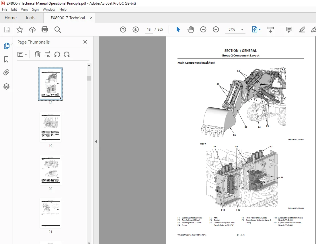
Main Component (Backhoe) 18
Electrical System (Left Frame) 19
Electrical System (Right Frame, Center Frame) 20
Electrical System (Around Cab Bed) 21
Electrical System (In Cab) 22
Electrical System (Isolation Switch Box) 25
Electrical System (Relay Box) 26
Electrical System (Electrical Equipment Box) 27
Electrical System (Relay Layout of Electrical Equipment Box) 28
Electrical System (LED Layout of Contamination Sensor Amplifier) 29
Electrical System (Monitoring Controller Box) 30
Electrical System (Left Pump Compartment Controller Box) 31
Electrical System (Right Pump Compartment Controller Box) 32
Electrical System (Angle Sensor) 33
Left Engine 34
Left Intake Exhaust Unit 35
Around Left Radiator 36
Left Water Tank 37
Around Left Pump 38
Left Air Fan 40
Folding Stairway 41
Right Engine 44
Right Intake Exhaust Unit 45
Around Right Radiator 46
Right Water Tank 47
Around Right Pump 48
Right Air Fan 50
Around Oil Cooler 51
Auto-Lubrication Device 52
Control Valve (Center Pilot Panel) 53
Center Pilot Panel 58
EDQR Valve (Center Pilot Panel) 59
Fuel Cooler, Transmission Oil Cooler 60
Around Hydraulic Oil Tank 61
Fuel Tank 62
Fast-Filling System 63
Swing Device 64
Center Joint 65
Travel Device 66
Undercarriage 67
Control Valve (Front Pilot Panel) 68
EDQR Valve (Front Pilot Panel) 69
3-Spool Solenoid Valve Unit 70
Layout of Fuse 71
Group 3 Component Specifications 79
Engine 79
Heat Exchanger 83
Battery 84
Hydraulic Component 85
Electrical Component 89
SECTION 2SYSTEM 95
Group 1 Controller 97
Outline 97
MCU: Monitor Control Unit (Alarm Monitor and Sub-Control System Control Unit)102
ELUF: Electric Lever Control Unit for Front (Electric Control Lever Controller (for Controlling Front Attachment Operation))108
ELUT: Electric Lever Control Unit for Travel (Electric Control Lever Controller (for Controlling Travel Operation))112
ELUV: Electric Lever Control Unit for Front Valve (Electric Control Lever Controller (for Controlling Front Valve Operation))116
PFU: Pump Flow Control Unit (Pump Flow Rate Control Controller)118
IDU: Information Display Unit (Information Display Controller)121
ECM: Engine Control Module (Engine Controller)128
DLU: Data Logging Unit130
CSU: Contamination Sensing Unit132
HMU: Hydraulic System Monitoring Unit134
PMU: Pump Monitoring Unit136
EHU: Engine Heat Balance Monitoring Unit (Engine Cooling System Monitoring Unit)138
ODR: Operation Data Recorder140
BPU: Basic Performance Monitoring Unit142
Group 2 Control System145
Outline145
Engine Control147
Pump Control154
Sub-Control System Control168
Fast-Filling Panel Lower Control170
Other Controls184
Travel Mode Control188
Cab Bed Pressurization Control192
Group 3 ELU System197
Outline197
Pilot Shut-Off Control198
Boom Lower Flow Rate Regeneration Control200
Cylinder Stroke End Shock Prevention Control202
Adjuster Cylinder End Travel Limitation Control204
Swing Stop Control206
Group 4 Hydraulic System209
Outline209
Pilot Circuit210
Main Circuit214
Other Actuator Circuits224
Travel Shock Absorbing/Travel Stop Circuit226
Group 5 Electrical System227
Outline227
Main Circuit228
Electric Power Circuit (Key Switch: OFF)230
Electric Power Circuit (Key Switch: ACC)232
Electric Power Circuit (Key Switch: ON)234
Engine Starting Circuit (Engine Start Switch: ON)246
Charging Circuit (Key Switch: ON-Engine: Running)250
Engine Stop Circuit252
Surge Voltage Prevention Circuit258
Group 6 Air Conditioning System261
Outline261
Functions of Main Components262
Functions of Main Electrical Parts263
SECTION 3COMPONENT OPERATION269
Group 1 Pump Device271
Outline271
Main Pump272
Radiator Fan Motor Pump, Oil Cooler Fan Motor Pump274
Regulator for Main Pump275
Regulator for Radiator Fan Motor Pump, Regulator for Oil Cooler Fan Motor Pump283
Pump Control Solenoid Valve298
Gear Pump300
Pump Delivery Pressure Sensor300
Regulator Pressure (Flow Rate Control Pressure) Sensor300
Contamination Sensor301
Group 2 Swing Device303
Outline303
Swing Motor304
Swing Parking Brake306
Swing Reduction Gear307
Valve Unit308
Group 3 Control Valve311
Overview311
Operational Principle312
Main Relief Valve315
Overload Relief Valve315
Make-Up Valve316
Group 4 Control Equipment317
Outline317
Electric Control Lever318
EDQR Valve for Electric Control Lever322
Group 5 Travel Device327
Outline327
Travel Motor328
Travel Mode Control330
Brake Valve334
Parking Brake336
Travel Reduction Gear337
Group 6 Others (Upperstructure)339
Oil Cooler Fan Motor339
Air Conditioner Compressor Motor, Radiator Fan Motor, Air Fan Motor, Fuel Cooler/Pump Transmission Oil Cooler Fan Motor341
Folding Stairway Pump Unit343
Pilot Relief Valve344
Fan Valve345
Solenoid Valve351
Reducing Valve for Travel Mode Control352
Accumulator353
Group 7 Others (Undercarriage)355
Swing Bearing355
Accumulator356
Adjuster Cylinder357
Center Joint358
Group 8 Others (Front Attachment)359
Make-Up Valve359
3-Spool Solenoid Valve Unit362
SERVICE MANUAL REVISION REQUEST FORM365
S.M 31/1/25