Hitachi EX5600-7B Hydraulic Excavator Tier 4 Final Cummins engine Workshop Manual PN: WKGB91 PDF
$38.95
Hitachi EX5600-7B Hydraulic Excavator Tier 4 Final Cummins engine Workshop Manual PN: WKGB91 – PDF DOWNLOAD
Service Manual consists of the following separate Part No.
Technical Manual (Operational Principle) : Vol. No.TOKGB91-EN
Technical Manual (Troubleshooting) : Vol. No.TTKGB91-EN
Workshop Manual : Vol. No.WKGB91-EN
Description
Hitachi EX5600-7B Hydraulic Excavator Tier 4 Final Cummins engine Workshop Manual PN: WKGB91 – PDF DOWNLOAD
FILE DETAILS:
Hitachi EX5600-7B Hydraulic Excavator Tier 4 Final Cummins engine Workshop Manual PN: WKGB91 – PDF DOWNLOAD
Language :English
Pages :1882
Downloadable : Yes
File Type : PDF
IMAGES PREVIEW OF THE MANUAL:’
DESCRIPRION:
Hitachi EX5600-7B Hydraulic Excavator Tier 4 Final Cummins engine Workshop Manual PN: WKGB91 – PDF DOWNLOAD
Service Manual consists of the following separate Part No.
Technical Manual (Operational Principle) : Vol. No.TOKGB91-EN
Technical Manual (Troubleshooting) : Vol. No.TTKGB91-EN
Workshop Manual : Vol. No.WKGB91-EN
- This manual is written for an experienced technician to provide technical information needed to maintain and repair this machine. The machine specification and description according to destination may be explained on this manual.
- Be sure to thoroughly read this manual for correct product information and service procedures
- If you have any questions or comments, at if you found any errors regarding the contents of this manual, please contact using “Service Manual Revision Request Form” at the end of this manual.
Manual Composition
This manual consists the Technical Manual, the Workshop Manual and the Engine Manual.
- Information included in the Technical Manual: Technical information needed for redelivery and delivery, operation and activation of all devices and systems, operational performance tests, and troubleshooting procedures
- Information included in the Workshop Manual: Technical information needed for maintenance and repair of the machine, tools and devices needed for maintenance and repair, maintenance standards, and removal / installation and assemble / disassemble procedures.
- Information included in the Engine Manual: Technical information needed for redelivery and delivery and maintenance and repair of the machine, operation and activation of all devices and systems, troubleshooting and assemble / disassemble procedures.
- TABLE OF CONTENTS:
Hitachi EX5600-7B Hydraulic Excavator Tier 4 Final Cummins engine Workshop Manual PN: WKGB91 – PDF DOWNLOAD
Service Manual consists of the following separate Part No.
Technical Manual (Operational Principle) : Vol. No.TOKGB91-EN
Technical Manual (Troubleshooting) : Vol. No.TTKGB91-EN
Workshop Manual : Vol. No.WKGB91-EN
WKGB91-EN-00 1
INTRODUCTION 3
SYMBOL AND ABBREVIATION 5
SAFETY 7
SECTION AND GROUP CONTENTS 51
SECTION 1 GENERAL 55
Group 1 Precautions for Disassembling and Assembling 57
Precautions for Disassembling and Assembling 57
Group 2 Tightening 63
Tightening Bolts and Nuts 63
Piping Joint 66
Group 3 Painting 73
Painting 73
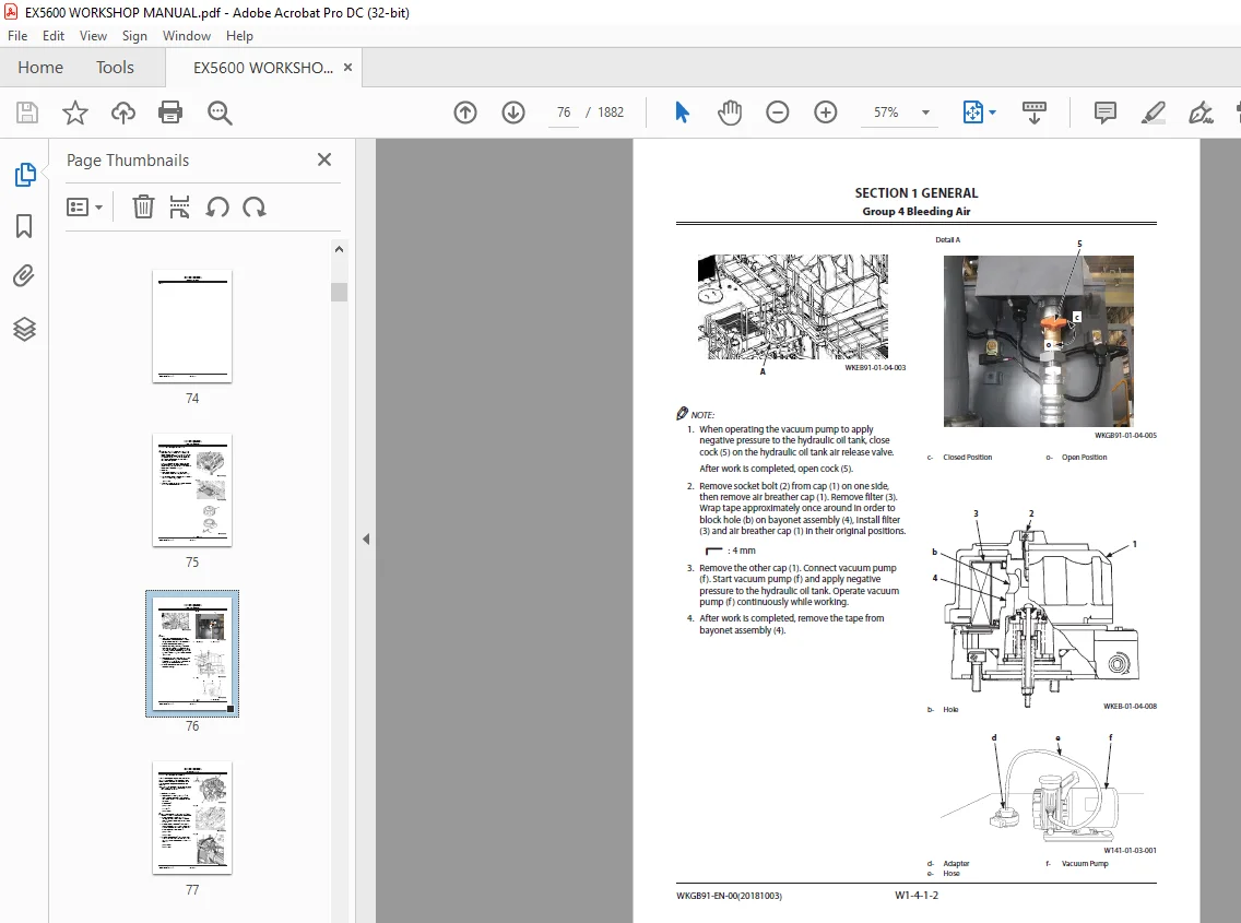
Group 4 Bleeding Air 75
Bleeding Air from Hydraulic Oil Tank 75
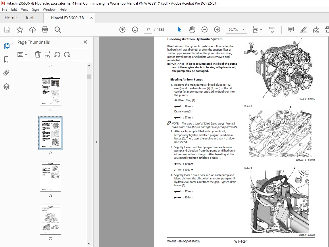
Bleeding Air from Hydraulic System 77
Bleeding Air from Fuel System 81
Bleeding Air from Water Tank 83
Group 5 Releasing Pressure 85
Releasing Pressure in Hydraulic Circuit 85
Group 6 Preparation 87
Preparation before Inspection and Maintenance 87
SECTION 2 MAINTENANCE STANDARD 91
Group 1 Upperstructure 93
Pump Device 93
Swing Motor 97
Group2 Undercarriage 101
Travel Motor 101
Drive Tumbler 105
Front Idler 107
Upper Roller 109
Lower Roller 111
Track 113
Group 3 Loader Front Attachment 115
Pin and Bushing 115
Point, Shroud 117
Cylinder 119
SECTION 3 UPPERSTRUCTURE 123
Group 1 Cab 125
Removal and Installation of Cab 125
Dimensions of Cab Glass 155
Removal and Installation of Escape Device 161
Group 2 Cab Bed 163
Removal and Installation of Cab Bed Blower Motor 163
Removal and Installation of Air Conditioner Unit 165
Removal and Installation of Air Conditioner Compressor Motor 173
Disassembly of Air Conditioner Compressor Motor 179
Removal and Installation of Air Conditioner Compressors 187
Removal and Installation of Air Conditioner Condensers 191
Work When Replacing Components of Air Conditioner 195
Recover Refrigerant 196
Refill Compressor Oil 197
Charge Air Conditioner with Refrigerant 198
Group 3 Counterweight 207
Removal and Installation of Counterweight 207
Group 4 Upperstructure 227
Removal and Installation of Upperstructure 227
Group 5 Engine Unit 475
Removal and Installation of Engine (Left Frame) 475
Removal and Installation of Engine (Right Frame) 563
Removal and Installation of Radiator (Left Frame) 659
Removal and Installation of Radiator 685
Removal and Installation of Oil Cooler Core 711
Removal and Installation of Oil Cooler Fan Motor 749
Structure of Oil Cooler Fan Motor 783
Group 6 Pump Device 785
Removal and Installation of Pump Device (Left Frame) 785
Preparation 786
Removal of Related Parts 788
Removal of Hoses and Pipes 801
Removal of Electrical Parts 815
Removal of Pump Device 828
Installation of Pump Device 832
Installation of Electrical Parts 837
Installation of Pipes and Hoses 850
Installation of Related Parts 864
Work After Installation 877
Removal and Installation of Pump Device (Right Frame) 881
Preparation 882
Removal of Related Parts 884
Removal of Hoses and Pipes 897
Removal of Electrical Parts 911
Removal of Pump Device 924
Installation of Pump Device 928
Installation of Electrical Parts 933
Installation of Pipes and Hoses 946
Installation of Related Parts 960
Work After Installation 973
Disassembly and Assembly of Pump Transmission 977
Disassembly and Assembly of Main Pump 989
Disassembly and Assembly of Regulator for Main Pump1007
Structure of 4-Unit Pump1013
Disassembly and Assembly of Oil Cooler Fan Motor Drive Pump1015
Disassembly and Assembly of Regulator for Oil Cooler Fan Motor Pump1029
Structure of Air Conditioner Compressor Motor Pump, Pilot Pump1041
Structure of Pump Transmission Oil Pump1045
Group 7 Control Valve1047
Removal and Installation of Control Valve1047
Disassembly of Control Valve1205
Pilot Port Position1206
Layout of Relief Valves and Make-up Valves1207
Assembly of Control Valve1214
Group 8 Other Valves1221
Removal and Installation of EDQR Valve1221
Structure of EDQR Valve1235
Structure of Proportional Solenoid Valve1237
Group 9 Swing Device1239
Removal and Installation of Swing Device1239
Swing Device (Rear Right Side)1258
Disassembly and Assembly of Swing Reduction Gear1269
Disassembly and Assembly of Swing Motor1277
Disassembly and Assembly of Valve Unit1301
Group 10 Aftertreatment Device1307
Removal and Installation of Urea SCR Muffler Unit (Left Frame)1307
Removal and Installation of Urea SCR Muffler Unit (Right Frame)1319
Removal and Installation of DEF Tank (Left Frame)1331
Removal and Installation of DEF Tank (Right Frame)1355
Removal and Installation of DEF Hose (Left Frame)1379
Removal and Installation of DEF Hose (Right Frame)1383
Group 11 Hydraulic Oil Tank1387
Removal and Installation of Hydraulic Oil Tank1387
Group 12 Fuel Tank1417
Removal and Installation of Fuel Tank1417
Group 13 Lift Cylinder (Fast-Filling System)1441
Removal and Installation of Lift Cylinder (Fast-Filling System)1441
Disassembly and Assembly of Lift Cylinder (Fast-Filling System)1449
Assembly of Lift Cylinder (Fast-Filling System)1452
Group 14 Lift Cylinder (Retractable Stairway)1457
Removal and Installation of Lift Cylinder (Retractable Stairway)1457
Disassembly of Lift Cylinder (Folding Stairway)1465
Assembly of Lift Cylinder (Folding Stairway)1467
SECTION 4 UNDERCARRIAGE1471
Group 1 Swing Bearing1473
Removal and Installation of Swing Bearing1473
Group 2 Travel Device1487
Removal and Installation of Travel Device1487
Disassembly and Assembly of Travel Reduction Gear1503
Disassembly and Assembly of Travel Motor1515
Disassembly and Assembly of Travel Mode Selector Valve1533
Group 3 Travel Brake Valve1541
Removal and Installation of Travel Brake Valve1541
Disassembly and Assembly of Travel Brake Valve1551
Group 4 Drive Tumbler1555
Removal and Installation of Drive Tumbler1555
Group 5 Center Joint1567
Removal and Installation of Center Joint1567
Disassembly of Center Joint1589
Assembly of Center Joint1593
Group 6 Adjuster Cylinder1599
Removal and Installation of Adjuster Cylinder1599
Disassembly of Adjuster Cylinder1603
Disassembly of Adjuster Cylinder1606
Group 7 Front Idler1611
Removal and Installation of Front Idler1611
Disassembly and Assembly of Front Idler1615
Group 8 Upper and Lower Rollers1619
Removal and Installation of Upper Roller1619
Removal and Installation of Lower Roller1623
Disassembly and Assembly of Upper Roller1627
Assembly of Upper Roller1630
Disassembly and Assembly of Lower Roller1635
Assembly of Lower Roller1638
Group 9 Track1643
Removal and Installation of Track1643
Structure of Track1647
Group 10 Accumulator1649
Removal and Installation of Accumulator1649
Disassembly and Assembly of Accumulator1653
Assembly of Accumulator1655
Accumulator Maintenance Inspection1659
Inspection1660
Charging Nitrogen Gas1664
Group 11 Welding Repair Procedure1667
Welding Repair Procedure1667
Repair Track Shoes (Shoe Lugs)1669
Repair Rollers1673
Repair Drive Tumbler1677
SECTION 5 LOADER FRONT ATTACHMENT1683
Group 1 Front Attachment1685
Removal and Installation of Bucket1685
Removal and Installation of Arm1705
Removal and Installation of Boom1747
Group 2 Cylinder1767
Removal and Installation of Boom Cylinder1767
Removal and Installation of Arm Cylinder1775
Removal and Installation of Bucket Cylinder1783
Removal and Installation of Level Cylinder1791
Removal and Installation of Dump Cylinder1799
Disassembly of Cylinders1809
Assembly of Cylinders1824
Structure of Valve (Slow Return)1851
Bleeding Air Procedure1853
Group 3 Bushing1855
Removal and Installation of Bushing1855
Group 4 Angle Sensor1857
Removal and Installation of Angle Sensors1857
Group 5 Other Valves1867
Removal and Installation of 3-Spool Solenoid Valve Unit1867
Structure of 3-Spool Solenoid Valve Unit1871
Removal and Installation of Make-Up Valve1873
Disassembly of Make-Up Valve1875
Assembly of Make-Up Valve1877
SERVICE MANUAL REVISION REQUEST FORM1881
The following paper patterns are attached to this manual1882
S.M 31/1/25