Hitachi EX5600-7B Hydraulic Excavator Tier 4 Final Cummins engine Operational Technical Manual PDF
$29.95
Hitachi EX5600-7B Hydraulic Excavator Tier 4 Final Cummins engine Operational Technical Manual -PDF DOWNLOAD
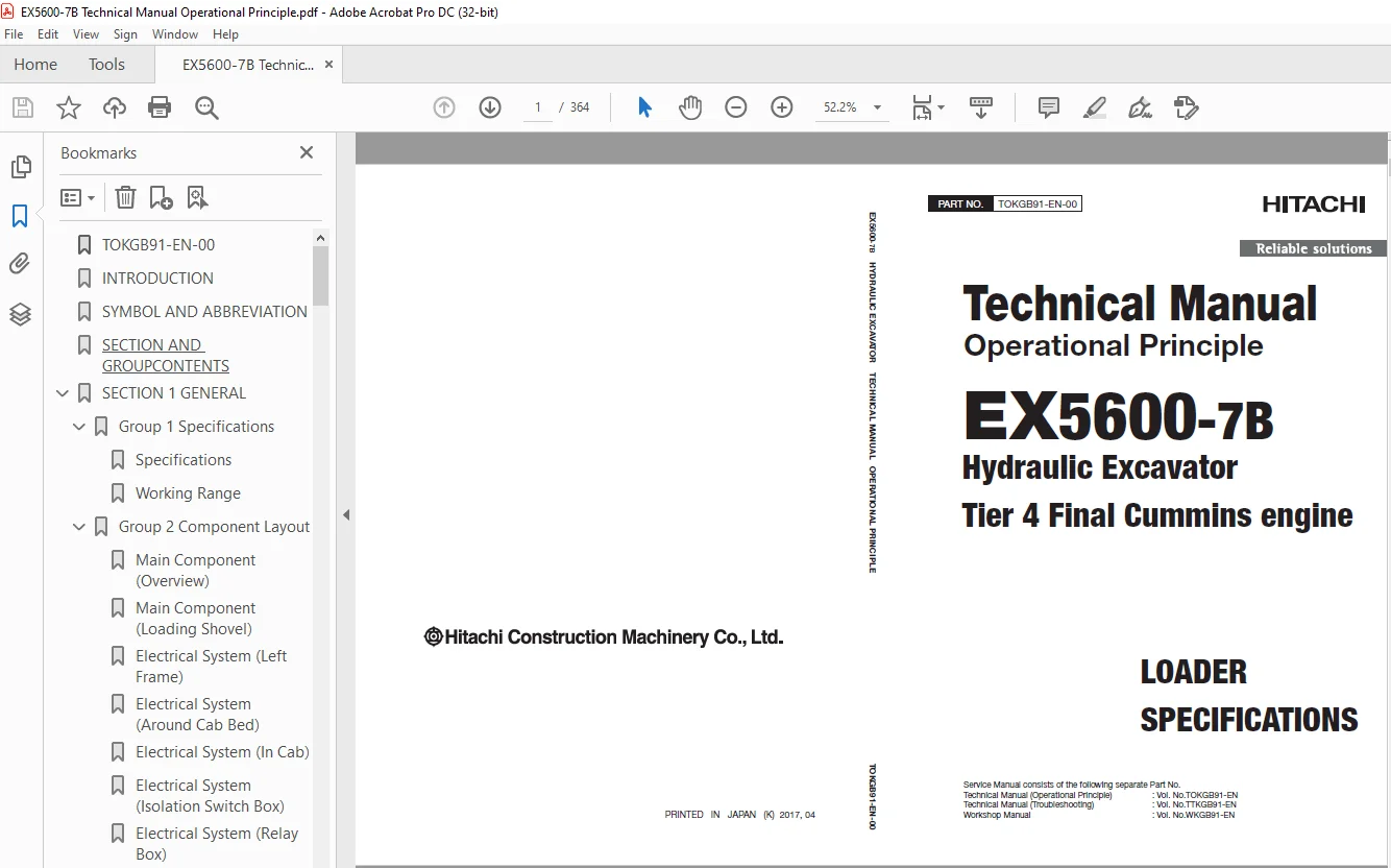
LOADER
SPECIFICATIONS
Service Manual consists of the following separate Part No.
Technical Manual (Operational Principle) : Vol. No.TOKGB91-EN
Technical Manual (Troubleshooting) : Vol. No.TTKGB91-EN
Workshop Manual : Vol. No.WKGB91-EN
Description
Hitachi EX5600-7B Hydraulic Excavator Tier 4 Final Cummins engine Operational Technical Manual -PDF DOWNLOAD
FILE DETAILS:
Hitachi EX5600-7B Hydraulic Excavator Tier 4 Final Cummins engine Operational Technical Manual -PDF DOWNLOAD
Language :English
Pages :364
Downloadable : Yes
File Type : PDF
IMAGES PREVIEW OF THE MANUAL:
DESCRIPRION:
Hitachi EX5600-7B Hydraulic Excavator Tier 4 Final Cummins engine Operational Technical Manual -PDF DOWNLOAD
LOADER
SPECIFICATIONS
Service Manual consists of the following separate Part No.
Technical Manual (Operational Principle) : Vol. No.TOKGB91-EN
Technical Manual (Troubleshooting) : Vol. No.TTKGB91-EN
Workshop Manual : Vol. No.WKGB91-EN
INTRODUCTION
This manual is written for an experienced technician to provide technical information needed to maintain and repair this machine. The machine specification and description according to destination may be explained on this manual.
Be sure to thoroughly read this manual for correct product information and service procedures.
If you have any questions or comments, at if you found any errors regarding the contents of this manual,
please contact using “Service Manual Revision Request Form” at the end of this manual. (Note: Do not tear off the form. Copy it for usage.):
Technical Information Center Hitachi Construction
Machinery Co., Ltd.
TEL: 81-29-832-7084
FAX: 81-29-831-1162
Manual Composition
- This manual consists the Technical Manual, the Workshop Manual and the Engine Manual.
- Information included in the Technical Manual: Technical information needed for redelivery and delivery, operation and activation of all devices and systems, operational performance tests, and troubleshooting procedures.
- Information included in the Workshop Manual: Technical information needed for maintenance and repair of the machine, tools and devices needed for maintenance and repair, maintenance standards, and removal / installation and assemble / disassemble procedures.
- Information included in the Engine Manual: Technical information needed for redelivery and delivery and maintenance and repair of the machine, operation and activation of all devices and systems, troubleshooting and assemble / disassemble procedures.
TABLE OF CONTENTS:
Hitachi EX5600-7B Hydraulic Excavator Tier 4 Final Cummins engine Operational Technical Manual -PDF DOWNLOAD
LOADER
SPECIFICATIONS
Service Manual consists of the following separate Part No.
Technical Manual (Operational Principle) : Vol. No.TOKGB91-EN
Technical Manual (Troubleshooting) : Vol. No.TTKGB91-EN
Workshop Manual : Vol. No.WKGB91-EN
TOKGB91-EN-00 1
INTRODUCTION 3
SYMBOL AND ABBREVIATION 5
SECTION AND GROUPCONTENTS 7
SECTION 1 GENERAL 9
Group 1 Specifications 11
Specifications 11
Working Range 12
Group 2 Component Layout 15
Main Component (Overview) 15
Main Component (Loading Shovel) 16
Electrical System (Left Frame) 17
Electrical System (Around Cab Bed) 18
Electrical System (In Cab) 19
Electrical System (Isolation Switch Box) 22
Electrical System (Relay Box) 23
Electrical System (Electrical Equipment Box) 24
Electrical System (Relay Layout of ElectricalEquipment Box) 25
Electrical System (LED Layout ofContamination Sensor Amplifier) 26
Electrical System (Monitoring Controller Box) 27
Electrical System (Left Pump CompartmentController Box) 28
Electrical System (Right Frame) 29
Electrical System (Right Pump CompartmentController Box) 30
Electrical System (Center Frame) 31
Electrical System (Angle Sensor) 32
Left Engine 33
Left Air Cleaner 34
Around Left Radiator 35
Around Left Pump 37
Left 4-Unit Pump 40
Left Pilot Panel 41
EDQR Valve 42
Left Urea SCR System 43
Folding Stairway 45
Right Engine 48
Right Air Cleaner 49
Around Right Radiator 50
Around Right Pump 52
Right 4-Unit Pump 55
Around Oil Cooler 56
Auto-Lubrication Device 57
Right Urea SCR System 58
Control Valve 60
Center Pilot Panel 64
Hydraulic Oil Tank 65
Fuel Tank 66
Fast-Filling System 67
Fast-Filling Panel 68
Swing Device 69
Center Joint 70
Travel Device 71
Undercarriage 72
Group 3 Component Specifications 73
Engine 73
Engine Accessories 77
Hydraulic Component 78
Electrical Component 82
Others 84
SECTION 2 SYSTEM 87
Group 1 Controller 89
Outline 89
MCU: Monitor Control Unit (Alarm Monitorand Sub-Control System Control Unit) 94
ELUF: Electric Lever Control Unit for Front(Electric Control Lever Controller forControlling Front Attachment Operation)100
ELUT: Electric Lever Control Unit for Travel(Electric Control Lever Controller forControlling Travel Operation)104
PFU: Pump Flow Control Unit (Pump FlowRate Control Controller)108
IDU: Information Display Unit (InformationDisplay Controller)113
ECM: Engine Control Module (EngineController)120
DLU: Data Logging Unit122
CSU: Contamination Sensing Unit124
HMU: Hydraulic System Monitoring Unit126
PMU: Pump Monitoring Unit128
EHU: Engine Heat Balance Monitoring Unit(Engine Cooling System Monitoring Unit)130
ODR: Operation Data Recorder132
BPU: Basic Performance Monitoring Unit134
Group 2 Control System137
Outline137
Engine Control139
Pump Control148
Sub-Control System Control162
Fast-Filling Panel Lower Control164
Folding Stairway Control176
Travel Mode Control180
Cab Bed Pressurization Control184
Group 3 ELU System187
Outline187
Pilot Shut-Off Control188
Boom Lower Flow Rate Regeneration Control190
Cylinder Stroke End Shock PreventionControl192
Adjuster Cylinder End Travel LimitationControl194
Swing Stop Control196
Group 4 Hydraulic System199
Outline199
Pilot Circuit200
Main Circuit204
Other Actuator Circuits220
Travel Shock Absorbing/Travel Stop Circuit221
Group 5 Electrical System223
Outline223
Main Circuit224
Electric Power Circuit (Key Switch: OFF)226
Electric Power Circuit (Key Switch: ACC)228
Electric Power Circuit (Key Switch: ON)230
Engine Starting Circuit (Engine Start Switch:ON)242
Charging Circuit (Key Switch: ON-Engine:Running)246
Engine Stop Circuit248
Surge Voltage Prevention Circuit254
Group 6 Air Conditioning System257
Outline257
Functions of Main Components258
Functions of Main Electrical Parts259
SECTION 3 COMPONENT OPERATION265
Group 1 Pump Device267
Outline267
Main Pump268
Oil Cooler Fan Motor Pump270
Regulator for Main Pump272
Regulator for Oil Cooler Fan Motor Pump280
Pump Control Solenoid Valve300
Pilot Pump, Air Conditioner CompressorMotor Pump, Pump Transmission Oil Pump,Spare Pump302
Pump Delivery Pressure Sensor302
Regulator Pressure (Flow Rate ControlPressure) Sensor302
Contamination Sensor303
Group 2 Swing Device305
Outline305
Swing Motor306
Swing Parking Brake308
Swing Reduction Gear309
Valve Unit310
Group 3 Control Valve313
Outline313
Position of Valve and Section314
Pilot Port Position316
Hydraulic Circuit318
Main Relief Valve320
Overload Relief Valve320
Make-Up Valve321
Group 4 Control Equipment323
Outline323
Electric Control Lever324
EDQR Valve for Electric Control Lever328
Group 5 Travel Device333
Outline333
Travel Motor334
Travel Mode Control336
Brake Valve340
Parking Brake342
Travel Reduction Gear343
Group 6 Others (Upperstructure)345
Oil Cooler Fan Motor345
Air Conditioner Compressor Motor347
Folding Stairway Pump Unit349
Pilot Relief Valve350
Solenoid Valve351
Reducing Valve for Travel Mode Control352
Accumulator353
Group 7 Others (Undercarriage)355
Swing Bearing355
Accumulator356
Adjuster Cylinder357
Center Joint358
Group 8 Others (Front Attachment)359
Make-Up Valve359
3-Spool Solenoid Valve Unit362
S.M 31/1/25