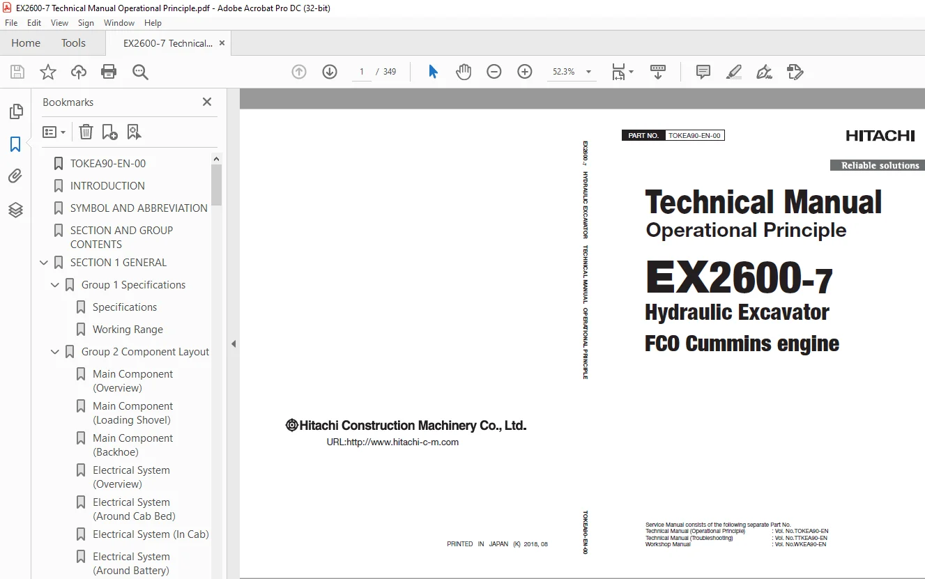
Hitachi EX2600-7 Hydraulic Excavator FCO Cummins engine Operational Technical Manual PDF
$29.95
Hitachi EX2600-7 Hydraulic Excavator FCO Cummins engine Operational Technical Manual PTTOKEA90 – PDF DOWNLOAD
Description
Hitachi EX2600-7 Hydraulic Excavator FCO Cummins engine Operational Technical Manual PTTOKEA90 – PDF DOWNLOAD
FILE DETAILS:
Hitachi EX2600-7 Hydraulic Excavator FCO Cummins engine Operational Technical Manual PTTOKEA90 – PDF DOWNLOAD
Language :English
Pages :349
Downloadable : Yes
File Type : PDF
IMAGES PREVIEW OF THE MANUAL:
DESCRIPRION:
Hitachi EX2600-7 Hydraulic Excavator FCO Cummins engine Operational Technical Manual PTTOKEA90 – PDF DOWNLOAD
- This manual is written for an experienced technician to provide technical information needed to maintain and repair this machine. The machine specification and description according to destination may be explained on this manual.
- Be sure to thoroughly read this manual for correct product information and service procedures
- If you have any questions or comments, at if you found any errors regarding the contents of this manual, please contact using “Service Manual Revision Request Form” at the end of this manual. (Note: Do not tear off the form. Copy it for usage.):
Additional References
Please refer to the other materials (operator’s manual, parts catalog, engine technical material and Hitachi training material etc.) in addition to this manual
Manual Composition
- This manual consists the Technical Manual and the Workshop Manual. Information included in the Technical Manual: Technical information needed for redelivery and delivery, operation and activation of all devices and systems, operational performance tests, and troubleshooting procedures.
- Information included in the Workshop Manual: Technical information needed for maintenance and repair of the machine, tools and devices needed for maintenance and repair, maintenance standards, and removal / installation and assemble / disassemble procedures
TABLE OF CONTENTS:
Hitachi EX2600-7 Hydraulic Excavator FCO Cummins engine Operational Technical Manual PTTOKEA90 – PDF DOWNLOAD
TOKEA90-EN-00 1
INTRODUCTION 3
SYMBOL AND ABBREVIATION 5
SECTION AND GROUP CONTENTS 7
SECTION 1 GENERAL 9
Group 1 Specifications 11
Specifications 11
Working Range 12
Group 2 Component Layout 15
Main Component (Overview) 15
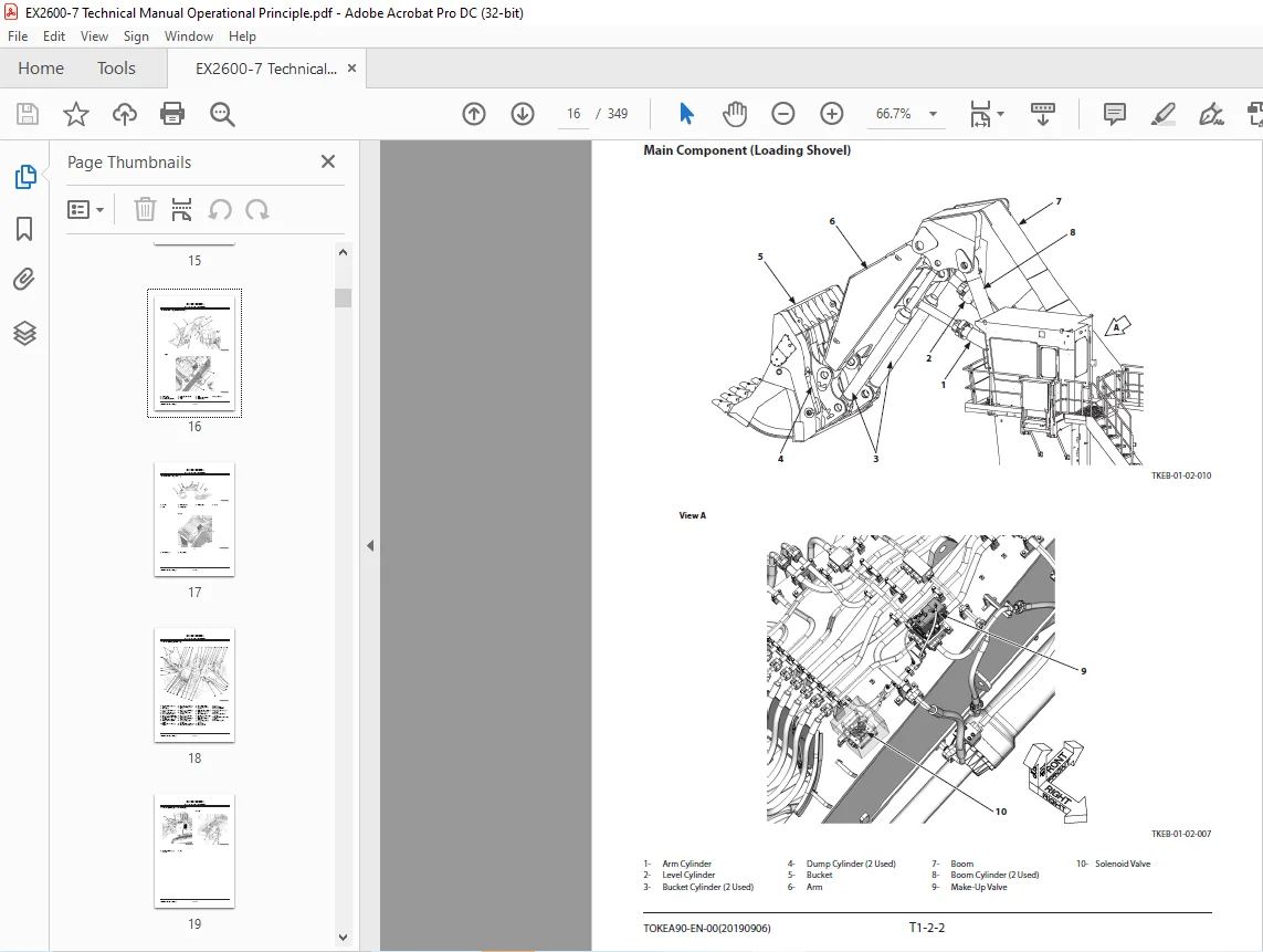
Main Component (Loading Shovel) 16
Main Component (Backhoe) 17
Electrical System (Overview) 18
Electrical System (Around Cab Bed) 19
Electrical System (In Cab) 20
Electrical System (Around Battery) 23
Electrical System (Relay Box) 24
Electrical System (Electrical Equipment Box) 25
Electrical System (Relay Layout of Electrical Equipment Box) 26
Electrical System (LED Layout of Contamination Sensor Amplifier) 27
Electrical System (Layout of Contamination Sensor) 28
Electrical System (Monitoring Controller Box) 29
Electrical System (Pump Compartment Controller Box) 30
Electrical System (Angle Sensor) (Loading Shovel) 31
Electrical System (Angle Sensor) (Backhoe) 32
Engine 33
Air Cleaner 34
Around Radiator 35
Around Oil Cooler 36
Around Pump 37
4-Unit Pump 39
Control Valve 40
Pilot Panel 43
EDQR Valve 44
Swing Device 45
Undercarriage 46
Travel Device 47
Center Joint 47
Fast-Filling System 48
Fast-Filling Panel 49
Folding Stairway 50
Auto-Lubrication Device 53
Hydraulic Oil Tank 54
Fuel Tank 55
Group 3 Component Specifications 57
Engine 57
Engine Accessories 61
Hydraulic Component 62
Electrical Component 66
Others 67
SECTION 2 SYSTEM 71
Group 1 Controller 73
Outline 73
MCU: Monitor Control Unit (Alarm Monitor and Sub-Control System Control Unit) 78
ELUF: Electric Lever Control Unit for Front (Electric Control Lever Controller for Controlling Front Attachment Operation) 84
ELUT: Electric Lever Control Unit for Travel (Electric Control Lever Controller for Controlling Travel Operation) 88
PFU: Pump Flow Control Unit (Pump Flow Rate Control Controller) 92
IDU: Information Display Unit (Information Display Controller) 97
ECM: Engine Control Module (Engine Controller)104
DLU: Data Logging Unit106
CSU: Contamination Sensing Unit108
HMU: Hydraulic System Monitoring Unit110
PMU: Pump Monitoring Unit112
EHU: Engine Heat Balance Monitoring Unit (Engine Cooling System Monitoring Unit)114
ODR: Operation Data Recorder116
BPU: Basic Performance Monitoring Unit118
Group 2 Control System121
Outline121
Engine Control123
Pump Control130
Sub-Control System Control145
Fast-Filling Panel Lower Control147
Folding Stairway Control159
Travel Mode Control163
Cab Bed Pressurization Control167
Group 3 ELU System169
Outline169
Pilot Control Shut-Off Control170
Boom Lower Flow Rate Regeneration Control172
Cylinder Stroke End Shock Prevention Control174
Adjuster Cylinder End Travel Regulation Control176
Swing Stop Control178
Group 4 Hydraulic System181
Outline181
Pilot Circuit183
Main Circuit189
Other Actuator Circuits208
Travel Shock Absorbing/Travel Stop Circuit209
Group 5 Electrical System211
Outline211
Main Circuit212
Electric Power Circuit (Key Switch: OFF)214
Electric Power Circuit (Key Switch: ACC)216
Electric Power Circuit (Key Switch: ON)218
CAN Circuit226
Starting Circuit (Key Switch: ON)228
Starting Circuit (Engine Start Switch: ON)230
Charging Circuit234
Engine Stop Circuit236
Surge Voltage Prevention Circuit242
Group 6 Air Conditioning System245
Outline245
Functions of Main Components246
Functions of Main Electrical Parts247
SECTION 3 COMPONENT OPERATION253
Group 1 Pump Device255
Outline255
Main Pump256
Oil Cooler Fan Motor Pump258
Regulator for Main Pump260
Regulator for Oil Cooler Fan Motor Pump268
Pump Control Solenoid Valve288
Pilot Pump, Air Conditioner Compressor Motor Pump, Pump Transmission Oil Pump290
Pump Delivery Pressure Sensor290
Regulator Pressure (Flow Rate Control Pressure) Sensor290
Contamination Sensor291
Group 2 Swing Device293
Outline293
Swing Motor294
Swing Parking Brake296
Swing Reduction Gear297
Valve Unit298
Group 3 Control Valve301
Outline301
Pilot Port Position302
Hydraulic Circuit303
Main Relief Valve305
Overload Relief Valve305
Make-Up Valve306
Group 4 Control Equipment307
Outline307
Electric Control Lever308
EDQR Valve for Electric Control Lever312
Group 5 Travel Device317
Outline317
Travel Motor318
Travel Mode Control320
Brake Valve324
Parking Brake326
Travel Reduction Gear327
Group 6 Others (Upperstructure)329
Oil Cooler Fan Motor329
Air Conditioner Compressor Motor331
Folding Stairway Pump Unit333
Pilot Relief Valve334
Travel Mode Selector Solenoid Valve335
Reducing Valve for Travel Mode Control336
Accumulator337
Group 7 Others (Undercarriage)339
Swing Bearing339
Accumulator340
Adjuster Cylinder341
Center Joint342
Group 8 Others (Front Attachment)343
Make-Up Valve343
3-Spool Solenoid Valve Unit346
SERVICE MANUAL REVISION REQUEST FORM349
S.M 30/1/25