

Hein-Werner Series 10 10HD & 12HD Hydraulic Backhoes Service & Parts Manual – PDF DOWNLOAD
DESCRIPTION:
Hein-Werner Series 10 10HD & 12HD Hydraulic Backhoes Service & Parts Manual – PDF DOWNLOAD
HYDRAULIC CIRCUITS. AND CONTROLS
- The information in this section is designed to furnish the owner and operator of Hein-Werner back hoes with the basic information needed to understand the operation of the ·machine. An understanding of the various systems is essential to proper operation and service, and we suggest this description be read thoroughly.
- models of the backhoe, though they vary in size to provide different digging depths and reaches, operate in the same manner.
- Power is supplied by either a gasoline or diesel engine (24, Figure 1) the make of which is optional. (For service parts and in formation, refer to the engine manual supplied with your machine.) The engine is ·coupled to the hydraulic pump by either a direct drive shaft or a clutch (23). The clutch is extremely useful as a starting aid in cold weather. (If your machine is equipped with a clutch, refer to the separate section included with this manual.)
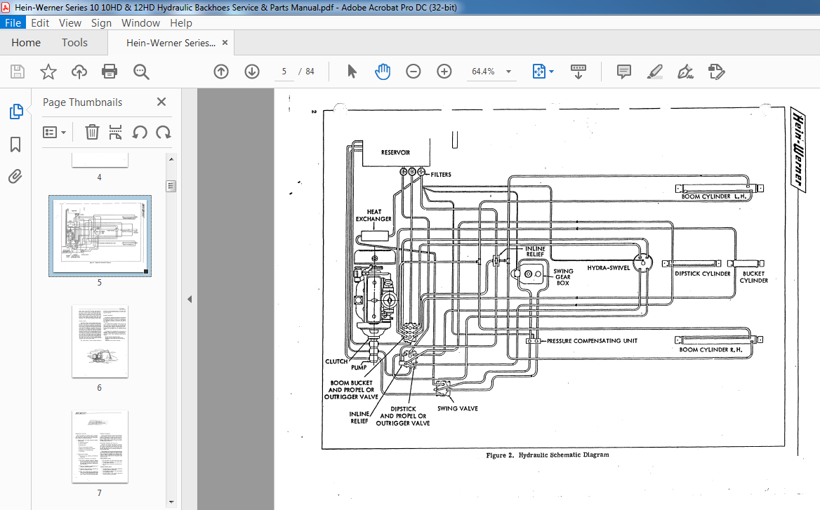
- Figure 2 illustrates the hydraulic circuits schematically. Refer to it while reading the following description. The pump is a gear type, with three sections in tandem, mounted directly to the engine clutch housing. Each pump section is fitted with a separate supply line from the reservoir to assure proper oil flow.
- The pump section (22, Figure 1) closest to the engine delivers high pressure oil to the boom, bucket, and propel control valve (18) OJ\ the crawler mounted machine, and to the boom, bucket, and outrigger sys term on the carrier mounted machine.
- The center pump section (21) supplies high pressure oil to the dipstick and propel circuit valve (19) on the crawler mounted machine and to the dipstick and outrigger system on the carrier mounted machine.
- The pump section (20) furthest from the engine delivers high pressure oil to the swing control valve (16) on all models. The three pump sections are completely independent of each other enabling simultaneous use of all. three circuits.
- When the two control valves (18 and 19) are in neutral position, the oil flows through the valve and return lines (2) to the filters (3) mounted on the hydraulic reservoir (1). When the swing control valve
- (16) is in neutral position, the oil flows through the valve, return line (26), heat exchanger (25) and then through a filter.
- The heat exchanger uses air drawn through the radiator by the engine to cool the oil. Each hydraulic circuit includes a filter which contains. a removable filtering element that can be recleaned or replaced. After being filtered, the oil flows directly’ into the reservoir.
- The filters include a pressure gage which is visible from the cab and indicates the condition of the filter element. When the gage pointer is in the red zone, the element must be cleaned, or replaced.
- The control valves are operated by levers (12); and foot pedals (13) in the operator’s cab. The cab is also equipped with a complete set of engine gages and controls. The engine gage set consists of an ammeter, gages for fuel level, oil pressure and water temperature, and a combination tachometer and engine revolution hour meter.
- When a typical cylinder circuit is put into operation by moving the control lever or foot pedal in either direction from the neutral position, the valve spool moves within the control valve. This spool reroutes the oil flow from the return line port to the port which supplies oil to the cylinder being used.
- This spool is spring loaded to return to neutral position when the control lever or pedal is released. The control valves have excellent ”feathering” characteristics to assure smooth and precise operation of all components.
- The control valves contain a relief valve which is adjusted at the factory to a specified limit. If the pressure demanded by the circuit being used exceeds this pre-set limit, the relief valve will bypass the oil to the reservoir until the pressure demanded by the circuit drops to the specified pressure setting.
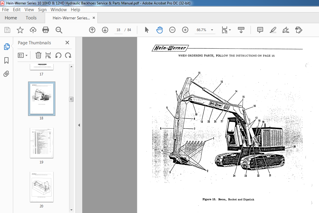
- The digging members are also protected from overload by an inline pressure compensating unit (17). This unit relieves the pressure in the boom and dipstick circuits when external forces cause the pressure to exceed the maximum allowable. The swing circuit is controlled by the single
TABLE OF CONTENTS:
Hein-Werner Series 10 10HD & 12HD Hydraulic Backhoes Service & Parts Manual – PDF DOWNLOAD
SECTION I — BACKHOE DESCRIPTION
Hydraulic Circuits and Controls
Swing System
Digging Members
SECTION II — BACKHOE OPERATION
Preparation for Use
Starting the Engine
Operating Controls
Digging Hints
Stopping the Engine
Preparation for Storage
SECTION III — BACKHOE MAINTENANCE AND REPAIR
Maintenance
Maintenance Schedules
Hydraulic Circuit Pressure Checks
Tool Kit
Repair
Shaft Bearing Adjustment
Hydraulic Cylinder Repair
SECTION IV — REPAIR PARTS LIST
VIDEO PREVIEW OF THE MANUAL:

IMAGES PREVIEW OF THE MANUAL:
PLEASE NOTE:
- This is the SAME exact manual used by your dealers to fix your vehicle.
- The same can be yours in the next 2-3 mins as you will be directed to the download page immediately after paying for the manual.
- Any queries / doubts regarding your purchase, please feel free to contact [email protected]


