Heidenhain iTNC 530 Technical Manual 2011 – PDF DOWNLOAD
$34.95
Heidenhain iTNC 530 Technical Manual 2011 – PDF DOWNLOAD
NC Software
340 490-06
340 491-06
340 492-06
340 493-06
Description
Heidenhain iTNC 530 Technical Manual 2011 – PDF DOWNLOAD
FILE DETAILS:
Heidenhain iTNC 530 Technical Manual 2011 – PDF DOWNLOAD
Language :English
Pages :1897
Downloadable : Yes
File Type : PDF
IMAGES PREVIEW OF THE MANUAL:
DESCRIPTION:
Heidenhain iTNC 530 Technical Manual 2011 – PDF DOWNLOAD
NC Software
340 490-06
340 491-06
340 492-06
340 493-06
1 Update Information
1.1General Information
- Update Information for the iTNC 530 appears at irregular intervals, often as part of a new software version. This is preliminary information in PDF format, containing brief descriptions of new software functions as well as new hardware components. After the Update Information has been published, the new items are included in the iTNC 530 Technical Manual.
- The Technical Manual and each Update Information are saved in the HEIDENHAIN FileBase on the Internet, where registered users can access them at Registered users of the HEIDENHAIN FileBase on the Internet receive an e-mail notification when a new Update Information appears.
- This version of the Technical Manual includes all 24 Update Information notifications that have appeared so far, meaning that the contents of this Technical Manual for the iTNC530 correspond to the scope of functions of software version 34049×06.
TABLE OF CONTENTS:
Heidenhain iTNC 530 Technical Manual 2011 – PDF DOWNLOAD
1 Update Information 21
11 General Information 21
1 Update Information No 25 – Introduction of HSCI 23
11 Overview 23
111 Released service packs 23
112 Released NC software 23
12 iTNC 530 with HSCI 24
121 Important notes 24
122 Description of the new functions 26
123 iTNC – Operation and technology 38
13 HSCI 40
131 Introduction 40
132 HSCI interface 42
133 Special features of the software 43
134 HeROS 5 operating system 45
135 Emergency stop monitoring 47
136 Topology and cables 50
137 Bus diagnosis 54
138 Supply voltages in the HSCI system 61
139 Power supply for PLC outputs 65
1310 Power supply for PLB 6xxx 66
1311 Power supply for control-is-ready signal 67
14 Overview of Components 68
15 Mounting Position of MC 6xxx, CC 61xx, UV xxx, UM xxx, UE 2xx B 72
16 Storage and Operating Temperatures 73
161 Limit values 73
162 Limit value for temperature inside the panel 74
163 Humidity during operation 74
164 Storage temperatures 74
165 Limit values for ambient conditions 75
17 MC 6xxx Main Computer, HDR and SIK 76
171 General information 76
172 Connection overview 80
173 USB interface (USB 20) 82
174 Ethernet interface 82
175 HDL interface 83
176 Handling the HDR hard disk 84
177 Mounting the Solid State Disk (SSD) 85
178 Buffer battery 86
18 CC 61xx Controller Unit 88
181 General information 88
182 Structure and performance of the controller unit 93
183 New functions of the CC 61xx 101
184 Specifications 105
185 Example configuration 107
186 Connection overview 109
19 UEC 11x Controller Unit with Integrated Inverter and PLC 113
191 Meaning of the LEDs 121
110 PL 6xxx 122
1101 General information 122
1102 I/O modules 124
1103 Connection overview of PLB 62xx 126
1104 Connection overview of PLB 61xx 126
1105 PLD/PLA connection overviews 127
1106 X9: Safety-related PLC inputs/outputs 129
1107 Configuration with IOconfig 133
1108 PLC inputs/outputs 136
1109 Analog PLC inputs/outputs 139
11010 Switching inputs 24 V- (PLC) 141
111 UEC 11x: Digital PLC Inputs/Outputs 142
112 PSL13x Low-Voltage Power Supply Unit 145
1121 General information 145
1122 Specifications 147
1123 Connection overview 149
113 MS 110 / MS 111 Mounting Case for Double-Row Configuration 157
1131 General information 157
1132 Double-row configuration 159
1133 Connection overview 161
114 MB 620 Machine Operating Panel 166
115 HSCI Adapter for PLB 6001 OEM-Specific Machine Operating Panel 173
116 TE 620 Keyboard Unit 177
117 TE 630 Keyboard Unit 179
118 TE 635Q Keyboard Unit 181
119 BF 250 15-Inch TFT Screen 182
120 Cable Overviews 185
1201 Control Systems with CC; MC in Electrical Cabinet 185
1202 Control Systems with CC; MC in Electrical Cabinet 186
1203 Accessories 187
121 Dimensions 188
1211 MC 6×41 188
1212 MC 6222 189
1213 CC 6106 190
1214 CC 6108 / CC 6110 191
1215 UEC 11x 192
1216 PLB 6xxx (FS) 193
1217 PLB 6001 (FS) 194
1218 PSL 130 195
1219 PSL 135 196
12110 MS 11x 197
12111 MB 620 198
12112 TE 535Q 199
12113 TE 630 200
12114 TE 620 201
12115 BF 250 202
1 Update Information No 26 – Revised Version 203
11 Overview 203
111 Released service packs 203
12 NC Software 340 49x-xx, 606 42x-01 203
121 Important notes 203
1 Update Information No 27 207
11 Overview 207
111 Released service packs 207
12 NC Software 340 492-xx, 340 493-xx 207
121 Important notes 207
1 Update Information No 28 209
11 Overview 209
111 Released service packs 209
12 NC Software 340 49x, 606 42x 209
121 Space characters in path and file names 210
122 Brake test for synchronized axes 211
123 New Functions 217
1 Update Information No 29 219
11 Overview 219
111 Released service packs 219
12 New Hardware – HR 550FS Wireless Handwheel 219
121 HR 550 wireless handwheel 221
122 Radio transmission regulations 225
123 General information 226
124 Connecting the wireless handwheel system 228
125 Settings 233
126 Prerequisites for use of the wireless handwheel system 234
127 Important notes on the radio network of the wireless handwheel system 235
128 Checking the radio environment at the intended place of use 236
129 Information in the handwheel configuration dialog 239
1210 Dimensions 242
13 More Information 244
1 Update Information No 30 245
11 Overview 245
111 Released service packs 245
12 NC Software 340 49x-06, 606 42x-01 245
2 Introduction 247
21 General Information 247
211 Meaning of the symbols used in this manual 247
212 Proper operation 248
213 Trained Personnel 249
22 Overview of Components 250
221 Main computer, hard disk and SIK 250
222 CC controller units 256
223 UV 106B power supply unit 259
224 UV 105B (non-HEIDENHAIN inverter systems) 261
225 UV 105 power supply unit 262
226 Keyboard units and monitors 263
227 Handwheels 268
228 Key symbols 272
229 Touch probes 277
2210 MS110, MS111 installation kit 279
2211 Other accessories 280
2212 Documentation 286
23 Brief Description 287
24 Software 301
241 Designation of the software 301
242 PLC software 302
243 Additional Control Loops or Software Options 302
244 Upgrade Functions (Feature Content Level) 311
245 NC software exchange on the iTNC 530 313
246 Installing a service pack 327
247 Data backup 329
3 Mounting and Electrical Installation 331
31 General Information 331
311 Safety precautions 331
312 Degrees of protection 332
313 Electromagnetic compatibility 332
314 ESD protection 333
32 Handling of the HDR Hard Disk and the SIK 335
33 Environmental Conditions 337
331 Heat generation and cooling 337
332 Humidity 338
333 Installation elevation 338
334 Mechanical vibration 338
335 Mounting attitude of MC 42x(B,C), CC 42x, UV xxx, UM xxx, UE 2xx B 339
336 Mounting position of display 340
34 Connection Overview for iTNC 530 341
35 Power Supply for the iTNC 530 351
351 UV 105 power supply unit 353
352 UV 105B (non-HEIDENHAIN inverter systems) 356
353 UV106B power supply unit 361
36 Power Supply for PLC Outputs 365
361 Power supply for PL 4xx B 367
362 Power supply for PL 51x 369
37 Power Supply for Control-Is-Ready Signal 370
38 Power Supply for the Display Units 370
39 Buffer Battery 371
310 Drive Controller Enable 373
311 Encoder Connections 375
3111 General information 375
3112 Input of position encoder 376
3113 Input of speed encoder 378
312 Adapters for Encoder Signals 382
313 Motor Power Stage Connection 386
314 Analog Input 387
315 Analog Nominal Value Output 391
3151 Nominal value output 391
316 Touch Probe Systems 395
3161 Triggering touch probe for workpiece measurement 395
3162 Triggering touch probe for tool measurement 397
317 Data Interfaces 399
318 Handwheel Input 404
3181 HR 4xx or HR 5xx portable handwheel 405
3182 HR 130 panel-mounted handwheel 408
3183 HRA 110 handwheel adapter 408
319 Input for Spindle Reference Signal 410
320 Switching Inputs 24 V- (PLC) 411
3201 Input signals and addresses 411
3202 PLC inputs on the PL 410B 413
3203 PLC inputs on the PL 405B 415
3204 PLC inputs on the PL 51x 416
321 Switching Outputs 24 V- (PLC) 0
322 PLC Input/Output Units 424
3221 PL 4xx B 424
3222 PL 510 427
323 PLB 511/PLB 512 431
324 Machine Operating Panel 438
325 iTNC Control Panel 445
326 Flat-Panel Display 447
327 BTS 1×0 Monitor/Keyboard Switch Unit 452
328 MS110 / MS111 Installation Kit 454
329 USB Interface 461
330 CML 110 Capacitor Module 464
331 Cable Specifications 465
332 Dimensions 466
3321 MC 420 and CC 422 with 6 Control Loops 466
3322 MC 422B / 5 position encoder inputs and CC 422 with 6 control loops 467
3323 MC 422C / 5 position encoder inputs and CC 422 with 6 control loops 468
3324 MC 422C DP/CC 422 with 6 control loops 469
3325 MC 422B/CC 424(B) with 6 control loops 470
3326 MC 422C/CC 424(B) with 6 control loops 471
3327 MC 422C DP/CC 424(B) with 6 control loops 472
3328 MC 422B/CC 424(B) with 8 control loops 473
3329 MC 422C/CC 424(B) with 8 control loops 474
33210 MC 422B / 10 position encoder inputs and CC422 with 10 control loops 475
33211 MC 422B/CC 424(B) with 10 control loops 476
33212 MC 422B / 10 position encoder inputs and CC 422 with 10 or 12 control loops 477
33213 MC 422C/CC 424(B) with 10 control loops 478
33214 MC 422B/CC 424(B) with 12 and with 14 control loops 479
33215 MC 422C/CC 424(B) with 12 and with 14 control loops 480
33216 UV 105 481
33217 TE 420 482
33218 TE 520B / TE 530 / TE 530B 483
33219 TE 535Q 484
33220 MB 520 485
33221 MB 420 486
33222 BF 120 487
33223 BF 150 488
33224 BTS 120/BTS 150 489
33225 PL 4xx B 490
33226 PL 51x 491
33227 Adapter block for the data interface 492
33228 MS 11x 493
33229 USB hub 494
33230 Line-drop compensator 495
33231 Handwheels 495
33232 Touch probe systems 503
33233 CML 110 510
33234 USB hub for operating panel 511
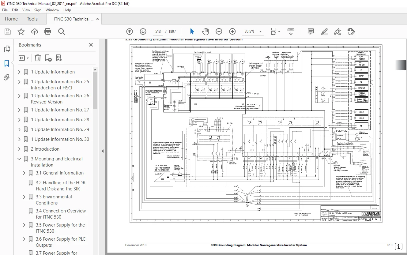
333 Grounding Diagram: Modular Nonregenerative Inverter System 513
334 Grounding Diagram: Modular Regenerative Inverter System 514
335 Grounding Diagram: UE 2xxB Nonregenerative Compact Inverter 515
336 Grounding Diagram for iTNC 530 with UR 2xx Compact Inverter 516
337 Cable Overview for iTNC 530 – Basic Configuration 517
338 Cable Overview for iTNC 530 with HEIDENHAIN Inverter Systems 518
339 Cable Overview for iTNC with SIMODRIVE / POWER DRIVE 519
340 Cable Overview for iTNC 530 – Accessories 520
4 Machine Parameters 521
41 What is a Machine Parameter? 521
42 The “Machine Parameter Programming” Mode of Operation 523
43 Input and Output of Machine Parameters 524
431 Input Format 524
432 Activating the Machine Parameter List 526
433 Changing the Input Values 526
44 List of Machine Parameters 538
441 Encoders and Machines 538
442 Positioning 545
443 Operation with Velocity Feedforward Control 554
444 Operation with Following Error (Servo Lag) 555
445 Integrated Speed and Current Control 556
446 Spindle 568
447 Integral PLC 572
448 Configuration of the Data Interface 575
449 3-D Touch Probe 577
4410 Tool Measurement with TT 580
4411 Tapping 585
4412 Display and Operation 586
4413 Colors 596
4414 Machining and Program Run 600
4415 Hardware 610
4416 Second Spindle 623
5 Modules, Markers and Words 625
51 Overview of Modules 625
52 Overview of Markers and Words 633
6 Configuring the Axes and Spindle 645
61 Control Loops 645
611 Selecting the Axes 645
612 Axis Designation 646
613 Encoders 648
614 Assignment for Axes 655
615 Assignment for Spindles 656
616 Reading Axis Information 659
617 Traverse Ranges 661
618 Lubrication Pulse 667
62 PLC axes 669
621 Coupling function for PLC axes or auxiliary axes 673
63 PLC Positioning 679
64 Axis Error Compensation 686
641 Backlash compensation 686
642 Linear axis error compensation 690
643 Nonlinear axis error compensation 691
644 Compensation of Thermal Expansion 697
645 Compensation of Reversal Spikes during Circular Traverse 699
646 Compensation of Stick-Slip Friction 701
647 Compensation of Sliding Friction (Only for Digital Axes) 703
648 Torsion Compensation 704
65 Tilting Axes 705
651 Determining the Mechanical Offset 705
652 Calculating the Mechanical Offset up to Software 340 422-xx 719
653 Description for Configuring the Kinematics as of Software 340 490-xx 723
654 Temperature Compensation with Tilting Axes 752
655 Changing the Milling Heads 756
656 KinematicsOpt 757
657 “Tilt Working Plane” Feature 772
658 Automatic Compensation of Offset for Tilting Axes 780
659 Virtual Tool Axis 784
6510 Tilting functions with open-loop rotary axes 785
6511 Cylindrical Surface 785
66 Synchronized Axes 787
661 Gantry Axes 787
662 Master-Slave Torque Control 790
67 Reference Marks 799
671 Definition 799
672 Traversing the Reference Marks 800
68 The Control Loop 813
681 Relation Between Jerk, Acceleration, Velocity and Distance 815
682 Interpolator 817
683 Position controller 843
684 Speed Controller 859
685 Switching Drives On and Off 869
686 Current Controller 878
687 Braking the Drives for an Emergency Stop and a Power Fail 880
688 Power and Torque Limiting 883
689 Weakened Field Operation 890
69 Offset Adjustment 893
691 Offset Adjustment with Integral Factor 893
692 Offset Adjustment by Code Number 893
610 Contouring behavior 894
6101 Radial Acceleration 894
6102 Contour Velocity at Corners 894
611 Monitoring Functions 897
6111 Position Monitoring 899
6112 Nominal Speed Value Monitoring 902
6113 Movement Monitoring 903
6114 Standstill Monitoring 904
6115 Positioning Window 904
6116 Monitoring of the Power Supply Unit 906
6117 Temperature monitoring 908
6118 Internal power supply and housing fan 910
6119 I2t monitoring 910
61110 Momentary utilization of drive motors 921
61111 Determining the current torque of a drive 922
61112 Status of HEIDENHAIN inverters 923
61113 Controlling the motor brakes 926
61114 EMERGENCY STOP monitoring 932
61115 EN 13849-1 940
612 Spindle 941
6121 Position encoder of the spindle 942
6122 Speed encoder of the spindle 946
6123 Analog and digital closed-loop spindle control 948
6124 Coded output of spindle speed 961
6125 Volts-per-hertz control mode 963
6126 Oriented Spindle Stop 964
6127 Tapping with floating tap holder and nominal speed output 970
6128 Tapping with floating tap holder and coded spindle-speed output 972
6129 Rigid tapping 973
61210 Switching the modes of operation 976
61211 Operating a second spindle 981
61212 C-axis operation 983
613 Integrated Oscilloscope 987
614 Commissioning 998
6141 Tables for power modules, supply modules and motors 998
6142 PWM frequencies of the CC 4221012
6143 Field Orientation1016
6144 Preparation1020
6145 Commissioning digital control loops with TNCopt1023
6146 Commissioning of digital axes1026
6147 Commissioning the digital spindle1054
6148 Commissioning an analog axis1059
6149 Commissioning the analog spindle1063
615 Block Diagram of iTNC 530 (with CC 422)1065
616 Block Diagram of iTNC 530 (with CC 424)1066
617 Block Diagram of iTNC 530 (with Analog Control Unit)1067
7 CC 424(B) Controller Unit1068
71 Differences Between the CC 424(B) and CC 4221068
72 Connecting the Encoders1070
721 General information1070
722 Position encoders1070
723 Speed encoders1070
73 Relationship between Speed Input and PWM Output1071
74 Relationship between PWM Output and Position Input1072
75 Single-Speed, Double-Speed, PWM Frequency1073
751 General information1073
752 Prerequisites1074
753 Machine parameters1074
754 Setting the controller performance in MP 7610×1074
755 PWM frequency1077
76 PLC Cycle Time1082
77 Monitoring Functions1083
78 Special Functions1085
781 Multifunction Filter1085
782 Filter order for separate low-pass filter in the speed controller1089
783 Dynamic determination of load1089
784 LIFTOFF function in case of a power failure1091
785 TRC – Torque Ripple Compensation1094
786 Peculiarities in weakened-field operation1096
79 Stick-Slip Friction Compensation at Quadrant Transitions1098
710 Field Orientation1100
7101 Possibilities for determining the field angle1102
7102 Determination of the field angle without motor motion (MP2254x = 0)1105
7103 Determination of the field angle with motor motion (MP2254x = 2/3)1107
7104 Reading or setting the field angle via the PLC1110
7105 Saving the determined field angle1112
7106 Definition of the field angle1113
711 Adjustment of Linear and Torque Motors1114
7111 General information1114
7112 Safety precautions for linear and torque motors1118
712 Commissioning Linear and Torque Motors1120
7121 Machine parameters for linear motors1120
7122 Machine parameters for torque motors1121
7123 Adjustment of the current controller1122
7124 Adjustment of the speed controller1125
713 Determining Entries for Motor Tables1131
7131 Determining data for linear motors1131
7132 Determining data for torque motors1134
8 Machine Interfacing1138
81 Display and Operation1138
811 Position and status display1138
812 Operating modes1154
813 Operating times1158
814 Error messages1164
815 Service files1172
816 Help1176
817 PLC pop-up window1179
818 TNCguide – context-sensitive help system for the iTNC 530 (user documentation)1182
819 Machine datum1192
8110 NC program1196
8111 Adaptive feed control (AFC)1202
8112 Global program settings (PGM)1219
8113 Cycles1221
8114 End of program run1224
8115 Returning to the contour1224
8116 M functions1232
8117 Powering up and shutting down the control1241
8118 Arc end-point tolerance1244
8119 Limit-switch tolerance for M140 / M1501244
8120 Radius compensation1245
8121 User Parameters1245
8122 Code numbers1246
8123 Programming Station mode1247
8124 Color settings1247
8125 Graphic display1253
8126 Special characters1255
8127 iTNC character set1256
8128 Conversational language1261
8129 Logs1264
8130 Diagnostic functions1275
8131 Window Manager1297
82 PLC Window1301
821 Small PLC window1301
822 Large PLC window1305
83 PLC Soft Keys1319
831 Soft-key project file for screen1319
832 Soft-key project file for HR 4201332
833 Compatibility with TNC 426/TNC 4301336
84 Keystroke Simulation1339
841 iTNC control panel1339
842 Machine operating panel1351
843 Touchpad on USB port1352
85 Files1354
851 Datum tables (*D)1357
852 Freely definable tables1357
853 PLC files1367
86 DCM – Dynamic Collision Monitoring1372
861 DCM – monitoring the working space for collisions1372
862 Fixture monitoring with DCM1401
863 Tool carrier kinematics and DCM1425
864 KinematicsDesign1435
87 Pallet Management1437
88 Electronic Handwheel1446
881 HR 130 panel-mounted handwheel1452
882 HR 410 portable handwheel1452
883 HR 420 portable handwheel1454
884 HR 520 portable handwheel1458
885 HR 150 panel-mounted handwheels with HRA 110 handwheel adapter1460
89 PLC Inputs/Outputs1462
891 24 V- switching input/outputs1467
892 Analog inputs1471
893 Analog outputs1474
810 Incremental Jog Positioning1475
811 Hirth coupling1477
812 Datum Shift1479
813 Touch Probe1480
8131 Using the touch probes1480
8132 Touch probe cycles1484
8133 Measurement log in manual touch probe cycles1491
8134 Measurement log in the touch probe cycles for probing from the NC program1494
8135 Tool measurement1497
814 Special Functions for Laser Cutting Machines1508
8141 Analog voltage output1508
8142 Graphic simulation (without TOOL CALL)1510
8143 Program stop for M functions and TOOL CALL S1511
815 Tool Changer1512
8151 Tool and pocket number1512
8152 Tool-usage test1542
8153 Automatic calculation of cutting data1545
8154 Automatic tool recognition1547
8155 Controlling the tool changer1548
8156 PLC Programming Example1572
8157 Enhanced tool management1584
9 PLC Programming1602
91 PLC Functions1602
911 Selecting the PLC mode1603
912 PLC main menu1603
913 File management1606
914 The WATCH LIST function1607
915 The I/O-FORCE LIST1610
916 The TABLE function1612
917 The TRACE function1614
918 The logic diagram1616
919 The COMPILE function1618
92 Conditional Compilation1620
93 Hard-Disk Organization1624
931 Encrypted PLC partition (PLCE:)1626
94 System Files1636
941 OEMSYS1636
942 NCMACROSYS1643
943 MGROUPSSYS1644
944 MSPLITSYS1644
945 PLCSOFTKSYS1644
946 CYCLESYS1645
947 TNCSYS1645
95 Data Transfer NC > PLC, PLC > NC1646
951 Data transfer of NC program > PLC (FN19: PLC =)1646
952 Data transfer PLC > NC program (Q-parameters)1647
953 Data transfer NC program > NC (FN17: SYSWRITE)1649
954 Data transfer NC > NC program (FN18: SYSREAD)1658
955 Data transfer of machine parameters > PLC1670
956 Interrogate PLC operands in the NC program (FN20: WAIT FOR)1673
96 Operands1674
961 Overview of operands1674
962 Operand addressing (byte, word and double word)1675
963 Timers1676
964 Counters1679
965 Fast PLC inputs1681
97 Program Creation1682
971 ASCII editor1683
972 Program format1683
973 Program structure1684
974 Logical names for files1685
98 Command Set1686
981 Overview1686
982 LOAD (L)1689
983 LOAD NOT (LN)1691
984 LOAD TWO’S COMPLEMENT (L-)1693
985 LOAD BYTE (LB)1694
986 LOAD WORD (LW)1694
987 LOAD DOUBLE WORD (LD)1695
988 ASSIGN (=)1695
989 ASSIGN BYTE (B=)1696
9810 ASSIGN WORD (W=)1697
9811 ASSIGN DOUBLE WORD (D=)1697
9812 ASSIGN NOT (=N)1698
9813 ASSIGN TWO’S COMPLEMENT (=-)1698
9814 SET (S)1699
9815 RESET (R)1700
9816 SET NOT (SN)1701
9817 RESET NOT (RN)1702
9818 AND (A)1703
9819 AND NOT (AN)1705
9820 OR (O)1707
9821 OR NOT (ON)1709
9822 EXCLUSIVE OR (XO)1711
9823 EXCLUSIVE OR NOT (XON)1713
9824 ADDITION (+)1715
9825 SUBTRACTION (-)1716
9826 MULTIPLICATION (X)1717
9827 DIVISION (/)1718
9828 REMAINDER (MOD)1719
9829 INCREMENT (INC)1720
9830 DECREMENT (DEC)1720
9831 EQUAL TO (==)1721
9832 LESS THAN (<)1722
9833 GREATER THAN (>)1723
9834 LESS THAN OR EQUAL TO (<=)1724
9835 GREATER THAN OR EQUAL TO (>=)1725
9836 NOT EQUAL (<>)1726
9837 AND [ ] (A[ ])1727
9838 AND NOT [ ] (AN[ ])1729
9839 OR [ ] (O[ ])1729
9840 OR NOT [ ] (ON[ ])1729
9841 EXCLUSIVE OR [ ] (XO[ ])1729
9842 EXCLUSIVE OR NOT [ ] (XON[ ])1729
9843 ADDITION [ ] (+[ ])1730
9844 SUBTRACT [ ] (-[ ])1731
9845 MULTIPLY [ ] (x[ ])1731
9846 DIVIDE [ ] (/[ ])1731
9847 REMAINDER [ ] (MOD[ ])1731
9848 EQUAL TO [ ] (==[ ])1732
9849 LESS THAN [ ] (<[ ])1733
9850 GREATER THAN [ ] (>[ ])1733
9851 LESS THAN OR EQUAL TO [ ] (<=[ ])1733
9852 GREATER THAN OR EQUAL TO [ ] (>=[ ])1733
9853 NOT EQUAL [ ] (<>[ ])1733
9854 SHIFT LEFT (<<)1734
9855 SHIFT RIGHT (>>)1735
9856 BIT SET (BS)1736
9857 BIT CLEAR (BC)1737
9858 BIT TEST (BT)1738
9859 PUSH DATA ONTO THE DATA STACK (PS)1739
9860 PULL DATA FROM THE DATA STACK (PL)1740
9861 PUSH LOGIC ACCUMULATOR ONTO THE DATA STACK (PSL)1740
9862 PUSH WORD ACCUMULATOR ONTO THE DATA STACK (PSW)1741
9863 PULL LOGIC ACCUMULATOR FROM THE DATA STACK (PLL)1741
9864 PULL WORD ACCUMULATOR FROM THE DATA STACK (PLW)1742
9865 UNCONDITIONAL JUMP (JP)1742
9866 JUMP IF LOGIC ACCUMULATOR = 1 (JPT)1743
9867 JUMP IF LOGIC ACCUMULATOR = 0 (JPF)1743
9868 CALL MODULE (CM)1744
9869 CALL MODULE IF LOGIC ACCUMULATOR = 1 (CMT)1744
9870 CALL MODULE IF LOGIC ACCUMULATOR = 0 (CMF)1745
9871 END OF MODULE, END OF PROGRAM (EM)1746
9872 END OF MODULE IF LOGIC ACCUMULATOR = 1 (EMT)1746
9873 END OF MODULE IF LOGIC ACCUMULATOR = 0 (EMF)1746
9874 LABEL (LBL)1746
99 INDEX Register (X Register)1748
910 Commands for String Processing1750
9101 LOAD STRING (L)1752
9102 ADD STRING (+)1752
9103 STORE STRING (=)1752
9104 OVERWRITE STRING (OVWR)1753
9105 EQUAL TO command for string processing (==)1754
9106 LESS THAN command for string processing (<)1754
9107 GREATER THAN command for string processing (>)1754
9108 LESS THAN OR EQUAL TO command for string processing (<=)1755
9109 GREATER THAN OR EQUAL TO command for string processing (>=)1755
91010 NOT EQUAL command for string processing (<>)1756
91011 Modules for string processing1757
911 Submit Programs1760
9111 Calling the submit program (SUBM)1761
9112 Interrogating the status of a submit program (RPLY)1761
9113 Canceling a submit program (CAN)1761
912 Cooperative Multitasking1763
9121 Starting a parallel process (SPAWN)1763
9122 Control of events1764
913 Constants Field (KF)1769
914 Program Structures1770
9141 IF ELSE ENDI structure1771
9142 REPEAT UNTIL structure1771
9143 WHILE ENDW structure1772
9144 CASE branch1772
915 Linking Files1774
9151 USES STATEMENT (USES)1775
9152 GLOBAL statement (GLOBAL)1776
9153 EXTERN STATEMENT (EXTERN)1776
916 PLC Modules1777
9161 Markers, bytes, words, and double words1777
9162 Number conversion1780
917 Python1784
10 Data Interfaces1786
101 Introduction1786
1011 Principles of data transfer1787
1012 Data transfer check: handshaking1791
102 The Ethernet Interface of the iTNC1792
103 Connecting the iTNC to the Network1793
1031 Settings at the iTNC1793
104 Protection Against Data Tampering1802
105 The USB Interface of the iTNC (USB 11)1804
106 iTNC Serial Data Interfaces1809
1061 General information1809
1062 RS-232-C/V24 interface1809
1063 RS-422/V11 interface1811
107 Configuration of Interfaces1814
1071 Control characters1814
1072 Selection of interfaces and operating modes1815
1073 Configuration of interfaces1816
108 Data Transmission Protocols1820
1081 Selection of transmission protocols1820
1082 Standard communications protocol1821
1083 Communication protocol with block check character1823
1084 LSV2 transmission protocol1826
109 Saving and Loading Files1827
1010 Data Transfer by PLC1829
10101 Settings1829
10102 PLC modules1830
1011 External Programming1842
11 iTNC 530 with Windows 2000/Windows XP1844
111 General Information and Important Notes1844
112 Starting and Shutting Down the iTNC1849
1121 Logging a user off1849
1122 Exiting Windows1850
1123 Setting up the manual start of the control software1850
113 The iTNC Control Panel1851
1131 Functions1852
1132 Advanced functions1854
114 Network Settings1855
1141 General information1855
1142 Windows settings1857
115 Registered Users1859
116 Software Installation on the Windows Computer1863
1161 HEIDENHAIN software1863
1162 Non-HEIDENHAIN software1864
117 NC Software Exchange on the iTNC 530 with Windows1865
118 Special Functions of iTNC 530 with Windows1871
1181 Operation and user interface1871
12 Error Messages1874
121 DSP/NC Error Messages1874
122 iTNC Error Messages during Data Transfer1875
123 Error Messages of the File System1876
13 Subject Index1878
S.M 8/3/2025