

Gehl RS 6-34 Telehandler Parts Manual – PDF DOWNLOAD
DESCRIPTION:
Gehl RS 6-34 Telehandler Parts Manual – PDF DOWNLOAD
Introduction
- RS6-34 Telescopic Handler RS6-34 D F 00 00000 Model Year (F=14, G=15, etc.) Month Engine Unit Number When ordering service parts, specify the correct part number, full description, quantity required, the machine model number, and serial number.
- For your safety, and continued proper operation, use only genuine Manitou service parts. “Right” and “left” are determined from a position sitting on the seat inside the cab and facing forward. Gehl Company reserves the right to make changes or improvements in the design or construction of any part of the machine without incurring the obligation to install such changes on previously delivered machines.
- NOTE: This parts manual identifies both standard and optional features for this model. Depending on the features of your machine, some of the items identified in the parts lists may, or may not, be included with your machine.
Serial number breaks are indicated as follows:
• (SN 999 and before) – indicates serial numbers
up to and including 999.
• (SN 1000 – 2000) – indicates serial numbers from
1000 to 2000.
• (SN 999 and up) – indicates serial numbers
including 999 and after.
- NOTE: When ordering parts, be sure to identify the last five digits of the machine’s serial number (Unit Number).
- HYDRAULIC AND ELECTRICAL SCHEMATICS Hydraulic and electrical schematics can be found in the Operator’s and Service Manuals for this machine; please refer to the information at the right for the correct manual
TABLE OF CONTENTS:
Gehl RS 6-34 Telehandler Parts Manual – PDF DOWNLOAD
INTRODUCTION
Table of Contents
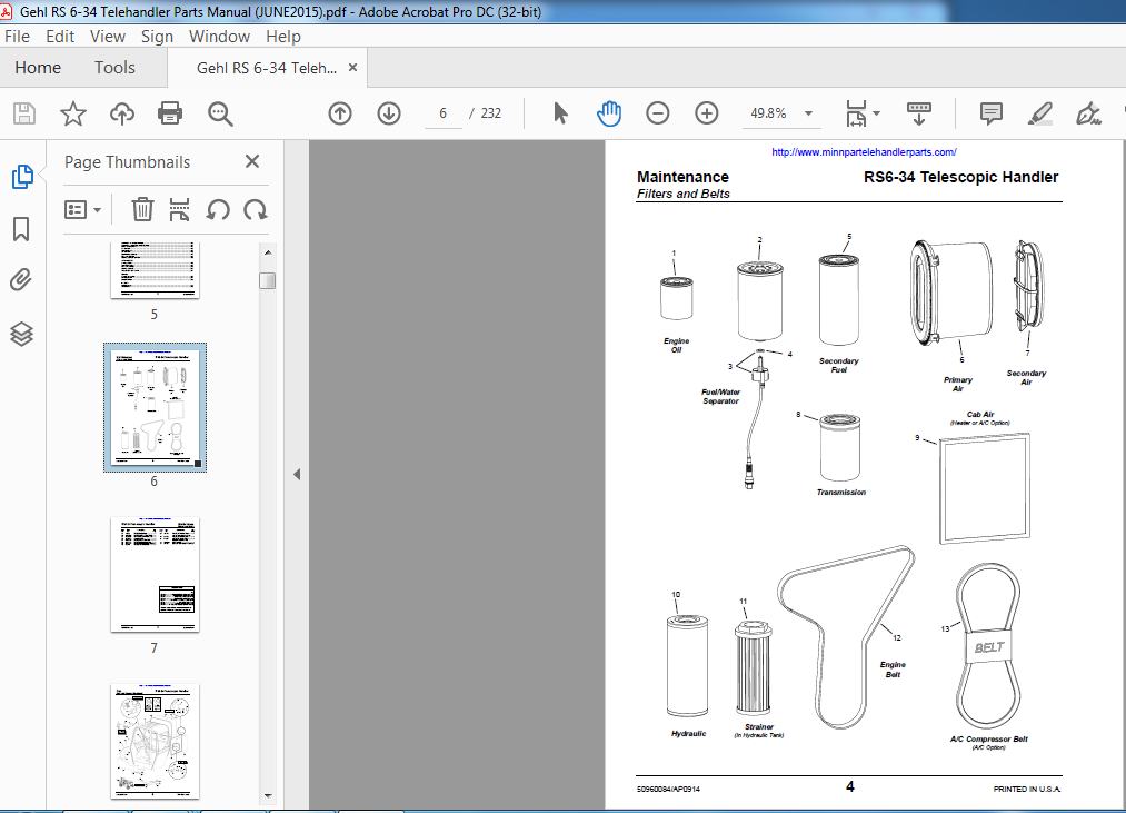
Filters and Belts
CAB
Cab and Covers (Standard)
Cab Mounts
Front Work Lights and Strobe Light (Option)
Glass – Front and Rear Window Group (Option)
Wipers
Glass – Top and Left Window (Option)
Door
Instruments, Switches and Fuses
Fuses, Relays, and Modules
Seat
Steering Column and Shifter Group
Steer Motor and Steer Select Valve Group
Brake and Accelerator Pedals
Brake Valve Hydraulic Circuit
Cab Components – Tri-Function Controls (Option)
Heater (Option) – (No A/C)
A/C – Heater – (A/C – Option)
A/C Circuit (Option)
Heater Circuit (Option)
A/C Condenser – (A/C Equipped – Option)
CHASSIS
Hoods – Front
Hoods – Center
Hoods and Covers – Rear
Hydraulic Tank Group
Fuel Tank Group
Battery Group and ECU
Frame Level Circuit
PERSONNEL WORK PLATFORM
Boom Components – (Standard PWP)
Level Sensor, Module, Chains, and Manifold (for Standard and Radio Remote)
PWP Radio Remote (Option) – Transmitter and Receiver
ENGINE
External Components
A/C Compressor Group – (Option)
Fuel Circuit
Radiator and Cooler Group
Radiator and Cooler Components
Air Intake Group
Exhaust Group
TRANSMISSION
External Components (including driveshafts)
Drive (Flex) Plate Group
Converter Housing Group
Case and Plate Group
Torque Converter Group
Gear Group
Drive Pump Group
Charge Pump Group
Output Shaft Group
Reverse Idler Group
Forward and Reverse Group
Third Shaft Group
First and Second Shaft Group
Modulation Valve Group
Control Group
AXLE
External Components
Brake and Steering Circuit – Front Axle
Brake and Steering Circuit – Rear Axle
Front Axle – Steer Cylinder and Tie Rods Group
Rear Axle – Steer Cylinder and Tie Rods Group
Front Axle – Differential Housing Group
Rear Axle – Differential Housing Group
Front Axle – Brake Group
Rear Axle – Brake Group
Front Axle – Outer End Group
Front Axle – Differential Group
Rear Axle – Outer End Group
Rear Axle – Differential Group
BOOM
Outer Boom Section
Intermediate Boom Section
Inner Boom Section
Dynattach Bracket Assembly
BOOM HYDRAULICS
Lift Circuit
Tilt / Slave Circuit
Boom Extend Circuit
Auxiliary Hydraulics Circuit
HYDRAULIC SYSTEMS
Hydraulic Pump Group
Hydraulic Control Valve and Hoses
Dual Controls Circuit (Standard) Circuit
Tri-Function Control (Option) – Standard Hydraulics Circuit
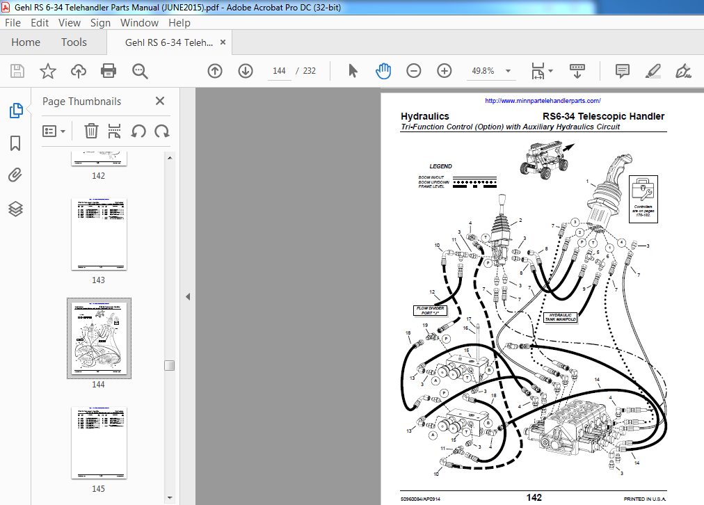
Tri-Function Control (Option) and Auxiliary Hydraulics Circuit
Table of Contents RS- Telescopic Handler
http://wwwminnpartelehandlerpartscom/
PRINTED IN USA /AP
Page
Radio Remote (Option) Circuit
Dual Controls – Standard
Dual Controls with only Auxiliary Hydraulics (Option)
Dual Controls with only PWP (Option)
Dual Controls with PWP and Auxiliary Hydraulics (Option)
Dual Controls with Radio Remote (Option)
Dual Controls with Radio Remote and Auxiliary Hydraulics (Option)
Tri-Function Control (Option) with only PWP
Tri-Function Control (Option) with PWP and Auxiliary Hydraulics
Tri-Function Control (Option) with Radio Remote
Tri-Function Control (Option) with Radio Remote and Auxiliary Hydraulics
HYDRAULIC COMPONENTS
Hydraulic Pump
Joystick Relief – Flow Divider
Hydraulic Control Valve (including auxiliary hydraulics work section)
PWP Valve
Steer Select Valve
Steer Motor
Brake Valve
Pilot Apply Manifold – Tri-Function Controller (Option)
Radio Remote (Option) Manifold
Controller – Tilt/Frame Level
Controller – Lift/Extend
Controller – Tri-Function (Option)
Controller – Auxiliary Hydraulics (Option)
Frame Level Cylinder
Lift Cylinder
Slave Cylinder
Tilt Cylinder
Boom-Extend Cylinder
Fork-Shift Cylinder
Rotating-Carriage Cylinder
ATTACHMENTS
Carriage Forks
Standard Carriage
Fork-Shift Carriage
Rotating Carriage
Truss Booms and Bucket
DECALS
General Information
New Application
Decal Locations
INDEXES
Numeric Index
Subject Index
VIDEO PREVIEW OF THE MANUAL:

IMAGES PREVIEW OF THE MANUAL:
PLEASE NOTE:
- This is not a physical manual but a digital manual – meaning no physical copy will be couriered to you. The manual can be yours in the next 2 mins as once you make the payment, you will be directed to the download page IMMEDIATELY.
- This is the same manual used by the dealers inorder to diagnose your vehicle of its faults.
- Require some other service manual or have any queries: please WRITE to us at [email protected]


