FURUKAWA UNIC UR SERIES UR220 UR250 UR260 UR290 UR330 UR360 UR500 HYDRAULIC CRANE WORKSHOP MANUAL PDF
$25.95
FURUKAWA UNIC UR SERIES UR220 UR250 UR260 UR290 UR330 UR360 UR500 HYDRAULIC CRANE WORKSHOP MANUAL PDF
Description
FURUKAWA UNIC UR SERIES UR220 UR250 UR260 UR290 UR330 UR360 UR500 HYDRAULIC CRANE WORKSHOP MANUAL PDF
FILE DETAILS:
FURUKAWA UNIC UR SERIES UR220 UR250 UR260 UR290 UR330 UR360 UR500 HYDRAULIC CRANE WORKSHOP MANUAL PDF
Language : English
Pages : 119
Downloadable : Yes
File Type : PDF
IMAGES PREVIEW OF THE MANUAL:
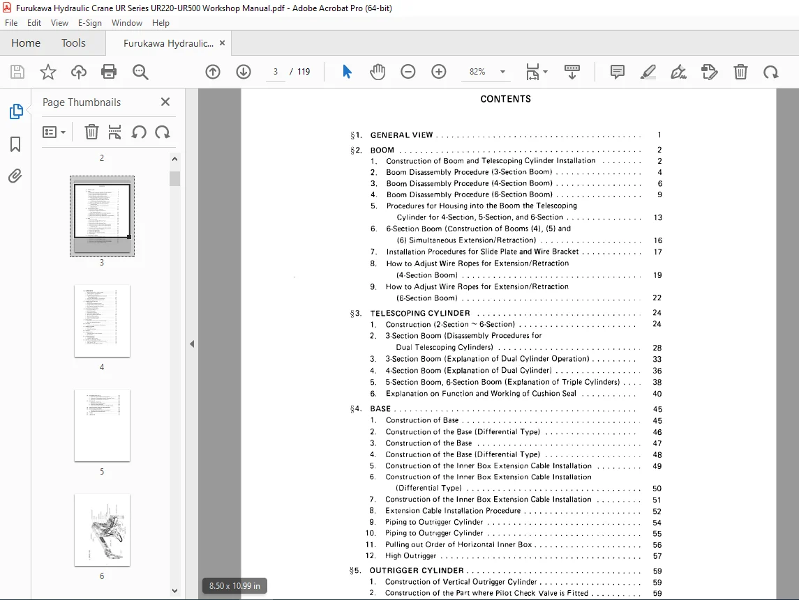
TABLE OF CONTENTS:
FURUKAWA UNIC UR SERIES UR220 UR250 UR260 UR290 UR330 UR360 UR500 HYDRAULIC CRANE WORKSHOP MANUAL PDF
GENERAL VIEW . …… .
BOOM …………… . 2
1. Construction of Boom and Telescoping Cylinder Installation . . . . . . . 2
2. Boom Disassembly Procedure (3-Section Boom) . . . . . . . . . . . . . . . . . 4
3. Boom Disassembly Procedure (4-Section Boom) . . . . . . . . . . . . . . . . . 6
4. Boom Disassembly Procedure (6-Section Boom) . . . . . . . . . . . . . . . . . 9
5. Procedures for Housing into the Boom the Telescoping
Cylinder for 4-Secti,on, 5-Section, and 6-Section . . . . . . . . . . . . . . . 13
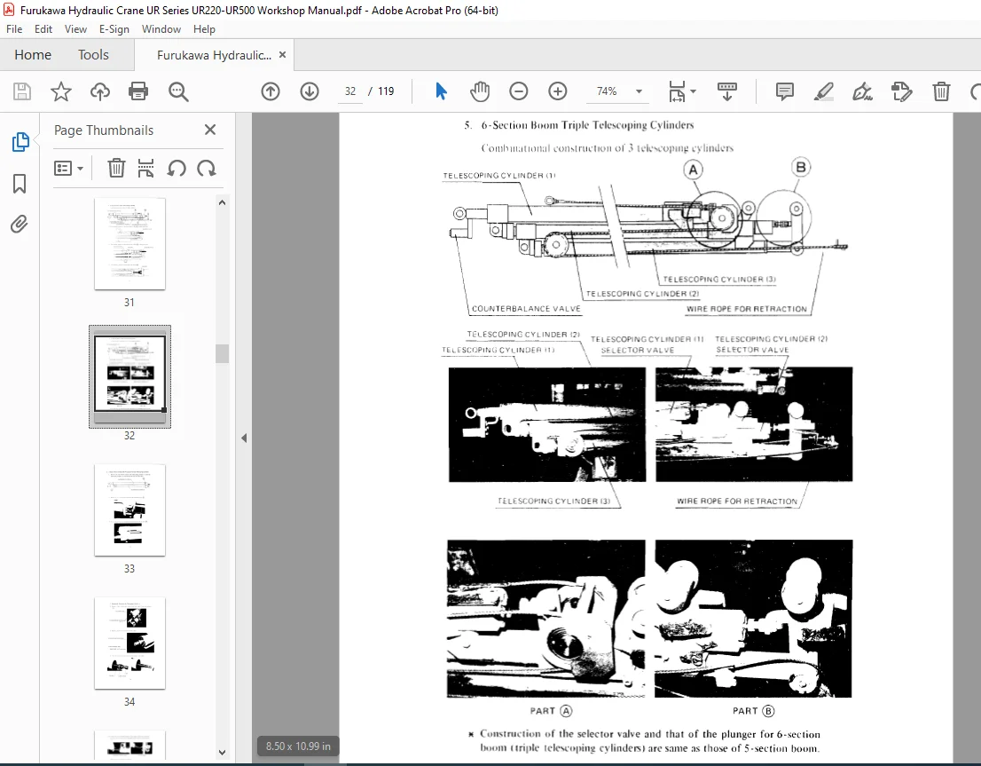
6. 6-Section Boom (Construction of Booms (4), (5) and
(6) Simultaneous Extension/Retraction) . . . . . . . . . . . . . . . . . . . . 16
7. Installatiion Procedures for SI ide Plate and Wire Bracket . . . . . . . . . . . . 17
8. How to Adjust Wire Ropes for Extension/Retraction
(4-Section Boom) . . . . . . . . . . . . . . . . . . . . . . . . . . . . . . . . . . 19
9. How to Adjust Wire Ropes for Extension/Retraction
(6-Section Boom) . . . . . . . . . . . . . . . . . . . . . . . . . . . . . . . . . . 22
§3. TELESCOPING CYLINDER . . . . . . . . . . . . . . . . . . . . . . . . . . . . . . . 24
§4.
1. Construction (2-Section ~ 6-Section) . . . . . . . . . . . . . . . . . . . . . . . 24
2. 3-Section Boom (Disassembly Procedures for
Dual Telescoping Cylinders) . . . . . . . . . . . . . . . . . . . . . . . . . . . . 28
3. 3-Section Boom (Explanation of Dual Cylinder Operation) . . . . . . . . . 33
4. 4-Section Boom (Explanation of Dual Cylinder) . . . . . . . . . . . . . . . . . 36
5. 5-Section Boom, 6-Section Boom (Explanation of Triple Cvlinders) . . . 38
6. Explanation on Function and Working of Cushion Seal . . . . . . . . . . . 40
BASE ….
1.Construction of Base …………………………… .45
2.Construction of the Base ( Differential Type) …………….. 45
3.Construction of the Base …………………………. 46
4.Construction of the Base (Differential Type) ……………… 47
5.Construction of the Inner Box Extension Cable Installation…………48
6. Construction of the Inner Box Extension Cable Installation………….49
(Differential Type) . . . . . . . . . . . . . . . . . . . . . . . . . . . . . . . . . . 50
7. Construction of the Inner Box Extension Cable Installation . . . . . . . . . 51
8. Extension Cable Installation Procedure . . . . . . . . . . . . . . . . . . . . . . . 52
9. Piping to Outrigger Cylinder . . . . . . . . . . . . . . . . . . . . . . . . . . . . . . 54
10. Piping to Outrigger Cylinder . . . . . . . . . . . . . . . . . . . . . . . . . . . . . . 55
11. Pulling out Order of Horizontal Inner Box. . . . . . . . . . . . . . . . . . . . . 56
12. High Outrigger . . . . . . . . . . . . . . . . . . . . . . . . . . . . . . . . . . . . . . . 57
§5. OUTRIGGER CYLINDER . . . . . . . . . . . . . . . . . . . . . . . . . . . . . . . . . . 59
1. Construction of Vertical Outrigger Cylinder . . . . . . . . . . . . . . . . . . . . 59
2.Construction of the Part where Pilot Check Valve is Fitted ……… .59
3.Construction of Vertical Outrigger Cylinder ………………. .60
4.Construction of the Part where Pilot Check Valve is Fitted ……… .60
5.Construction of Vertical Outrigger Cylinder (High Outrigger) ……. .61
6.Construction of Horizontal Outrigger Cylinder …….. ..62
§6. SLEWING DEVICE . . . . . . . . . . . . . . . . . . . . . . . . . . . . . . . . . . . . . . 63
1. Position of Soft Zone “S” on the Turntable . . . . . . . . . . . . . . . . . . . . 63
2. Tightening Order of Turntable Bolts. . . . . . . . . . . . . . . . . . . . . . . . . 6:3
3. Turntable Mounting Procedure . . . . . . . . . . . . . . . . . . . . . . . . . . . . 64
4. Tightening Torque for Bolts Fastening Turntable and
5. Slewing Reduction Gear ………………. , ………. .66
6. Numerical Tightening Order of Turntable Bolts……….67
7. Tightening Torque for Bolts Fastening Column ……………. .68
§7. SLEWING REDUCTION GEAR 69
1 . Construction . . . . . . . . . . . . . . . . . . . . . . . . . . . . . . . . . . . . . . . . 69
2. Reduction Gear Disassembly Procedure . . . . . . . . . . . . . . . . . . . . . . 70
3. Precaution When Assembling Reduction Gear . . . . . . . . . . . . . . . . . . 74
4. Bolt Tightening Torque for Bearing Housing . . . . . . . . . . . . . . . . . . . 75
5. Gear Oil for Reduction Gear . . . . . . . . . . . . . . . . . . . . . . . . . . . . . . 75
§8. HOIST WINCH (SI LENT WINCH) . . . . . . . . . . . . . . . . . . . . . . . . . . . . . 76
1. Construction of Winch . . . . . . . . . . . . . . . . . . . . . . . . . . . . . . . . . . 76
2. Construction of Brake . . . . . . . . . . . . . . . . . . . . . . . . . . . . . . . . . . 76
3. Explanation of Operation . , . . . . . . . . . . . . . . . . . . . . . . . . . . . . . . 77
4. Construction of Reduction Gear . . . . . . . . . . . . . . . . . . . . . . . . . . . 78
5. Bolt Fastening Reduction Gear Casing . . . . . . . . . . . . . . . . . . . . . . . 80
6. Gear Oil for Reduction Gear . . . . . . . . . . . . . . . . . . . . . . . . . . . . . . 81
7. Brake Shoe Adjusting Procedure . . . . . . . . . . . . . . . . . . . . . . . . . . . 81
8. Cause of Troubles and Remedy . . . . . . . . . . . . . . . . . . . . . . . . . . . . 82
§9 SWIVEL JOINT . . . . . . . . . . . . . . . . . . . . . . . . . . . . . . . . . . . . . . . . . 8:1
1. Construction of Swivel Joint and Positions of Hoses . . . . . . . . . . . . . . 8:1
2. Swivel Joint Assembling Procedure …………. , . . . . . . . . . . . 85
§10. SLIP RING . . . . . . . . . . . . . . . . . . . . . . . . . . . . . . . . . . . . . . . . . . . . 86
§ 11.
1. Construction of Slip Ring and Its Fitting Position . . . . .. . . . . . . . . . . . 86
DERRICK CYLINDER …………………… .87
1. Construction ……… .87
2. Disassembling Procedure ……………….. .87
§ 12. CONTROL . . . . . . . . . . . . . . . . . . . . . . . . . . . . . . . . . . . . . . . . . . . . 88
§13. ALARM SYSTEM ………. . 90
1. Push-button Switch Installing Procedure ………………… .91
2. Wiring Diagram ………. .91
§14. HYDRAULIC CIRCUIT . . . . . . . . . . . . . . . . . . . . . . . . . . . . . . . . . . . 92
1. LI R Series Standard . . . . . . . . . . . . . . . . . . . . . . . . . . . . . . . . . . . . 92
2. URH Series (High Outrigger)… . . . . . . . . . . . . . . . . . . . . . . . . . . . 93
§15. CONTROL VALVE (MODEL: MV-30A) . . . . . . . . . . . . . . . . . . . . . . . . 95
1. Composition of Valves and Inscribed Mark on Spool . . . . . . . . . . . . . . 95
2. ReliefValve(RT-15C) ……………………………. 96
3. Explanation of Meter-in/Meter-out Spool . . . . . . . . . . . . . . . . . . . . . 97
§16. COUNTERBALANCE VALVE . . . . . . . . . . . . . . . . . . . . . . . . . . . . . . . 100
·1. Construction of Counterbalance Valve (for Derrick) . . . . . . . . . . . . . . 100
:2. Construction of Counterbalance Valve (for Telescoping Cylinder) . . . . . 100
3. Explanation of Counterbalance Valve Operation . . . . . . . . . . . . . . . . . 101
§17. DI-CO VALVE . . . . . . . . . . . . . . . . . . . . . . . . . . . . . . . . . . . . . . . . . 103
‘I. Construction of DI-CO Valve . . . . . . . . . . . . . . . . . . . . . . . . . . . . . 103
:i. Explanation of DI-CO Valve Operation. . . . . . . . . . . . . . . . . . . . . . . 104
:3. DI-CO Valve Handling Precautions. . . . . . . . . . . . . . . . . . . . . . . . . . 105
4. Failure in the Synchronized Operation of Outrigger Cylinders. . . . . . . . 106
§18. CONSTRUCTION OF HOOK (FOR 6-SECTION BOOM). . . . . . . . . . . . . . 107
§19. HOW TO HANDLE WIRE ROPES . . . . . . . . . . . . . . . . . . . . . . . . . . . . . 108
·1. Passing Wire Rope into Wire Socket and Fastening It . . . . . . . . . . . . . . 108
:2. Twisted Wire Rope Adjusting Procedure . . . . . . . . . . . . . . . . . . . . . . 108
§20. FILTERS ……………………………………… 109
§21. !LUBRICATION ………………………………….. 110
Need help? Contact: [email protected]
https://vimeo.com/846507235?share=copy
DESCRIPTION:
FURUKAWA UNIC UR SERIES UR220 UR250 UR260 UR290 UR330 UR360 UR500 HYDRAULIC CRANE WORKSHOP MANUAL PDF
INTRODUCTION:
This technical instruction manual describes the constructic,n of the UR truck cranes and maintenance procedures for the servicemen engaged in their maintenance.
- Please carefully read the manual to acquire the proper maintenance skills and provide efficient, speedy, correct services that are ,essential to customer trust.
- In this way, UNIC truck cranes will bei able to deliver their superb pe11ormance and be kept in satisfactory operating condition. It is recommended that the separate parts list be referred to together with this manual.
PLEASE NOTE:
- This is the same manual used by the dealers to diagnose and troubleshoot your vehicle
- You will be directed to the download page as soon as the purchase is completed. The whole payment and downloading process will take anywhere between 2-5 minutes
- Need any other service / repair / parts manual, please feel free to contact [email protected] . We still have 50,000 manuals unlisted
G.P