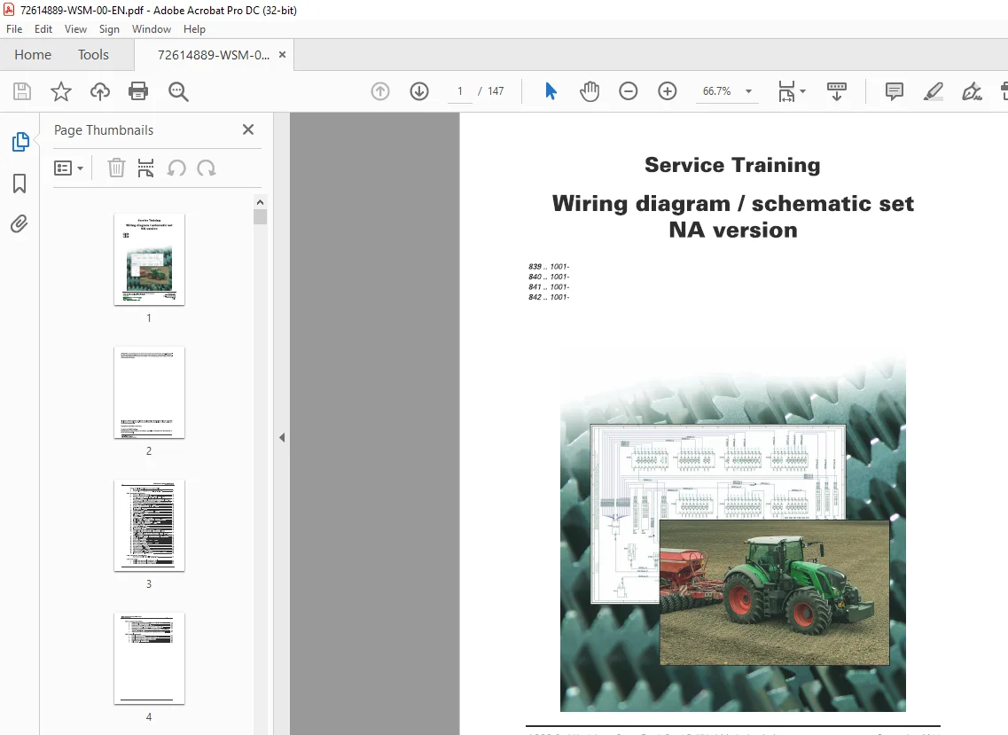
Fendt NA 839 840 841 842 Wiring diagram schematic set Service Training Manual
$25.95
Fendt NA 839 840 841 842 Wiring diagram schematic set Service Training Manual – PDF DOWNLOAD
Description
Fendt NA 839 840 841 842 Wiring diagram schematic set Service Training Manual – PDF DOWNLOAD
FILE DETAILS:
Fendt NA 839 840 841 842 Wiring diagram schematic set Service Training Manual – PDF DOWNLOAD
Language : English,
Pages :147
Downloadable : Yes
File Type : PDF
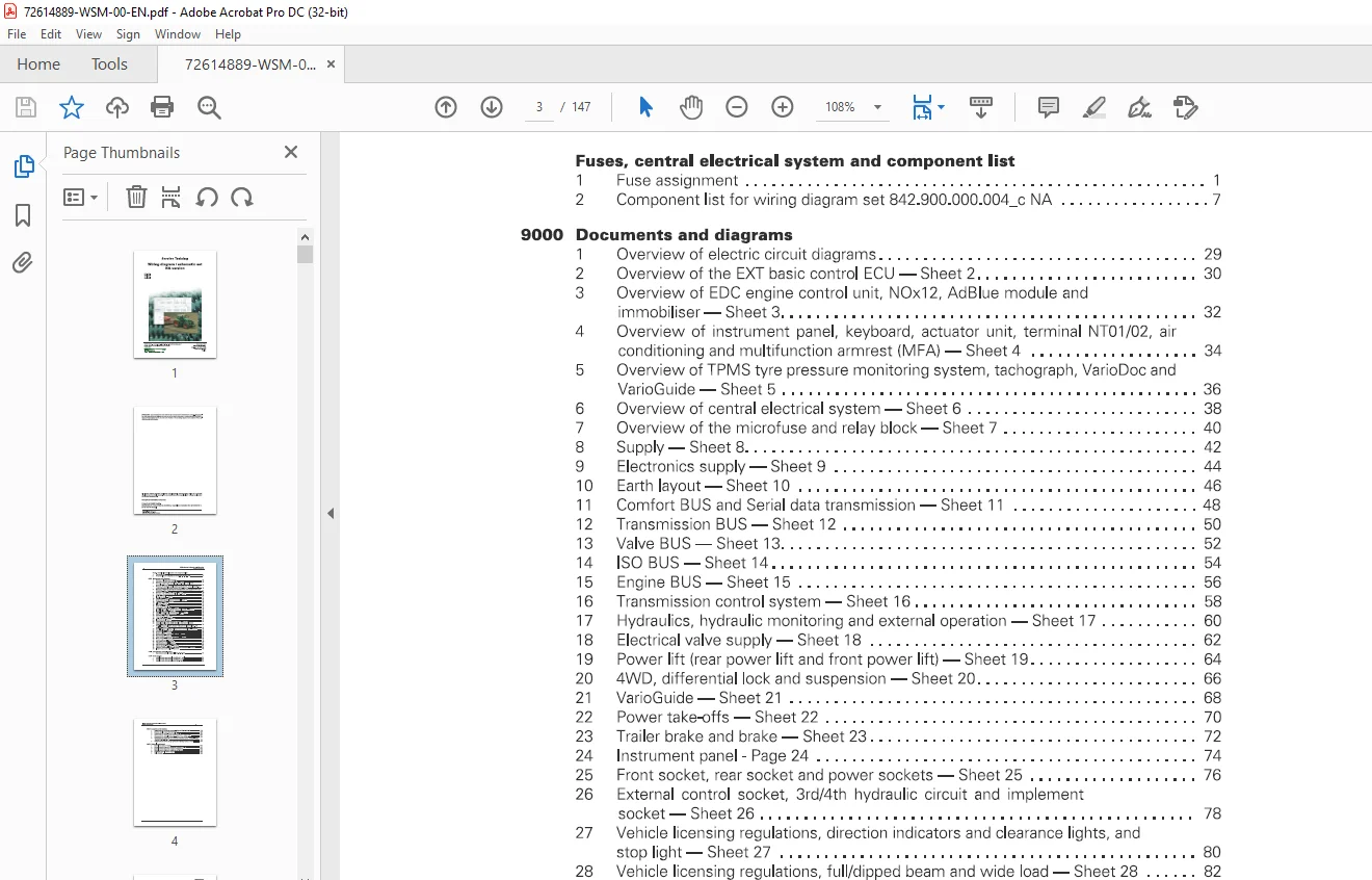
TABLE OF CONTENTS:
Fendt NA 839 840 841 842 Wiring diagram schematic set Service Training Manual – PDF DOWNLOAD
Fuses, central electrical system and component list
1 Fuse assignment
2 Component list for wiring diagram set 842900000004_c NA 7
9000 Documents and diagrams
1 Overview of electric circuit diagrams 29
2 Overview of the EXT basic control ECU – Sheet 2 30
3 Overview of EDC engine control unit, NOx12, Ad Blue module and
immobiliser – Sheet 3 32
4 Overview of instrument panel, keyboard, actuator unit, terminal NT01/02, air
conditioning and multifunction armrest (MFA) – Sheet 4 34
5 Overview of TPMS tyre pressure monitoring system, tachograph, VarioDoc and
VarioGuide – Sheet 5 36
6 Overview of central electrical system – Sheet 6 38
7 Overview of the microfuse and relay block – Sheet 7 40
8 Supply – Sheet 8 42
9 Electronics supply – Sheet 9 44
10 Earth layout – Sheet 10 46
11 Comfort BUS and Serial data transmission – Sheet 11 48
12 Transmission BUS – Sheet 12 50
13 Valve BUS – Sheet 13 52
14 ISO BUS-Sheet 14 54
15 Engine BUS – Sheet 15 56
16 Transmission control system – Sheet 16 58
17 Hydraulics, hydraulic monitoring and external operation – Sheet 17 60
18 Electrical valve supply – Sheet 18 62
19 Power lift (rear power lift and front power lift) – Sheet 19 64
20 4WD, differential lock and suspension – Sheet 20 66
21 VarioGuide – Sheet 21 68
22 Power take-offs – Sheet 22 70
23 Trailer brake and brake – Sheet 23 72
24 Instrument panel – Page 24 74
25 Front socket, rear socket and power sockets – Sheet 25 76
26 External control socket, 3rd/4th hydraulic circuit and implement
socket – Sheet 26 78
27 Vehicle licensing regulations, direction indicators and clearance lights, and
stop light – Sheet 27 80
28 Vehicle licensing regulations, full/dipped beam and wide load – Sheet 28 82
29 Front work light – Sheet 29 84
30 Rear work light – Sheet 30 86
31 Reverse operation, seat and cab lighting – Sheet 31 88
32 Air conditioning – Sheet 32 90
33 Wiper, window heating and rotary beacon – Sheet 33 92
34 Mirror and radio – Sheet 34 94
35 Camera equipment- Sheet 35 96
36 EDC engine control – Sheet 36 98
37 DE UTZ engine control – Sheet 37 100
38 DE UTZ engine control 2 – Sheet 38 102
39 Exhaust gas after-treatment – Sheet 39 104
40 VarioDoc, GNNS aerial, VarioGuide GNNS and tachograph – Sheet 40 106
41 Indicator and reserve cables – Sheet 41 108
1005 Transmission control system
1 Transmission hydraulic diagram – 842100000002 110
1070 Brake system
1 Hydraulic brake system: single circuit brake, 1 pedal 112
2 Hydraulic brake system: single circuit brake, 2 pedals 114
3 Hydraulic brake system: dual circuit brake, 1 pedal 116
Wiring diagram I schematic set- NA version
Table of contents
8800 Compressed air system
1 Compressed air monitoring system – diagram 842880000001 118
2 Pressure supply compressed air system 120
3 Compressed air system, circuit 3 trailer supply 122
4 Compressed air system, circuit 4 cab suspension + engine brake 124
5 Compressed air system, 4th circuit – reverse drive function 126
6 Compressed air system for tyre pressure monitoring system (TPMS) – wiring
diagram 842880200001 128
7 Compressed air system for tyre pressure monitoring system (TPMS) 130
9600 Hydraulic equipment
1 Hydraulic equipment diagram 132
2 Hydraulic circuit diagram for maximum number of valves 134
3 Hydraulic circuit diagram for medium configuration 136
4 Hydraulic circuit diagram for minimum configuration 138
5 VarioGuide hydraulic circuit diagram 140
6 Valve sections 142
IMAGES PREVIEW OF THE MANUAL:
S.M 7/24