FENDT 900 927 930 933 936 939 Vario S4 Workshop Service Manual
$35.95
FENDT 900 927 930 933 936 939 Vario S4 Workshop Service Manual – PDF DOWNWLOAD
950 .. 1001-
950 .. 1001-
952 .. 1001-
953 .. 1001-
954 .. 1001-
Description
FENDT 900 927 930 933 936 939 Vario S4 Workshop Service Manual – PDF DOWNWLOAD
FILE DETAILS:
FENDT 900 927 930 933 936 939 Vario S4 Workshop Service Manual – PDF DOWNWLOAD
Language : English
Pages :1032
Downloadable : Yes
File Type : PDF
950 .. 1001-
950 .. 1001-
952 .. 1001-
953 .. 1001-
954 .. 1001-
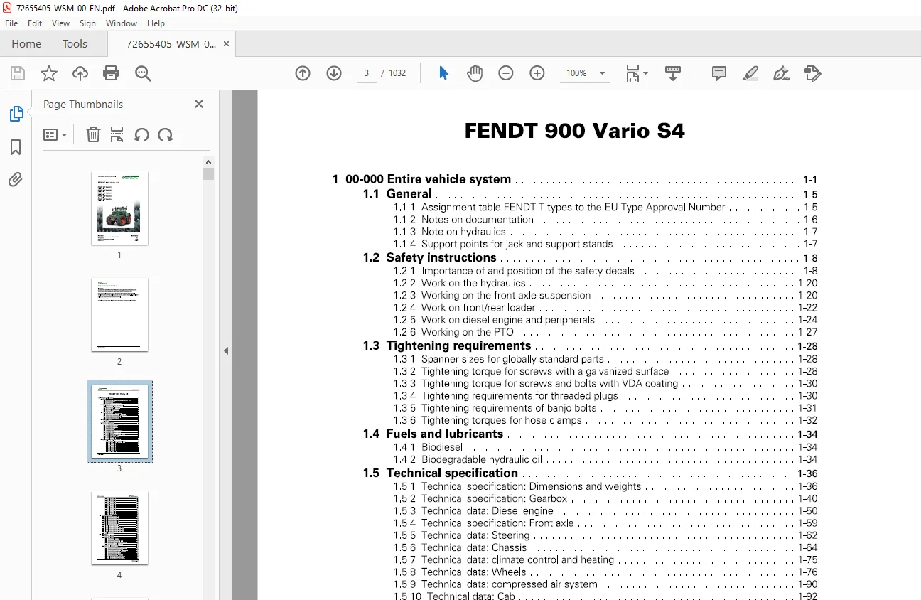
TABLE OF CONTENTS:
FENDT 900 927 930 933 936 939 Vario S4 Workshop Service Manual – PDF DOWNWLOAD
1 00-000 Entire vehicle system 1-1
11 General 1-5
111 Assignment table FENDT T types to the EU Type Approval Number 1-5
1 12 Notes on documentation 1-6
113 Note on hydraulics 1-7
1 14 Support points for jack and support stands 1-7
12 Safety instructions 1-8
121 Importance of and position of the safety decals 1-8
1 22 Work on the hydraulics 1-20
1 23 Working on the front axle suspension 1-20
1 24 Work on front/rear loader 1-22
125 Work on diesel engine and peripherals 1-24
126 Working on the PTO 1-27
13 Tightening requirements 1-28
1 31 Spanner sizes for globally standard parts 1-28
132 Tightening torque for screws with a galvanized surface 1-28
133 Tightening torque for screws and bolts with VDA coating 1-30
134 Tightening requirements for threaded plugs 1-30
135 Tightening requirements of banjo bolts 1-31
136 Tightening torques for hose clamps 1-32
14 Fuels and lubricants 1-34
1 41 Biodiesel 1-34
142 Biodegradable hydraulic oil 1-34
15 Technical specification 1-36
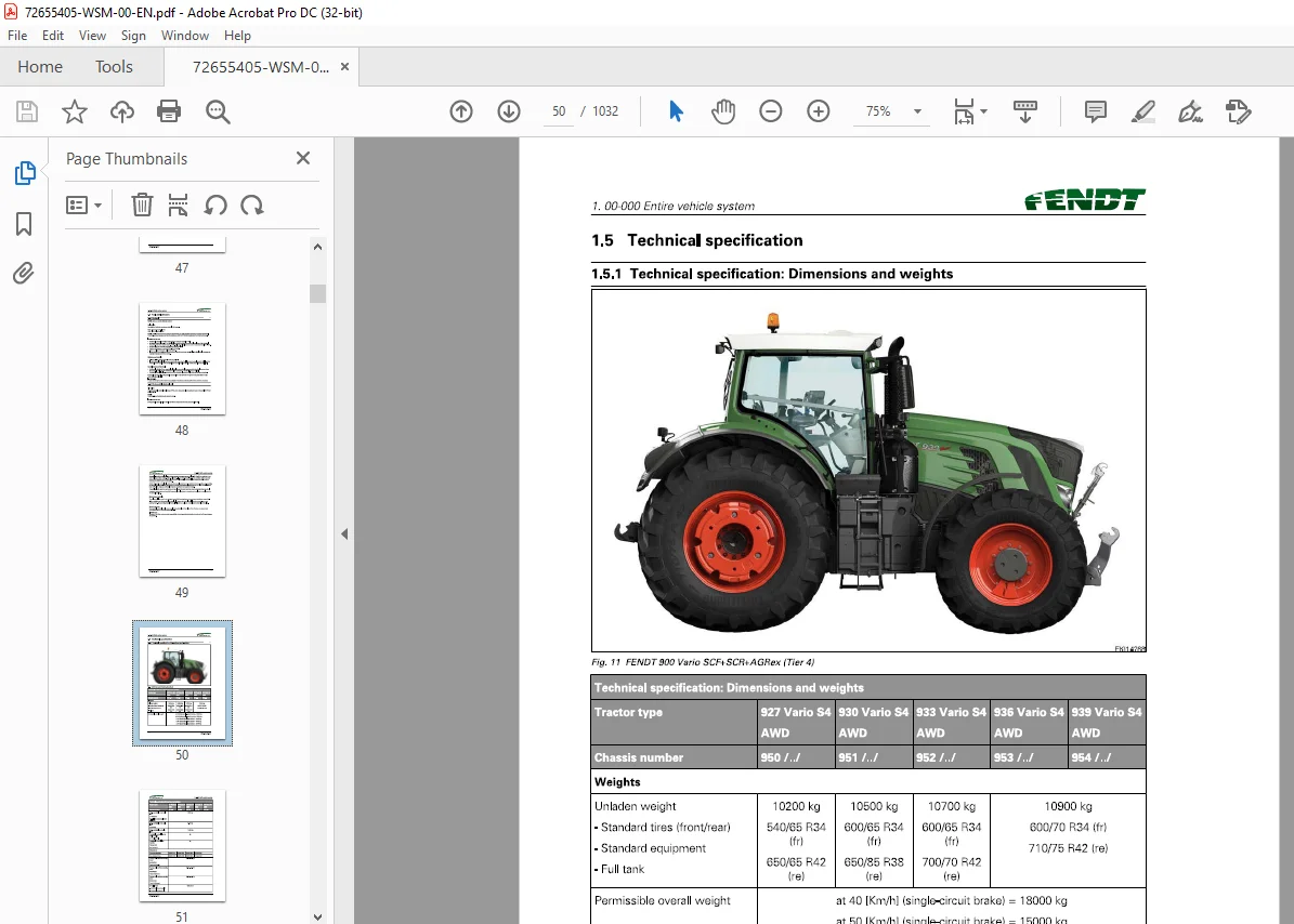
151 Technical specification: Dimensions and weights 1-36
152 Technical specification: Gearbox 1-40
153 Technical data: Diesel engine 1-50
154 Technical specification: Front axle 1-59
155 Technical data: Steering 1-62
156 Technical data: Chassis 1-64
157 Technical data: climate control and heating 1-75
158 Technical data: Wheels 1-76
159 Technical data: compressed air system 1-90
1510 Technical data: Cab 1-92
1511 Technical data: Three-point linkage and lift system 1-92
1512 Technical data: Front/rear loader 1-94
1513 Technical data: Electrical system 1-97
1514 Technical data: Hydraulics 1-98
16 Fault code tables 800 / 900 Vario S4 2-1
161 Fault code tables 2-3
FENDT 900 Vario S4
X990005531 013
1611 Confirming, calling up, deleting fault codes 2-3
1612 Fault code 00000 2-5
1613 Fault code 01 000 2-9
1614 Error code 02100 2-16
1615 Error code 03100 2-18
1616 Fault code 04100 2-20
161 7 Fault code 05100 2-33
1618 Fault code 06100 2-38
1619 Fault code 07 100 2-43
16110 Fault code 08100 2-45
Table of contents
16111 Fault code 09100 2-51
16112 Fault code 0A1 00 2-56
16113 Fault code 0B100 2-75
16114 Error code 0D100 2-78
16115 Fault code 0E100 2-81
16116 Error code 0F100 2-86
16117 Fault code 10100 2-90
16118 Error code 12100 2-91
16119 Fault code 15100 2-99
16120 Fault code 17100 2-100
16121 Fault code 1801 00 2-101
16122 Fault code 1 A1 00 2-104
16123 Fault code 1 D100 2-109
16124 Fault code 1 F100 2-121
16125 Error code 20100 2-122
16126 Calibration fault codes 2-127
17 Component position 1-137
1 7 1 Electrical/electronic components – A 1-137
1 7 2 Electrical/electronic components – B 1-147
1 7 3 Electrical/electronic components – E 1-162
1 74 Electrical/electronic components – F 1-173
175 Electrical/electronic components – G 1-173
1 7 6 Electrical/electronic components – H 1-17 4
1 7 7 Electrical/electronic components – K 1-176
1 7 8 Electrical/electronic components – M 1-179
1 7 9 Electrical/electronic components – R 1-183
1 7 10 Electrical/electronic components – S 1-184
1 7 11 Electrical/electronic components – U 1-192
1712 Electrical/electronic components – X (0001-1000) 1-193
1713 Electrical/electronic components – X (1001-2000) 1-197
1714 Electrical/electronic components – X (2001-4000) 1-202
1715 Electrical/electronic components-X (4001-6000) 1-203
1 7 16 Electrical/electronic components – Y 1-239
1 7 17 Hydraulic components 1-251
18 Calibrations 1-292
181 Adjustments – General 1-292
1 811 Calibration notes 1-292
182 Adjustments – Gearbox 1-292
1821 Calibration 4001 clutch pedal 1-292
1822 Calibration 4002: Hand throttle 1-295
1823 Calibration 4003: Travel range selector 1-298
1824 Calibration 4005 driving pedal 1-302
1825 Calibration 4007: Transmission ratio characteristic 1-304
1826 Calibration 4009: Turbo-clutch function 1-308
1827 Calibration 4010 driving pedal resolution 1-312
183 Adjustments – Sensors and functions 1-315
1831 Calibration 1001 crossgate lever 1-315
1832 Calibration 1003/1004/1005/1006 Linear modules 1-321
1833 Calibration 2401 steering angle sensor 1-325
1834 Calibration 2401 – checking the calibration accuracy 1-329
1835 Calibration 2403: Steering valve, when required 1-331
1836 Calibration 6034: Rear PTO clutch 1-335
1837 Calibration 7034 front PTO clutch 1-338
1 838 Calibration 7666: Front axle suspension 1-341
1839 Calibration 8001 rear EPC – depth control 1-344
18310 Calibration 8002: Rear EPC – position control 1-347
18311 Calibration 9001 front EPC – depth control 1-351
18312 Calibration 9002 front EPC – position control 1-354
FENDT 900 Vario S4
X990 005531013
Table of contents
18313 Heating valve calibration – automatic air-conditioning system 1-357
18314 Speed display calibration 1-359
19 Calibrations fault code 1-362
1 91 Calibration fault code 1001 1-362
1 92 Calibration fault code 1003 1-362
1 93 Calibration fault code 1004 1-362
1 94 Calibration fault code 1005 1-363
195 Calibration fault code 1006 1-363
196 Calibration fault code 2401 1-363
197 Calibration fault code 2403 1-364
1 98 Calibration fault code 4001 1-364
199 Calibration fault code 4002 1-365
1 910 Calibration fault code 4003 1-365
1 911 Calibration fault code 4005 1-366
1 912 Calibration fault code 4007 1-366
1 913 Calibration fault code 4009 1-368
1914 Calibration fault code 4010 1-369
1 915 Calibration fault code 7666 1-370
1916 Calibration fault code 8001 1-370
1 917 Calibration fault code 8020 1-370
1 918 Calibration fault code 8021 1-371
1919 Calibration fault code 8022 1-371
1920 Calibration fault code 8023 1-371
1921 Calibration fault code 9001 1-372
1 922 Calibration fault code 9002 1-372
1923 Tire circumference calibration fault code 1-372
1 924 Heater valve calibration fault code 1-372
3 01-000 Engine, fuel and exhaust system 3-1
31 General 3-3
311 Engine horsepower: comparison of standards and directives 3-3
312 General description of the common rail system 3-4
313 PTO power measurement 3-5
32 motor 3-8
321 Faults 3-8
322 Read out the Trip Recorder (load spectrum) using Serdia diagnostics 3-19
323 Automatic calibration of injectors ZFL 3-26
324 Deutz TCD 61/78 engines: Read out fault memory 3-34
325 Calculating the fuel consumption of a diesel engine 3-45
326 Ad Blue® – and fuel consumption (emission level 4, Tier 4f) 3-53
327 Compression test with SerDia 3-58
328 Compression test with compression pressure recorder 3-62
329 Crankcase pressure and ventilation 3-68
3210 Remove and replace the belt drive and tension pulley; repair the tension pulley 3-75
33 Cylinder head 3-86
331 Valve adjustment (Deutz and AGCO Power engines) 3-86
332 Remove and install the injector and injector sleeve 3-101
34 Cooling system 3-128
341 Coolant circuit: Deutz TTCD 7 8 3-128
35 Fuel system 3-136
351 Pressure testing common rail system / fuel pre-filter / injector / dispensing unit /
high-pressure pump 3-136
352 High-pressure accumulator: Common rail 3-180
353 Design and function of the high-pressure relief valve 3-181
354 High-pressure relief valve and rail pressure sensor: removal and installation 3-182
355 Y095 to Y101 – Injectors 1 to 6 3-186
36 Lubrication 3-190
FENDT 900 Vario S4
X990005531 013
Table of contents
361 Schema: engine lubrication Deutz TTCD 7 8 L6 4V 3-190
37 Charge air and exhaust gas system 3-196
371 Design, operating conditions and cleaning 3-196
372 Fault analysis on exhaust gas return (AG Rex) 3-222
373 Function test of exhaust gas after-treatment system (DPF/SCR) with Serdia
diagnostics program 3-229
374 Diesel particulate filter: Active regeneration and filter replacement 3-234
375 Decrystallization of the SCR exhaust system 3-243
376 Fault analysis on A084 supply module/Y120 AdBlue flow valve (read faults/flush/
check SCR system) 3-253
377 SCR heater fault analysis 3-286
4 02-000 Front axle 4-1
41 Front axle 4-3
411 Technical drawing: Wishbone arm 4-3
412 Technical drawing: Planetary final drive and steering knuckle housing 4-9
413 Technical drawing: Suspension cylinder 4-13
414 Technical drawing: Pinion shaft and differential 4-15
415 Axle shaft with/without brake 4-20
416 Removing front axle 4-26
417 Disassemble and reassemble ZF suspension cylinder/ replace mounting pins 4-30
418 Check play in the front axle drive shaft 4-55
42 Suspension 4-64
421 Functional diagrams of front axle suspension 4-64
43 Steering cylinder 4-70
431 Technical drawing: Steering cylinder and track rod 4-70
44 Cardan shaft 4-76
441 Technical drawing: Front-wheel drive shaft 4-76
5 03-000 Steering system 5-1
51 VarioGuide 5-3
511 Hardware architecture 5-3
512 Wiring/cable sets 5-5
513 Circuit diagram 5-7
514 Hydraulic check 5-8
515 A050 – basic control unit ECU (EXT) – VarioGuide 5-15
516 B067 – steering angle sensor 5-18
517 B081 – steering wheel sensor (360°) 5-22
518 Y085 – pilot pressure switch-off solenoid valve (VarioGuide) 5-39
519 Y086 – steering disconnect solenoid valve (VarioGuide) 5-43
5110 Y099 – pilot pressure switch-off solenoid valve (VarioGuide) 5-47
6 04-000 Drive train 6-1
61 Gearbox control 6-3
611 Transmission function diagram 6-3
612 Position of transmission components (FENDT 900 Vario S4) 6-9
613 ML260 transmission pressure measurement (fax template) 6-21
614 Pressure measurement: Comfort hydraulics – Fax template (travel speed range I/
11, diff lock, 4WD, rear PTO) 6-42
62 Differential unit 6-49
621 RA 260 F rear axle: Removing and installing, dismantling, assembling and
adjusting the pinion shaft, differential and crown wheel 6-49
63 Final drive axle 6-89
631 Disassemble and reassemble HA260F rear axle 6-89
64 Brake system 6-118
641 Remove and install rear-wheel brake and brake actuator (HA 260F) 6-118
FENDT 900 Vario S4
X990 005531013
Table of contents
642 Adjusting rear wheel brake 6-148
643 Magnet setting for S005/S006 switch, right/left brake 6-153
65 Vario insert 6-156
651 Function of 2V3/2V4 high pressure relief valves 6-156
652 Function of flushing valve 2V5 6-157
653 Removing Vario insert 6-158
654 Fit the Vario insert 6-167
655 Install A009 actuator unit 6-177
656 Change high pressure relief valves 6-180
657 Replacing the flushing valve 6-181
658 Top up the transmission oil 6-183
659 Remove actuator shaft 6-183
6510 Fit actuator shaft 6-186
6511 Remove connecting rod 6-190
6512 Fit connecting rod 6-192
6513 Dismantle control housing 6-195
6514 Fit control housing 6-196
66 Front PTO 6-199
661 Front PTO drawings 6-199
662 Disassemble front PTO 6-207
663 Assemble front PTO 6-219
664 Front PTO – check system pressure and clutch pressure, fax template 6-232
6 7 Rear PTO 6-237
671 Disassembling and reassembling rear PTO gearbox (HA 260F) 6-237
68 Front wheel drive 6-279
681 Dismantling and assembling the front-wheel drive clutch 6-279
69 Wheel weights 6-295
691 Fitting wheel weights: 6-295
7 05-000 Compressed-air system 7-1
71 General 7-3
711 Compressed air pipes acc to DIN 74324 7-3
7 12 Unlocking tool for compressed air pipes 7-3
7 13 Tightening torques for compressed air connection system 7-3
72 Compressed-air system 7-6
7 21 Compressed air comparison, single-circuit to dual-circuit brake system 7-6
722 Compressed air compressor with energy saving system (ESS) 7-7
7 23 Check oil consumption of compressed air compressor 7-14
7 24 Air dryer P2 with pressure controller 7-17
725 4-circuit safety valve P4 7-18
726 Pneumatic parking brake 7-27
727 “VarioGrip” tire pressure monitoring system, function and layout 7-33
7 28 Check ABS (A086 ECU and Y160 solenoid valve) 7-55
729 Front wheel brake, rear wheel brake, parking brake 7-81
7 210 Adjust trailer control valve: Compressed air pilot control system and brake lead 7-89
7 211 Synchronization of tractor and trailer 7-96
7 212 Dual-line brake: couplings between tractor and trailer 7-102
7 213 Tool for checking the tractor and trailer brake system 7-109
8 06-000 Hydraulic system 8-1
81 Hydraulic equipment 8-3
811 Test report fax template – hydraulic pumps 8-3
812 Functional plans: Generation of control pressure (pilot pressure) 22 bar 8-14
813 Program valves 8-19
814 External load sensing pressure rise (Power Beyond) 8-26
815 Removing rear hydraulic quick-release coupler 8-27
FENDT 900 Vario S4
X990005531 013
Table of contents
816 Installing rear hydraulic quick-release coupler 8-30
817 Seal hydraulic quick-release coupling 8-33
81 8 Front hydraulic connectors 8-41
82 Hydraulic pumps 8-47
821 Function of LS pump (PR) (working and steering hydraulics) 8-47
822 Drive LS pump, auxiliary pump, transmission servo pump and transmission
lubrication pump (technical drawing) 8-54
823 Technical drawing: Pump drive for the PNL wheel-driven emergency steering
pump 8-64
824 Removing the LS pump 8-69
825 Installing the LS pump 8-75
83 Hydraulic trailer brake 8-82
831 Function of the hydraulic trailer brake (French and Italian versions) 8-82
9 07-000 Electrical system 9-1
91 General 9-5
911 Component identification in accordance with DIN 40719 9-5
912 Hall sensor operation 9-5
913 Button & switch functionality 9-11
914 Rotary position sensor function, when used as a current divider 9-15
915 Pressure sensor function, when used as a current divider 9-20
92 Circuit diagrams 9-25
921 Circuit diagrams for A050 – basic control ECU 9-25
93 Measure and test – A components 9-32
931 A007 – instrument panel 9-32
932 A009 – actuator unit 9-44
933 Installing A009 actuator unit 9-52
934 A011 – radar sensor 9-59
935 A013 – circuit board, microfuses 9-62
936 A036 – “dashboard” control panel 9-68
937 A038 – relay; +supply; K BUS 9-72
938 A038 – head light, side light, direction indicator 9-83
939 A038 – horn, rotating beacon, wide vehicle marker 9-89
9310 A038 – work lights 9-91
9311 A038 – interior lighting 9-94
9312 A038 – mirror heating, rear window heating, windscreen heating; windscreen
wipers 9-96
9313 A038 – automatic air conditioning system (heating, air conditioning, ventilation) 9-100
9314 A038 – sockets 9-106
9315 A038 – Starter and tank pump 9-115
9316 A038 – reverse drive control (Riifa) 9-118
9317 A038 Work light activation 9-124
9318 Check A038 – central electrical system ECU with adapter box 9-132
9319 A050 – +supply 9-135
9320 A050 – basic control unit ECU (EXT) Check with adapter box 9-141
9321 A077 – immobilizer 9-143
9322 A082 – NOx1 nitrogen oxide sensor upstream of SCR 9-146
9323 A083 – NOx2 nitrogen oxide sensor downstream of SCR 9-147
9324 A084 – AdBlue® module 9-148
9325 Check ABS (A086 ECU and Y160 solenoid valve) 9-152
9326 A087 – tire pressure monitoring system (TPMS) 9-178
9327 A099 – engine control unit 9-180
9328 A099 – engine control unit ECU (EDC 17) Check using adapter box 9-187
9329 A100- MFA, multifunction armrest 9-189
9330 A 100 – multifunction armrest (MFA) Check with adapter box 9-197
9331 A 133 air intake throttle ECU 9-200
9332 A 134 – exhaust gas recirculation ECU 9-201
FENDT 900 Vario S4
X990 005531013
Table of contents
9333 A 136 – wastegate ECU 9-202
9334 A 177 – AGCO Connectivity Module (ACM) 9-204
94 Measure and test – B components 9-205
941 B002 – front PTO speed sensor 9-205
942 B004 – vacuum switch (air filter) 9-206
943 B008 – high pressure sensor 1 9-208
944 B009 – discharge temperature sensor 9-210
945 B013 hydraulic oil temperature sensor 9-211
946 B014- collecting shaft sensor 9-213
947 B015 – bevel pinion sensor 9-215
948 B016 – travel speed range detection sensor 9-216
949 B017 clutch pedal sensor 9-217
9410 B019 – compressed air supply sensor, circuit 2 9-218
9411 B020 – rear PTO (stub shaft) speed sensor 9-221
9412 B021 – rear PTO clutch speed sensor 9-222
9413 B031 – right draft sensing pin 9-223
9414 B032 left-hand draft sensing pin sensor 9-224
9415 B034 – Immersed tube fuel level sensor 9-226
9416 B039 – high pressure sensor 2 9-228
9417 B040 – front power lift position sensor 9-230
9418 B055 – foot throttle sensor 9-231
9419 B060 – compressed air supply sensor, circuit 1 9-232
9420 B066 – left wheel position sensor 9-235
9421 B067 – steering angle sensor 9-237
9422 B068 – right wheel position sensor 9-241
9423 B071 – output temperature sensor 9-242
9424 B073 – solar sensor (radiated heat) 9-244
9425 B074 – interior temperature sensor 9-245
9426 B076 – Outside temperature sensor 9-247
9427 B078 – hand brake sensor 9-248
9428 B081 – steering wheel sensor (360°) 9-251
9429 B084 – hydraulic oil level sensor 9-253
9430 B085 – camshaft speed sensor 9-255
9431 B086 – rail pressure sensor 9-258
9432 B087 low fuel pressure sensor 9-261
9433 B088 – sensor, crankshaft speed 9-263
9434 B089 engine temperature sensor (Deutz) 9-266
9435 B090 oil pressure sensor 9-269
9436 B091 – water in fuel sensor 9-271
9437 B092 – charge air pressure/temperature sensor 9-272
9438 Guidelines for checking the B102 “immersed tube” fill level sensor for the Ad Blue
9-275
9439 B102 – AdBlue temperature/level sensor 9-279
9440 B105 – exhaust gas temperature upstream of SCR sensor 9-282
9441 B145 – rear power lift position sensor 9-284
9442 B191 exhaust gas pressure sensor – upstream of turbo 9-285
9443 B192 – CSF differential pressure sensor 9-286
9444 B193 – exhaust temperature upstream of CSF sensor 9-288
9445 B194 – pressure downstream of CSF sensor 9-290
9446 B217 temperature sensor downstream of venturi 9-291
9447 B218 venturi differential pressure sensor 9-293
9448 B283 – compressed air supply sensor, circuit 2 9-294
9449 B284 – compressed air supply sensor, circuit 1 9-296
9450 B290 – brake pedal lock sensor 9-299
95 Measure and test – CAN bus 9-301
951 CAN BUS 9-301
96 Measure and test – E components 9-307
FENDT 900 Vario S4
X990005531 013
Table of contents
961 E050 to E280 – work lights 9-307
962 E216 -AdBlue heater suction and return line, E217 -AdBlue heater pressure line 9-308
9 7 Measure and test – G components 9-31 o
971 G001 battery 9-310
972 G002/G004 – right/left alternators 9-311
98 Measure and test – H components 9-314
981 H005 – warning horn 9-314
99 Measure and test – K components 9-315
991 K063 – Grid heater relay 9-315
992 K065 starter relay 9-316
993 K083 AdBlue relay 9-316
994 K090 AdBlue module heater relay 9-317
995 K091 AdBlue heating relay for suction and return line 9-318
996 K092 AdBlue heating relay for pressure line 9-318
910 Measure and test – M components 9-319
9101 M001 – starter 9-319
9102 M003/M005 – front/rear screen washer pumps 9-323
9103 M004 – rear wiper motor 9-324
9104 M010 – fuel pump 9-327
9105 M015/M016 actuator motor for ventilation air flap 9-330
9106 M017 – primary fan 9-331
9107 M046/M047 – headlight actuator motor (headlight adjustment) 9-333
9108 M048 – main fan 9-334
9109 M049 – heater valve 9-336
91010 M054 – cooling water pump 9-338
91011 M055 front wiper motor 9-339
911 Measure and test – S components 9-341
911 1 S005/S006 – right/left brake switch 9-341
911 2 S017 filter contamination switch (transmission) 9-342
911 3 S019 – left external rear PTO button 9-343
911 4 S020 – right external rear PTO button 9-344
911 5 S021 / S022 button, raise/ lower external front power lift 9-346
911 6 S025 – variable displacement pump pressure monitoring switch 9-347
911 7 S027/S028/S029/S030 – external rear power lift button 9-349
911 8 S034 coolant level switch 9-350
911 9 S035 High & low-pressure switch for air conditioning system 9-352
911 10 S045 reverse drive switch 9-352
911 11 S047 – engine brake switch 9-354
911 12 S053 driver seat switch 9-354
911 13 S067 / S068 – left-hand external valve actuation button 9-355
911 14 S07 4 starter lockout switch 9-357
911 15 S075 – wheel-driven steering pump flow-monitor switch 9-358
911 16 S080 – hand brake switch 9-359
911 17 S085 reverse drive (RUFA) actuation switch 9-360
911 18 S119 – hydraulic oil filter contamination switch 9-362
911 19 S157 – forward/reverse shuttle switch 9-362
911 20 S174/175 – right-hand external valve actuation button 9-364
912 Measure and test – X components 9-366
9121 X007 – “black” implement socket 9-366
9122 X008 – counter input (onboard computer) “blue” 9-368
9123 X015 – external control socket – External position sensor – rear EPC 9-370
9124 X015 – external control socket – 3rd and 4th hydraulic circuit 9-372
9125 X015 – external control socket – Automatic steering axle mode 9-373
9126 X017 front socket (with front power lift only) 9-376
9127 X018 trailer socket 9-377
9128 X028 cab ISO socket 9-378
9129 X400 ISO BUS PCB (implement socket) 9-379
FENDT 900 Vario S4
X990 005531013
Table of contents
91210 X1048 ABS socket (anti-lock system on trailer) 9-389
91211 X4407 – Air-conditioning system cable coupling 9-391
913 Measure and test – V components 9-393
9131 Y002 – travel speed range I solenoid valve 9-393
9132 Y003 – travel speed range II solenoid valve 9-394
9133 Y004 clutch/turbo-clutch solenoid valve 9-396
9134 Y005 – speed governor solenoid valve 9-397
9135 Y008 – rear PTO (clutch) solenoid valve 9-399
9136 Y009 – 4WD clutch solenoid valve 9-400
9137 Y010 – differential lock solenoid valve 9-402
9138 Y011 – front PTO clutch solenoid valve 9-403
9139 Y012 suspension loading/oil preheating solenoid valve 9-405
91310 Y021 raise solenoid valve (standard front power lift) 9-406
91311 Y021 – front pressure compensator lock valve 9-408
91312 Y022 – lower front power lift solenoid valve 9-409
91313 Y026/Y027 – rear PTO stage 1/11 selection solenoid valve 9-411
91314 Y032 – control pressure solenoid valve 9-413
91315 Y055 – rear pressure compensator lock valve 9-415
91316 Y060 – hydraulic oil preheater solenoid valve 9-416
91317 Y062 – rear ground pressure control solenoid valve 9-418
91318 Y063 – wobble stabilizer solenoid valve 9-419
91319 Y064 – Lower the solenoid valve on the suspension 9-421
91320 Y065 – raise suspension solenoid valve 9-422
91321 Y067 – lock suspension solenoid valve 9-424
91322 Y082/Y083 – Lower link stabilizer lock and release solenoid valves 9-425
91323 Y084 – power beyond solenoid valve 9-427
91324 Y087 – VarioGuide steering valve 9-428
91325 Y091 fuel dispensing unit 9-428
91326 Y092/Y093 – reverse drive (RUFA) rotation solenoid valves 9-430
91327 Y095 to Y098, Y100, Y101 – injectors 1 to 6 9-432
91328 Y120 – AdBlue® metering valve 9-436
91329 Y169 – AdBlue tank heater solenoid valve 9-439
91330 Y170 – exhaust brake solenoid valve 9-440
91331 Y172 – release control solenoid valve 9-442
91332 Y176 – Y185 Spool and control valves 9-443
91333 Y209 – reversible fan (Hagele) 9-445
91334 Y222 – Visco fan (Viscotronic) 9-449
914 Measure and test – various components 9-452
9141 Camera 9-452
9142 VarioGuide 9-455
10 08-000 Cab 10-1
101 Cab 10-3
1011 Remove the cab 10-3
1012 Attaching the cab 10-13
1013 Remove and replace the cab roof 10-20
1014 Glue in the front windscreen 10-26
1015 Tightening torques of the door furniture 10-31
102 ROFA – reverse drive 10-32
1021 Reverse drive control function and operation 10-32
1022 Remove, install and repair turntable from operator’s seat (Rufa) 10-36
1023 Technical drawing of the turntable (reverse drive) 10-59
1024 Seal the rotary feedthrough 10-65
103 Driver seat 1 0-73
1031 Operator’s seat – overview of models 10-73
1032 Operator’s seat – compressed air supply 10-74
1033 Super Comfort – controls 10-78
FENDT 900 Vario S4
X990005531 013
Table of contents
1034 Evolution / Evolution Active – controls 10-80
1035 Evolution Active: Position of the electrical components 10-88
1036 Evolution Active – height and weight adjustment 10-94
103 7 Evolution / Evolution Active – seat climate system 10-107
1038 Evolution and Evolution Active – lumbar support 10-111
1039 Evolution Active: Reset to delivery status 10-114
10310 Evolution Active – Adjust the suspension characteristic (mode) 10-115
10311 Evolution Active – Adjust suspension characteristic (mode) using the
adjustment wheel 10-117
10312 Evolution Active – seat suspension calibration 10-121
10313 Evolution – Depth and tilt adjustment 10-123
10314 Evolution – left armrest, switch and backrest adjustment 10-133
10315 Evolution – right armrest 10-148
10316 Evolution Active – suspension 10-153
104 Air-conditioning system/heating 10-177
1041 Overview 10-177
1042 Advice 10-181
1043 Evacuate and fill 10-182
1044 Maintenance – air conditioning compressor drive belt tension 10-183
1045 Maintenance – Change the dryer module and filter 10-183
1046 Check the functionality and performance 10-184
1047 System pressure monitoring 10-184
1048 Check low pressure/ high pressure 10-185
1049 Air conditioning unit service hatch 10-187
10410 Removing the air conditioning unit (HVAC) 10-189
10411 Removing the air box (B071, M015, M016) 10-194
10412 Installing the air box 10-197
11 12-000 Front power lift 11-1
111 Front power lift – valves 11-3
11 1 1 Hydraulic valves 11-3
11 1 2 Remove valve 11-4
11 13 Install valve 11-9
12 13-000 Rear power lift 12-1
121 Electrohydraulic EPC control 12-3
1211 Slip control system 12-3
1212 EPC valves 12-4
1213 Functional plans 12-7
1214 Lower link stabilizer functional plan 12-19
1215 Lower link stabilizer 12-21
1216 Remove EPC valve 12-24
1217 Fit the rear EPC valve 12-27
1218 Dismantle the rear OW pressure limiting valve – Y062 12-32
1219 Fit the rear OW pressure relief valve Y062 12-33
12110 Rear power lift – Seal lift cylinder 12-35
122 Three-point linkage – lower link stabilizer 12-40
1221 Lower link stabilizer 12-40
1222 Lower link stabilizer – Y082/Y083 12-43
13 20-000 Service 13-1
131 Assembly instructions 13-3
1311 Exhaust brake X990006978000 13-3
1311 1 Overview of parts kit 13-3
13112 Engine brake installation 13-4
1312 Reversible fan X990006976000 13-10
13121 Overview of parts kit 13-10
FENDT 900 Vario S4
X990 005531013
Table of contents
131 22 Mount the reversible fan 13-11
13123 Mounting, pneumatic and electrical actuation 13-16
1313 Adjusting the axial play and sealing the double drive shaft X990006928000 13-19
13131 Technical drawings: planetary final drive 13-19
13132 Adjustment of clearance and sealing of the double joint drive shaft of
the planetary final drive 13-23
131 33 Fitting tool 13-42
1314 Change steering cylinder guide bush X990006929000 13-43
131 41 Identification of front axle types DANA 13-43
131 42 Overview of the steering cylinder parts kit for replacing the guide bush 13-44
13143 Technical drawings for steering cylinder 13-46
13144 Replace steering cylinder guide bush 13-50
1315 Single-line brake X990006958000 13-69
13151 General task 13-69
131 52 Fitting 13-70
13153 Check the single-line air brake (1) (1) 13-73
1316 Repair wiring harness X990006968000 13-74
13161 Repair the wiring harness (U954200300000) 13-74
1317 Retrofit hands-free device X990006945000 13-86
131 71 Overview of parts kit 13-86
131 7 2 Assembly of the hands-free device 13-87
131 73 Installation: Vario 800/900 13-92
1318 Rebuild headlight adjustment for LED headlamps X990006936000 13-93
131 81 Retrofitting the LED headlamp leveling system 13-93
131 82 Retrofitting the LED headlamp leveling system 13-94
131 83 Adjust the front headlamps 13-101
132 Special tools 13-103
1321 Special tools 13-103
IMAGES PREVIEW OF THE MANUAL:
Questions? Email us: [email protected]
S.M 7/24