FENDT 800 822 824 826 828 Vario S4 Workshop Service Manual
$34.95
FENDT 800 822 824 826 828 Vario S4 Workshop Service Manual – PDF DOWNLOAD
FENDT 822 Vario S4
839 .. 1001-
FENDT 824 Vario S4
840 .. 1001-
FENDT 826 Vario S4
841 .. 1001-
FENDT 828 Vario S4
842 .. 1001-
Description
FENDT 800 822 824 826 828 Vario S4 Workshop Service Manual – PDF DOWNLOAD
FILE DETAILS:
FENDT 800 822 824 826 828 Vario S4 Workshop Service Manual – PDF DOWNLOAD
Language : English
Pages :1642
Downloadable : Yes
File Type : PDF
FENDT 822 Vario S4
839 .. 1001-
FENDT 824 Vario S4
840 .. 1001-
FENDT 826 Vario S4
841 .. 1001-
FENDT 828 Vario S4
842 .. 1001-
TABLE OF CONTENTS:
FENDT 800 822 824 826 828 Vario S4 Workshop Service Manual – PDF DOWNLOAD
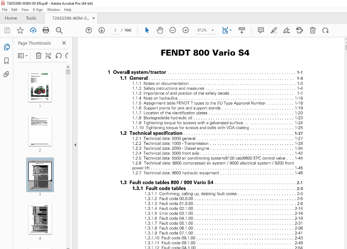
1 Overall system/tractor 1-1
11 General 1-3
1 11 Notes on documentation 1-3
1 12 Safety instructions and measures 1-4
113 Importance of and position of the safety decals 1-7
114 Note on hydraulics 1-18
115 Assignment table FENDT T types to the EU Type Approval Number 1-18
116 Support points for jack and support stands 1-19
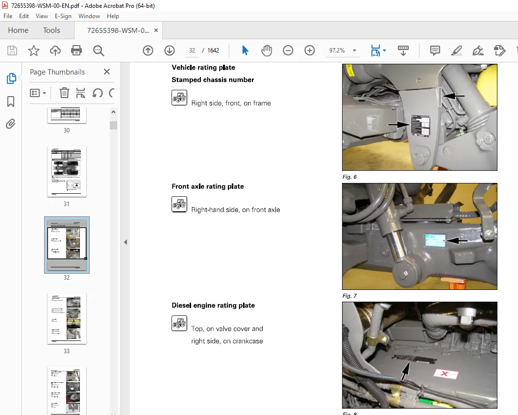
1 1 7 Location of the identification plates 1-20
1 18 Biodegradable hydraulic oil 1-23
119 Tightening torque for screws with a galvanized surface 1-24
1 110 Tightening torque for screws and bolts with VDA coating 1-25
12 Technical specification 1-27
121 Technical data: 0000 general 1-27
122 Technical data: 1000- Transmission 1-28
123 Technical data: 2000 – Diesel engine 1-34
124 Technical data: 3000 front axle 1-42
125 Technical data: 5500 air conditioning system/8100 cab/8600 EPC control valve 1-44
126 Technical data: 8800 compressed air system/ 9000 electrical system/ 9200 front
power lift 1-45
127 Technical data: 9600 hydraulic equipment 1-46
13 Fault code tables 800 / 900 Vario S4 2-1
131 Fault code tables 2-3
1311 Confirming, calling up, deleting fault codes 2-3
1312 Fault code 00000 2-5
1313 Fault code 01 000 2-8
1314 Fault code 02100 2-14
1315 Error code 03100 2-16
1316 Fault code 04100 2-18
1317 Fault code 05100 2-31
1318 Fault code 06100 2-36
1319 Fault code 07 100 2-41
13110 Fault code 08100 2-43
13111 Fault code 09100 2-49
13112 Fault code 0A1 00 2-54
13113 Fault code 0B100 2-73
13114 Faultcode0D100 2-76
13115 Fault code 0E100 2-79
13116 Error code 0F100 2-84
13117 Fault code 10100 2-88
13118 Fault code 12100 2-89
13119 Fault code 15100 2-97
13120 Fault code 17 100 2-98
13121 Fault code 1801 00 2-99
13122 Fault code 1 D100 2-102
13123 Fault code 1F100 2-115
13124 Fault code 20100 2-116
13125 Calibration fault codes 2-121
14 Component position 1-131
141 Electrical/electronic components – A 1-131
FENDT 800 Vario S4
X990 005530 013
Table of contents
142 Electrical/electronic components – B 1-137
143 Electrical/electronic components – E 1-149
144 Electrical/electronic components – F 1-160
145 Electrical/electronic components – G 1-160
146 Electrical/electronic components – H 1-161
14 7 Electrical/electronic components – K 1-162
148 Electrical/electronic components – M 1-165
149 Electrical/electronic components – R 1-168
1410 Electrical/electronic components – S 1-170
1411 Electrical/electronic components – U 1-177
1412 Electrical/electronic components – X (001-1000) 1-178
1413 Electrical/electronic components – X (1001-2000) 1-184
1414 Electrical/electronic components – X (2001-4000) 1-190
1415 Electrical/electronic components – X (4001-6000) 1-193
1416 Electrical/electronic components – Y 1-225
1417 Hydraulic components 1-233
15 Calibrations 1-266
151 Adjustments – General 1-266
1511 Calibration notes 1-266
152 Adjustments – Gearbox 1-266
1521 Calibration 4001 clutch pedal 1-266
1522 Calibration 4002: Hand throttle 1-269
1523 Calibration 4003: Travel range selector 1-272
1524 Calibration 4005 driving pedal 1-276
1525 Calibration 4007: Transmission ratio characteristic 1-278
1526 Calibration 4009: Turbo-clutch function 1-282
1527 Calibration 4010 driving pedal resolution 1-286
153 Adjustments – Sensors and functions 1-289
1531 Calibration 1001 crossgate lever 1-289
1532 Calibration 1003/1004/1005/1006 Linear modules 1-295
1533 Calibration 2401 steering angle sensor 1-299
1534 Calibration 2401 – checking the calibration accuracy 1-303
1535 Calibration 2403: Steering valve, when required 1-305
1536 Calibration 6034: Rear PTO clutch 1-309
1537 Calibration 7034 front PTO clutch 1-312
1538 Calibration 7666: Front axle suspension 1-315
1539 Calibration 8001 rear EPC – depth control 1-318
15310 Calibration 8002: Rear EPC – position control 1-321
15311 Calibration 9001 front EPC – depth control 1-325
15312 Calibration 9002 front EPC – position control 1-328
15313 Heating valve calibration – automatic air-conditioning system 1-331
15314 Speed display calibration 1-333
3 Gearbox 3-1
31 Gearbox control 3-3
311 Transmission control system functional sequence 3-3
312 Gearbox hydraulics wiring diagram – 842 100000002 3-7
31 3 Transmission function diagram 3-10
31 4 Position of transmission components 3-16
315 Hydraulic pressure measuring points on transmission and comfort controls 3-23
31 6 Measuring transmission pressure 3-26
317 Transmission pressure measurement (fax template) 3-26
318 Transmission comfort control functions pressure measurement report: Fax
template 3-28
319 Test the clutch/turbo-clutch valve 3-29
32 Differential unit 3-32
321 Dismantling differential 3-32
FENDT 800 Vario S4
X990 005530013
Table of contents
322 Assemble the differential 3-37
323 Dismantling the pinion shaft 3-43
324 Adjusting and fitting the pinion shaft 3-47
325 Install differential and set backlash 3-55
33 Final drive axle 3-61
331 Remove final drive axle 3-61
332 Install final drive axle 3-65
333 Dismantling and reassembling final drive axle 3-69
334 Technical drawing of drive axle with TPMS 3-84
34 Brake system 3-86
341 Warning 3-86
342 Hydraulic brake system: single-circuit brake, 1 pedal 3-87
343 Hydraulic brake system: single-circuit brake, 2 pedals 3-90
344 Hydraulic brake system: dual-circuit, 1 pedal 3-93
345 Connection assignment on the brake valve block for the trailer spool valve 3-96
346 Hand brake emergency release 3-99
347 Check hydraulic brake system 3-100
348 Technical drawing of rear wheel brake 3-103
349 Component location – Brake 3-104
3410 Dismantle rear wheel brake 3-108
3411 Install rear wheel brake 3-110
3412 Bleed the hydraulic brake system 3-114
3413 Adjust the S105/106 brake switch 3-116
3414 Check the pilot control for the pneumatic trailer brake 3-118
35 Vario insert 3-119
351 Remove the Vario insert 3-119
352 Fit the Vario insert 3-129
353 Top up the transmission oil 3-139
354 Remove actuator shaft 3-140
355 Fit actuator shaft 3-142
356 Remove connecting rod 3-146
357 Fit coupling rod 3-148
358 Dismantle control housing 3-151
359 Fit control housing 3-153
3510 Install B014 hydrostatic collecting shaft sensor 3-155
3511 Install B015 bevel pinion sensor 3-158
36 Cardan brake 3-161
361 Technical drawing of Cardan shaft brake 3-161
362 Remove cardan shaft brake 3-163
363 Installing cardan shaft brake 3-167
3 7 Front PTO 3-178
3 7 1 Front PTO valve block 3-178
3 7 2 Front PTO transmission 3-179
373 Front PTO drive 3-180
374 Remove front PTO clutch 3-182
375 FitthefrontPTOclutch 3-190
376 Remove front PTO pump 3-197
377 Install front PTO pump 3-199
378 Remove front PTO stub shaft 3-201
379 Install front PTO stub shaft 3-203
38 Rear PTO 3-204
381 Technical drawing of rear PTO 3-204
382 Remove of rear PTO clutch 3-207
383 Install rear PTO clutch 3-215
384 Remove and dismantle rear PTO transmission 3-224
385 Install rear PTO transmission 3-229
39 Front wheel drive 3-235
FENDT 800 Vario S4
X990 005530 013
Table of contents
391 Technical drawing: Front-wheel drive shaft 3-235
392 Removing and dismantling the front wheel drive clutch 3-237
393 Fit the front wheel drive clutch 3-241
310 Hydrodamp 3-249
3101 Remove the hydrodamp 3-249
3102 Fit the hydrodamp 3-251
4 Engine 4-1
41 Engine 4-3
411 Faults on the Common Rail diesel engine (without fault code) 4-3
412 Special tools for diesel engines (Deutz) 4-7
413 Fax template for determining the specific engine lubricating oil consumption 4-33
414 Determining engine power – comparison of standards and directives 4-37
415 Calculating the fuel consumption of a diesel engine 4-38
416 PTO power measurement 4-46
417 General description of the common rail system 4-48
418 Emergency operation (emergency function) 4-51
419 Deutz TCD/TTCD diesel engines: Automatic system calibration 4-52
4110 A099 – engine control unit 4-71
4111 8055 – foot throttle sensor 4-75
4112 8085 camshaft speed sensor 4-76
4113 8086 rail pressure sensor 4-78
4114 8087 fuel low pressure sensor 4-80
4115 8088 – sensor, crankshaft speed 4-81
4116 8089 engine temperature sensor (Deutz) 4-82
4117 8090 oil pressure sensor 4-83
4118 8091 – water in fuel sensor 4-83
4119 8092 charge air pressure/temperature sensor 4-85
4120 Starter control 4-86
42 Cylinder head 4-88
421 Adjust the valves 4-88
422 Remove and install the injector and injector sleeve 4-98
43 Cooling system 4-125
431 Coolant circuit TTCD 61 4-125
44 Fuel system 4-127
441 Fuel system 4-127
442 Pressure checking (Deutz TCD 41/61/78) common rail system “High-pressure
system 1600/2000 bar operating pressure”, test injector, Y091 dispensing unit, test highpressure
pump 4-128
443 Water sedimentor (pre-filter) 4-192
444 Fuel pump A–193
445 Y091 – dispensing unit (fuel) 4-193
446 High-pressure pump (PF 45) 4-197
447 High-pressure accumulator: Common rail 4-198
448 Design and function of the high-pressure relief valve 4-199
449 Y095 to Y101 – Injectors 1 to 6 4-200
4410 Measuring fuel return pressure A–204
4411 Measuring low fuel pressure 4-211
4412 Measuring low fuel pressure at the Y091 dispensing unit 4-215
4413 Removing and installing the high-pressure limiting valve and rail pressure sensor 4-217
4414 Bleeding air from the fuel system 4-220
45 Exhaust gas system 4-222
451 Charge air system and exhaust gas after-treatment 4-222
452 CSF particulate filter for reducing soot particles 4-228
453 SCR catalytic converter 4-233
454 Components of the exhaust after-treatment system 4-238
FENDT 800 Vario S4
X990 005530013
Table of contents
455 Fault analysis on A084 supply module / Y120 “Ad8Iue” (read faults / flush / check
SCR system) 4-243
456 Ad8Iue dosing system diagnostics using the FENDIAS diagnostics program
(Deutz-Serdia) 4-281
457 Ad8Iue dosing system: Ad8Iue consumption and fuel consumption 4-300
5 Overall system/front axle 5-1
51 Suspension 5-3
511 Functional plans 5-3
512 Disassemble and reassemble suspension cylinder 5-10
52 Cardan shaft 5-12
521 Technical drawing: Front-wheel drive shaft 5-12
6 Steering 6-1
61 Steering 6-3
611 Steering hydraulics 6-3
612 Steering hydraulics 6-4
613 Steering monitoring 6-8
614 Remove the steering servo unit 6-10
615 Install the steering servo unit 6-13
616 Remove the RUFA steering servo unit 6-16
7 Vehicle layout 7-1
71 Layout 7-3
7 11 Remove, install and repair turntable from operator’s seat (Rufa) 7-3
8 Overall system/air conditioning system 8-1
81 Air-conditioning system 8-3
811 Diagram: Automatic air conditioning system 8-3
812 Air conditioning unit service hatch 8-6
813 Removing the air conditioning unit (HVAC) 8-8
814 Installing the air conditioning unit (HVAC) 8-13
815 Removing the air box (8071, M015, M016) 8-18
816 Installing the air box 8-20
817 Assembly and disassembly of the dryer module for the air conditioning condenser
8-23
9 Cab 9-1
91 Cab 9-3
911 Reverse drive control function and operation 9-3
912 Remove the cab 9-7
913 Attaching the cab 9-15
914 Glue in the front windscreen 9-22
915 Tightening torques of the door furniture 9-28
10 Power lift/EPC electro-hydraulic control 10-1
101 Power lift/EPC electro-hydraulic control 10-3
1011 Slip control system operation and function 10-3
1012 Functional description of 8031/8032 – draft sensing pin left/right 10-4
1013 EPC valves 10-8
1014 Functional plans 10-13
1015 Lower link stabilizer functional plan 10-25
1016 Remove the rear EPC valve 10-26
1017 Fit the rear EPC valve 10-29
1018 Dismantle the rear pressure relief valve DW Y062 10-34
1019 Assemble the rear pressure relief valve DW Y062 10-35
FENDT 800 Vario S4
X990 005530 013
Table of contents
102 Power lift control 10-36
1021 Technical drawing of the hydr lower linkage support 10-36
1022 Remove the lower linkage stabilizer solenoid valve Y082/Y083 10-40
1023 Install the Y082/Y083 lower link stabilizer solenoid valves 10-41
11 Overall system/compressed air system 11-1
111 Compressed air system 11-3
11 11 Compressed air system (area: trailer brake) 11-3
11 12 Compressed air system diagram – 842880000001 _b 11-10
11 13 Compressed air system diagram – 842880000002 11-13
11 14 Tightening torques for compressed-air connection system 11-15
11 15 “VarioGrip” tire pressure monitoring system, function and layout 11-17
12 Electrical system 12-1
121 Electrical system 12-5
1211 Circuit diagrams for A050 – basic control ECU 12-5
122 Measure and test – A components 12-12
1221 A007 – instrument panel 12-12
1222 A009 – actuator unit 12-24
1223 Installing A009 actuator unit 12-32
1224 A011 – radar sensor 12-38
1225 A013 – circuit board, microfuses 12-41
1226 A036 – “dashboard” control panel 12-47
1227 A038 – relay; +supply; K BUS 12-51
1228 A038 – head light, side light, direction indicator 12-62
1229 A038 – horn, rotating beacon, wide vehicle marker 12-68
12210 A038 – work lights 12-70
12211 A038- interior lighting 12-73
12212 A038 – mirror heating, rear window heating, windscreen heating; windscreen
wipers 12-75
12213 A038 – automatic air conditioning system (heating, air conditioning, ventilation) 12-79
12214 A038-sockets 12-85
12215 A038 – Starter and tank pump 12-94
12216 A038 – reverse drive control (Ruta) 12-97
12217 A038 Work light activation 12-103
12218 Test A038 with 160-pin adapter box 12-111
12219 A050 – basic control unit ECU 12-114
12220 A050 – CAN BUS (K BUS, G BUS, V BUS, ISO BUS) 12-118
12221 Test A050 with 160-pin adapter box 12-126
12222 A077 – immobilizer ECU: Functional description 12-128
12223 A077 – immobilizer ECU 12-129
12224 A082 – nitrogen oxide NOx sensor 1, upstream of SCR (Not G3) 12-131
12225 A083 – nitrogen oxide NOx sensor 2, downstream of SCR (Not G3) 12-132
12226 A084 – Ad Blue module (Not G3) 12-133
12227 A087 – tire pressure monitoring system (TPMS) 12-135
12228 A099 – ECU engine control unit (EDC 17) 12-137
12229 Test A099 with 160-pin adapter box 12-143
12230 A100-MFA, multifunction armrest 12-145
12231 Test A 100 with 160-pin adapter box 12-152
12232 A 133 – air intake throttle ECU 12-154
12233 A 134 – exhaust gas recirculation ECU 12-155
12234 A 136 – wastegate ECU 12-157
12235 A 177 – AGCO Connectivity Module (ACM) 12-158
123 Measure and test – B components 12-160
1231 B002 – front PTO speed sensor 12-160
1232 B003 – front axle suspension position sensor 12-161
1233 B004 – vacuum switch (air filter) 12-162
FENDT 800 Vario S4
X990 005530013
Table of contents
1234 B007 – fuel level sensor 12-164
1235 B008 – High pressure sensor 1 12-166
1236 B009 – discharge temperature sensor 12-168
1237 B013 – hydraulic oil temperature sensor 12-169
1238 B014 – Collecting shaft speed sensor 12-171
1239 B015 – bevel pinion sensor 12-172
12310 B016 – travel speed range detection sensor 12-174
12311 B017 – clutch pedal sensor 12-175
12312 B020 – rear PTO (stub shaft) speed sensor 12-176
12313 B021 – rear PTO clutch speed sensor 12-177
12314 B031 – right draft sensing pin 12-179
12315 B032 left-hand draft sensing pin sensor 12-180
12316 B039 – high pressure sensor 2 12-182
12317 B040 – Front power lift position sensor 12-184
12318 B055 – foot throttle sensor 12-185
12319 B060 compressed air supply sensor 12-186
12320 B071 – output temperature sensor 12-188
12321 B073 – Solar thermal radiation sensor 12-189
12322 B07 4 – interior temperature sensor 12-191
12323 B076 – exterior temperature sensor 12-193
12324 B081 – steering wheel sensor (360°) 12-195
12325 B084 – hydraulic oil level sensor 12-197
12326 B085 – camshaft speed sensor 12-199
12327 B086 – rail pressure sensor 12-202
12328 B087 – low fuel pressure sensor 12-205
12329 B088 – sensor, crankshaft speed 12-207
12330 B089 – engine temperature sensor (Deutz) 12-210
12331 B090 – oil pressure sensor 12-213
12332 B091 – water in fuel sensor 12-215
12333 B092 – boost pressure/charge air temperature sensor 12-216
12334 B097 – brake pressure sensor 12-219
12335 B 102 – Ad Blue temperature and level sensor 12-222
12336 B 105 – Exhaust gas temperature sensor upstream of SCR (Not G3) 12-225
12337 B 145 – rear power lift position sensor 12-227
12338 B 168 – steering angle sensor 12-228
12339 B 187 – evaporator temperature sensor 12-229
12340 B 191 – Exhaust gas pressure sensor upstream of turbo 12-231
12341 B 192 – CSF differential pressure sensor (Not G3) 12-232
12342 B 193 – exhaust temperature upstream of CSF sensor (Not G3) 12-234
12343 B 194 – pressure downstream of CSF sensor (Not G3) 12-236
12344 B217 – temperature sensor downstream of venturi (Not G3) 12-237
12345 B218 – venturi differential pressure sensor (Not G3) 12-239
12346 B283 – Supply pressure monitoring sensor 2 12-240
12347 B284 – Supply pressure monitoring sensor 1 12-242
12348 B290 – Brake pedal lock sensor 12-244
124 Measure and test – CAN bus 12-246
1241 Measure the CAN bus 12-246
125 Measure and test – E components 12-249
1251 E050 to E280 – work lights 12-249
1252 E063 – air-dryer heater element (temperature-controlled) 12-249
1253 E216 – AdBlue heater suction and return line and E217 – AdBlue heater pressure
line 12-251
126 Measure and test – G components 12-253
1261 G001 – battery 12-253
1262 G002/G004 – right/left alternators 12-254
127 Measure and test – H components 12-257
1271 H011 – horn 12-257
FENDT 800 Vario S4
X990 005530 013
Table of contents
128 Measure and test – K components 12-258
1281 K063 – Grid heater flange relay 12-258
1282 K065 – starter relay 12-259
1283 K083 – Ad Blue relay 12-259
1284 K090 – Ad Blue module heater relay 12-260
1285 K091 – Ad Blue heating relay for suction and return line 12-261
1286 K092 – Ad Blue heating relay for pressure line 12-261
129 Measure and test – M components 12-262
1291 M001 – starter 12-262
1292 M003/M005 – front/rear screen washer pumps 12-266
1293 M004 – rear wiper motor 12-267
1294 M015/M016 – actuator motor for ventilation air flap 12-269
1295 M017 – primary fan 12-271
1296 M046/M047 – headlight actuator motor (headlight adjustment) 12-273
1297 M048 – main fan 12-275
1298 M049 – heater valve 12-277
1299 M054 – cooling water pump 12-278
12910 M055 – front wiper motor 12-279
1210 Measure and test – S components 12-281
12101 S017 – filter contamination switch 12-281
12102 S019 – left external rear PTO button 12-282
12103 S020 – right external rear PTO button 12-283
12104 S021/S022 – external front power lift button 12-285
12105 S025 – variable displacement pump pressure monitoring switch 12-286
12106 S027/S028/S029/S030 – external (rear power lift) buttons 12-287
12107 S034 – coolant level switch 12-289
12108 S035 High & low-pressure switch for air conditioning system 12-290
12109 S045 reverse drive switch 12-291
121010 S047 – engine brake switch 12-293
121011 S053 – driver seat switch 12-293
121012 S067 /S068 – external valve button 12-295
121013 S074 – starter lockout switch 12-296
121014 S075 – Wheel driven steering pump flow monitor switch 12-298
121015 SOSO – hand brake switch 12-299
121016 S085 – reverse drive (RUFA) actuation switch 12-300
121017 S105/S106 – left/right brake switches 12-301
121018 S119 – hydraulic oil filter contamination switch 12-302
121019 S134 – auxiliary pump pressure monitor switch 12-303
121020 S157 – forward/reverse shuttle switch 12-304
121021 S174/175 – right-hand external valve actuation button 12-305
1211 Measure and test- X components 12-308
1211 1 X007 – “black” implement socket 12-308
1211 2 X008 – counter input (onboard computer) “blue” 12-310
1211 3 X015 – external control, rear EPC (external position sensor) 12-313
1211 4 X015 external control (Area: 3rd and 4th hydraulic circuit) 12-315
1211 5 X015 – external control socket (area: automatic steering axle mode) 12-316
1211 6 X017 – front socket (with front power lift only) 12-322
1211 7 X018 – trailer socket 12-323
1211 8 X028 – cab ISO socket 12-324
1211 9 X400 ISO BUS PCB (implement socket) 12-325
1211 10 X1048 ABS socket (anti-lock system on trailer) 12-335
1212 Measure and test- Y components 12-337
12121 Y002 – travel speed range I solenoid valve 12-337
12122 Y003 – travel speed range 11 solenoid valve 12-338
12123 Y004 clutch/turbo-clutch solenoid valve 12-340
12124 Y005 – Speed limiter solenoid valve 12-341
12125 Y008 – rear PTO (clutch) solenoid valve 12-343
FENDT 800 Vario S4
X990 005530013
Table of contents
12126 Y009 – 4WD solenoid valve 12-344
12127 Y010 – differential lock solenoid valve 12-346
12128 Y011 – front PTO (clutch) solenoid valve 12-347
12129 Y012 – suspension loading/oil preheating solenoid valve 12-349
121210 Y013 – Suspension lowering solenoid valve 12-350
121211 Y021 – raise solenoid valve (standard front power lift) 12-352
121212 Y021 – front pressure compensator lock valve 12-353
121213 Y022 – standard front power lift lowering solenoid valve 12-355
121214 Y026/Y027 – rear PTO stage 1/1 I selection solenoid valve 12-356
121215 Y032 – control pressure solenoid valve 12-358
121216 Y055 – rear pressure compensator lock valve 12-359
121217 Y060 – hydraulic oil preheater solenoid valve 12-361
121218 Y062 – rear field pressure control solenoid valve 12-362
121219 Y063 – wobble stabilizer solenoid valve 12-364
121220 Y065 – Suspension raising solenoid valve 12-365
121221 Y067 – Suspension locking solenoid valve 12-367
121222 Y082/Y083 – lock and release lower link stabilizer solenoid valve 12-368
121223 Y084 – power beyond solenoid valve 12-370
121224 Y091 – fuel dispensing unit 12-371
121225 Y092/Y093 – reverse drive (ROFA) rotation solenoid valves 12-372
121226 Y095 to Y098, Y100, Y101 – injectors 1 to 6 12-374
121227 Y120 – Ad Blue metering valve 12-378
121228 Y168 – front ground pressure control solenoid valve 12-380
121229 Y169 – Ad Blue tank heater solenoid valve 12-382
121230 Y170 – engine brake solenoid valve 12-384
121231 Y176-Y185 12-385
121232 Y209 – reversible fan (Hagele) 12-387
121233 Y222 – Visco fan (Viscotronic) 12-391
121234 Y241 – Air dryer solenoid valve 12-393
13 Hydraulic pump installation 13-1
131 Hydraulic pump installation 13-3
1311 Fit wheel-driven emergency steering pump 13-3
14 Hydraulic pipes 14-1
141 Hydraulic trailer brake 14-3
1411 Function of the hydraulic trailer brake (French and Italian versions) 14-3
142 Reverse operation 14-27
1421 Technical drawing of the turntable (reverse drive) 14-27
1422 Seal the turntable 14-33
15 Overall system/hydraulic equipment 15-1
151 Hydraulic equipment 15-3
1511 Pressure control – PR (LS pump) 15-3
1512 Pressure measuring points overview 15-6
1513 External pressure rise (Power Beyond) 15-7
1514 Test report, fax template 15-8
1515 SB 33 EHS 1 RD spool valves 15-11
1516 Central control block 15-12
16 Electronics 16-1
161 Electronics 16-3
1611 Fendt 800 Vario Tier I I lb electronics concept 16-3
1612 Functional description of the A050 basic control ECU 16-9
17 Service 17-1
171 Special tools 17-3
FENDT 800 Vario S4
X990 005530 013
Table of contents
1711 Special tools 17-3
172 FENDIAS 17-4
1721 EOL programming 17-4
1722 Programming the immobilizer – introduction 17-10
1723 Teaching in the vehicle key 17-12
1724 Create activation package 17-16
1725 Apply activation package 17-19
1726 Replace components 17-22
11 General 1-3
11 1 Notes on documentation 1-3
11 2 Safety instructions and measures 1-4
113 Importance of and position of the safety decals 1-7
11 4 Note on hydraulics 1-18
115 Assignment table FENDT T types to the EU Type Approval Number 1-18
116 Support points for jack and support stands 1-19
11 7 Location of the identification plates 1-20
11 8 Biodegradable hydraulic oil 1-23
119 Tightening torque for screws with a galvanized surface 1-24
1110 Tightening torque for screws and bolts with VDA coating 1-25
12 Technical specification 1-27
121 Technical data: 0000 general 1-27
122 Technical data: 1000 – Transmission 1-28
123 Technical data: 2000 – Diesel engine 1-34
124 Technical data: 3000 front axle 1-42
125 Technical data: 5500 air conditioning system/8100 cab/8600 EPC control valve 1-44
126 Technical data: 8800 compressed air system/ 9000 electrical system/ 9200 front power
lift 1-45
127 Technical data: 9600 hydraulic equipment 1-46
13 Fault code tables 800 / 900 Vario S4 2-1
131 Fault code tables 2-3
1311 Confirming, calling up, deleting fault codes 2-3
1312 Fault code 00000 2-5
1313 Fault code 01 000 2-8
1 314 Fault code 02100 2-14
1315 Error code 03100 2-16
1316 Fault code 04100 2-18
1317 Fault code 05100 2-31
1318 Fault code 06100 2-36
1319 Fault code 07100 2-41
13110 Fault code 08100 2-43
13111 Fault code 09100 2-49
13112 Fault code 0A1 00 2-54
13113 Fault code 0B100 2-73
13114 Fault code 0D100 2-76
13115 Fault code 0E100 2-79
13116 Error code 0F100 2-84
13117 Fault code 10100 2-88
13118 Fault code 12100 2-89
13119 Fault code 15100 2-97
13120 Fault code 17100 2-98
13121 Fault code 1801 00 2-99
13122 Fault code 1 D100 2-102
13123 Fault code 1F100 2-115
13124 Fault code 20100 2-116
13125 Calibration fault codes 2-121
14 Component position 1-131
141 Electrical/electronic components – A 1-131
FENDT 800 Vario S4
X990 005530 013
1-1
Table of contents
1 42 Electrical/electronic components – B 1-137
1 43 Electrical/electronic components – E 1-149
1 44 Electrical/electronic components – F 1-160
1 45 Electrical/electronic components – G 1-160
1 46 Electrical/electronic components – H 1-161
1 4 7 Electrical/electronic components – K 1-162
1 48 Electrical/electronic components – M 1-165
1 49 Electrical/electronic components – R 1-168
1410 Electrical/electronic components – S 1-170
1411 Electrical/electronic components – U 1-177
1412 Electrical/electronic components – X (001-1000) 1-178
1413 Electrical/electronic components – X (1001-2000) 1-184
1414 Electrical/electronic components – X (2001-4000) 1-190
1415 Electrical/electronic components – X (4001-6000) 1-193
1416 Electrical/electronic components – Y 1-225
1 417 Hydraulic components 1-233
15 Calibrations 1-266
1-2
151 Adjustments – General 1-266
1511 Calibration notes 1-266
152 Adjustments – Gearbox 1-266
1521 Calibration 4001 clutch pedal 1-266
1522 Calibration 4002: Hand throttle 1-269
1523 Calibration 4003: Travel range selector 1-272
1524 Calibration 4005 driving pedal 1-276
1525 Calibration 4007: Transmission ratio characteristic 1-278
1526 Calibration 4009: Turbo-clutch function 1-282
1527 Calibration 4010 driving pedal resolution 1-286
153 Adjustments – Sensors and functions 1-289
1531 Calibration 1001 crossgate lever 1-289
1532 Calibration 1003/1004/1005/1006 Linear modules 1-295
1533 Calibration 2401 steering angle sensor 1-299
1534 Calibration 2401 – checking the calibration accuracy 1-303
1535 Calibration 2403: Steering valve, when required 1-305
1536 Calibration 6034: Rear PTO clutch 1-309
1537 Calibration 7034 front PTO clutch 1-312
1538 Calibration 7666: Front axle suspension 1-315
1539 Calibration 8001 rear EPC – depth control 1-318
15310 Calibration 8002: Rear EPC – position control 1-321
15311 Calibration 9001 front EPC – depth control 1-325
15312 Calibration 9002 front EPC – position control 1-328
15313 Heating valve calibration – automatic air-conditioning system 1-331
15314 Speed display calibration 1-333
FENDT
IMAGES PREVIEW OF THE MANUAL:
Need help? Contact: [email protected]
S.M 7/24