

Fassi crane installation instructions Manual
FILE DETAILS:
Fassi crane installation instructions Manual
Language : English
Pages : 242
Downloadable : YES
Format : PDF
Size : 38.9 MB
DESCRIPTION:
Fassi crane installation instructions Manual
GENERAL:
1.1. GENERAL INDICATIONS:
The aim of this handbook is to provide instructions, diagrams, directions and basic guidelines for correct crane and vehicle assembly and for the execution of a series of tests after assembly in order to check operation. Before starting to mount the crane on the vehicle, read this handbook carefully and also the vehicle manufacturer’s handbook. Make sure you always follow the instructions to the letter. In case of doubt, contact the “AFTER SALE SERVICE” office of the crane manufacturer. The crane must be mounted on the vehicle only at centres licensed by the Manufacturer. These centres must be operated by skilled personnel and comply with these specifications. FASSI reserves the right to change the installation instructions at any moment or to provide specific installation instructions related to a crane model that could deviate from these general installation instructions. When making changes or fitting any type of equipment it is a general rule not to alter anything affecting proper operation of assemblies and vehicle members when running.
For example:
· There must be free access to all points requiring inspection, maintenance or periodical checks. In the case of enclosed superstructures, special openings and accesses must be provided.
· Liberty of movement must be ensured for tip-up cabs; in case of superstructures over the cab, it is important to ensure a suitable air flow.
· It must be possible to dismantle the various assemblies for servicing. For example: service to the gearbox or clutch must be done without the need to dismantle the main parts of the structure to be fitted.
· The cooling system (calander, radiator, air ducts, cooling circuits, etc.) and the engine air intake system must not be altered.
· Sound-proof panels must not be altered or removed so as not to change the vehicle’s approved noise levels. If it is necessary to make an opening (e.g. for the longitudinal chassis sections), it must be sealed properly
using materials with the same inflammable and sound-proof characteristics of the original ones.
· The brakes and the battery cases must be properly ventilated.
· When positioning mudguards and wheelhouses, the rear wheels must have enough space to move freely even when chains are fitted.
· Upon completion of the assembly work, headlight adjustment must be checked for safety reasons and rectified if necessary. To do this, turn the headlight adjusting screw and check the trim corrector adjustment
range with a full load. Proceed as specified in the vehicle handbook, remembering to record, in it, any new values.
TABLE OF CONTENTS:
Fassi crane installation instructions Manual
1. GENERAL 5
1.1 GENERAL INDICATIONS 5
1.2 APPLICABILITY 6
1.3 MACHINERY DIRECTIVE 6
1.4 REFERENCE DIRECTIVE 7
1.5 SAFETY REQUIREMENTS 8
1.6 DEFINITION OF RESPONSIBILITIES 8
1.7 PRECAUTIONS ABOUT THE RISKS DURING THE INSTALLATION OPERATIONS 9
1.8 REFERENCES FOR THE INSTALLER 1 0
1.9 CRANE MODEL IDENTIFICATION CODES 20
1.10 DEFINITION OF MAIN CRANE AND INSTALLATION COMPONENTS 2 2
1.11 DEFINITION OF MAIN CRANE ACCESSORIES 23
1.12 DEFINITION OF THE MAIN COMPONENTS OF THE INSTALLATION 2 4
1.13 IDENTIFICATION OF THE CRANE AND ACCESSORIES SERIAL NUMBER _ _____________ _ 24
2. CRANE-VEHICLE COMBINATIONS 27
2.1 COMBINATION PRINCIPLES 2 7
2.2 DETERMINATION OF AXLE LOADS 2 7
2.2.1 Where to find the technical data 2 8
2.2.2 2-axle vehicle / crane mounted behind cab 3 1
2.2.3 3-axle vehicle / crane mounted behind cab 3 4
2.2.4 2-axle vehicle / rear mounted crane 3 9
2.2.5 3-axle vehicle / rear mounted crane 4 2
2.2.6 Tractor truck / crane mounted behind cab 4 7
2.2.7 Example of axle loads distribution using Fassi FIP program 5 0
2.3 THEORETICAL STABILITY ANALYSIS – ANALYTICAL METHOD 5 1
2.3.1 Crane behind cab 5 1
2.3.2 Crane mounted on the rear 5 9
2.3.3 Crane mounted on three axle vehicles 6 7
2.3.4 Theoretical stability check using a graph 6 8
2.4 Example of theoretical stability check using the Fassi “FIP” program 6 9
3. SIZING 7 0
3.1 CHECKING THE VEHICLE CHASSIS AND CRANE SUB FRAME 7 0
3.1.1 Sub frame material 7 7
3.1.2 Sub frame end tapering 77
3.1.3 Length of sub frame 7 9
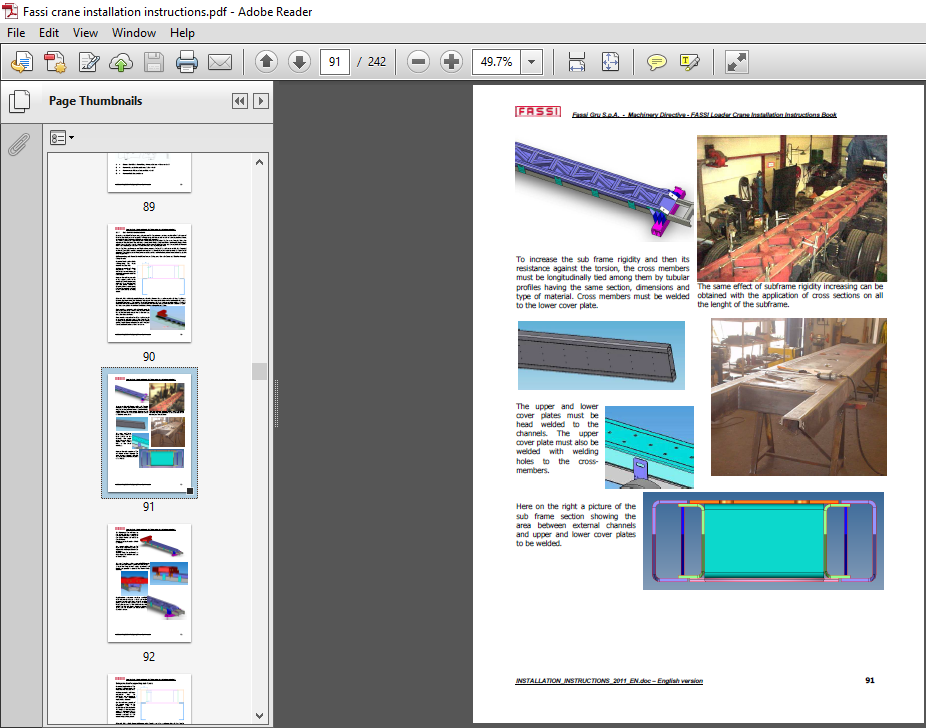
3.1.4 Connecting cross members 8 1
3.1.5 Sub frame construction 8 4
3.1.6 Securing the sub frame 8 6
3.1.7 Self supporting sub frame 9 0
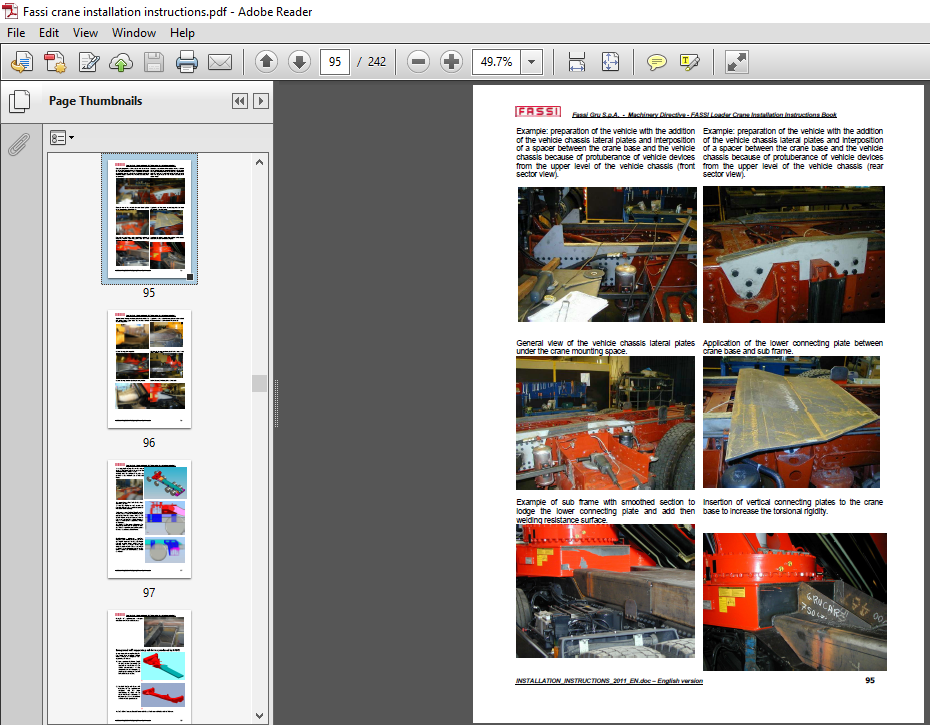
3.2 CRANE ANCHORING 9 9
3.2.1 Tie rods 1 0 2
3.2.2 Blocks and plates 1 0 4
3.2.3 Tie rod nuts and counter nuts 1 0 4
3.2.4 Devices preventing the vehicle chassis from getting crushed 1 0 4
3.2.5 Identification and modification of the rotation dead point 1 0 5
4. SUPPLEMENTARY OUTRIGGERS MOUNTING 1 0 7
4.1 GENERAL 1 0 7
4.2 FREE SPACE UNDER THE OUTRIGGER RAM 1 0 7
4.3 SUPPLEMENTARY OUTRIGGERS INSTALLATION 1 0 8
4.3.1 Above-chassis mounting 1 0 8
4.3.2 Under-chassis mounting 1 09
Fassi Gru S.p.A. – Machinery Directive – FASSI Loader Crane Installation Instructions Book
INSTALLATION_INSTRUCTIONS_2011_EN.doc – English version 3
4.4 HYDRAULIC CONNECTIONS FOR THE SUPPLEMENTARY OUTRIGGERS 109
4.5 CALCULATION OF BOLTS Q.TY TO FIX SUPPLEMENTARY OUTRIGGERS 1 0 9
4.6 SPECIAL SUPPLEMENTARY OUTRIGGERS INSTALLATIONS 1 1 0
4.6.1 Under cabin mounting 1 1 0
4.6.2 Extra supplementary outriggers mounted on the rear of the vehicle 112
5. POWER TAKE-OFF AND PUMP 1 17
5.1 GENERAL 1 17
5.2 SELECTING THE POWER TAKE-OFF AND PUMP 1 17
5.3 INSTALLING POWER TAKE-OFF ON GEAR BOX 1 21
5.3.1 Limitations 1 21
5.3.2 Final check 121
5.4 POWER TAKE OFF – SPECIAL CASES 122
5.5 PNEUMATIC COUPLING OF POWER TAKE-OFF 123
5.6 MECHANICAL COUPLING OF POWER TAKE-OFF 123
5.7 INSTALLING THE PUMP 124
5.7.1 How to start up piston pumps 126
5.7.2 Adjustment of the engine speed 1 2 6
5.8 CRANE OPERATED THROUGH AN ALTERNATIVE POWER GROUP 126
6. HYDRAULIC SYSTEM 1 28
6.1 DIMENSION OF THE SUCTION LINE 1 2 8
6.2 DIMENSION OF THE PRESSURE LINE 1 2 9
6.3 PIPES FOR THE HYDRAULIC CONNECTION OF THE SUPPLEMENTARY OUTRIGGERS 1 3 1
6.4 FILLING-UP OF THE OIL TANK 1 3 1
7. ELECTRIC SYSTEM 132
7.1 SUPPLY LINE CONNECTION TO THE VEHICLE 1 3 3
7.1.1 Supply line for cranes with FX800 electronic system 134
7.1.2 Supply line for cranes with FX500 electronic system 1 3 5
7.1.3 Supply line for the FX804 slave unit for FX800 electronic system 1 3 5
7.1.4 Supply line for the FX504 slave unit for FX500 electronic system 1 3 6
7.1.5 Cable for radio remote control options for FX800 electronic system 1 3 6
7.1.6 Cable for radio remote control options for FX500 electronic system 1 3 7
7.1.7 Supply cable for user panels for FX800 electronic system 1 3 8
7.1.8 Supply cable for working lights for FX800 electronic system 1 3 9
7.1.9 Supply cable for working lights for FX500 electronic system 1 3 9
7.1.10 Supply cable for height sensor for FX800 electronic system 1 4 0
7.1.11 Supply cable for height sensor for FX500 electronic system 1 4 0
7.1.12 Supply cable for oil cooler for FX800 electronic system 1 4 1
7.1.13 Supply cable for oil cooler for FX500 electronic system 141
7.1.14 Signal cable from M.O.L. system 1 4 2
7.1.15 PLE signal cable for FX500 electronic system 1 4 3
7.1.16 Supply cable for DCS option for FX800 electronic system 1 4 3
7.1.17 Extra wires for eventual customer options for FX800 electronic system 1 4 4
7.1.18 Supply cable for FSC system – main unit 1 4 4
7.1.19 Supply cable for Can bus lines shunt box – IE696 1 4 5
7.1.20 Supply wire for outriggers selector to indicate the operator position 1 4 5
7.1.21 Connection cables between main FSC unit and SD2 shunt box for supplementary outriggers 1 4 6
7.1.22 Supply cable for M.O.L. system (version integrated in the FSC system) 1 4 7
8. PNEUMATIC SYSTEM 1 47
9. CRANE COMPONENTS ASSEMBLY IF NOT FITTED AT THE ORIGIN 1 4 8
9.1 APPLICATION OF THE OUTRIGGER RAMS FOR THE CRANE 1 4 8
9.1.1 Use of monocast outrigger plates 1 4 8
Fassi Gru S.p.A. – Machinery Directive – FASSI Loader Crane Installation Instructions Book
INSTALLATION_INSTRUCTIONS_2011_EN.doc – English version 4
9.2 ACCESSORIES INSTALLATION 1 4 9
9.2.1 Jib installation 1 4 9
9.2.2 Manual extensions installation 1 5 1
10. CONTROL STATION 1 5 2
10.1 ACCESS 152
10.2 PROTECTION AGAINST THE RISK OF INHALING EXHAUST FUMES 155
10.3 PROTECTION AGAINST THE RISK OF CRUSHING AND SHEARING 1 5 5
11. PRACTICAL TESTS CARRIED OUT BY THE INSTALLER 157
11.1 FUNCTIONAL TEST 157
11.2 STATIC TEST 157
11.3 DYNAMIC TEST 158
11.3.1 Sink rate of the boom system under nominal load 158
11.4 STABILITY TESTS 158
11.4.1 General 1 58
11.4.2 Test load 158
11.4.3 Test conditions 159
11.5 Stability test approval criteria 161
11.6 TEST REPORTS 163
11.7 VERIFICATION AND MEASUREMENT OF THE ACOUSTIC EMISSIONS 163
11.8 FSC SYSTEM SETTING 164
11.8.1 Setting of the FSC/L system 1 6 4
11.8.2 Setting of the FSC/M1 – FSC/M2 systems 1 6 4
11.8.3 Setting of the FSC/S system 1 6 6
12. CHECKING MAXIMUM MASS ON AXLES 174
13. RE-ADJUSTMENT AND SEALING OF THE CRANE 175
14. CRANE TRANSFORMATION 1 76
15. LIST OF HAZARDS 1 77
16. INSTRUCTION PLATES AND STICKERS 1 77
17. SPECIAL CASES AND INSTALLATION 1 77
17.1 CRANE INSTALLED ON FIX PEDESTAL 179
17.2 CRANE INSTALLED ON BOAT 1 7 9
18. TECHNICAL FILE 1 80
19. CE MARKING AND DECLARATION OF CONFORMITY 184
19.1 GENERAL 1 84
20. CRANE DELIVERY TO THE CUSTOMER/END USER 1 85
21. ENCLOSED 1 86
21.1 CHART WITH CRANE FEATURES 1 87
21.2 CHART WITH THE FEATURES OF THE SUPPLEMENTARY OUTRIGGERS 1 88
21.3 CHART WITH THE FEATURES OF THE HYDRAULIC CIRCUIT (working pressures and oil flow) 1 8 9
21.4 LIST OF HAZARDS 1 90
21.5 CE DECLARATION OF CONFORMITY ISSUED BY THE CRANE PRODUCER (fac-simile) 1 9 3
21.6 CHECK LIST (fac-simile) 1 95
21.7 LOADER CRANE LOGBOOK (fac-simile) 1 9 6
VIDEO PREVIEW OF THE MANUAL:

IMAGES PREVIEW OF THE MANUAL:

PLEASE NOTE:
- This is not a physical manual but a digital manual – meaning no physical copy will be couriered to you. The manual can be yours in the next 2 mins as once you make the payment, you will be directed to the download page IMMEDIATELY.
- This is the same manual used by the dealers inorder to diagnose your vehicle of its faults.
- Require some other service manual or have any queries: please WRITE to us at [email protected]


