Epson EPL-N4000_4000 Service Manual – PDF DOWNLOAD
$28.95
Epson EPL-N4000_4000 Service Manual – PDF DOWNLOAD
Description
Epson EPL-N4000_4000 Service Manual – PDF DOWNLOAD
FILE DETAILS:
Epson EPL-N4000_4000 Service Manual – PDF DOWNLOAD
Language :English
Pages :306
Downloadable : Yes
File Type : PDF
IMAGES PREVIEW OF THE MANUAL:
DESCRIPTION:
Epson EPL-N4000_4000 Service Manual – PDF DOWNLOAD
About This Manual
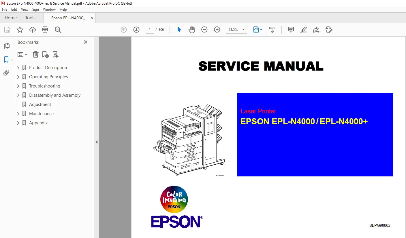
This manual describes basic functions, theory of electrical and mechanical operations, maintenance and repair procedures of EPL-N4000/N4000+.
The instructions and procedures included herein are intended for the experienced repair technicians, and attention should be given to the precautions
on the preceding page.
Safety Information
- To prevent accidents during a maintenance procedure, strictly observe the Warnings and Cautions. Do not do anything that is dangerous or not within the scope of this document.
- Do not do anything that is dangerous even if not specifically described in this manual. In addition to the descriptions below and those given in this manual, there are many situations and circumstances that are dangerous. Be aware of these when you are working with the printer
TABLE OF CONTENTS:
Epson EPL-N4000_4000 Service Manual – PDF DOWNLOAD
Product Description 15
11 Features 16
12 Changes from EPL-N4000 to EPL-N4000+ 19
13 Basic Specification 22
131 Controller Specification 22
132 Engine Specification 23
133 Paper Specification 24
134 Electrical Specification 26
135 Reliability, Durability and Maintainability 27
136 Safety Approval 29
137 Environmental Specification 30
1371 Operating Environment(including optional parts) 30
1372 Storage Environment(including optional parts) 30
1373 Altitude 30
1374 Vibration Tolerance 30
138 External Dimension and weight 31
139 Other Specifications 32
1310 Consumables 32
1311 Configuration 32
1312 Host Interface Specification 33
13121 Parallel Interface 33
13122 Ethernet Interface Specification 34
13123 Type-B Interface 36
14 OPERATION 37
141 Control Panel 37
1411 Status Sheet 40
142 Panel Setting Mode 40
1421 One Touch Setting Mode 40
1422 List of Setting Items 41
1423 Description of Setting Item and Model-dependent 49
1424 Printing Menu 50
143 User setting items not included in the setting menu 57
144 Special Operation Functions 58
145 Maintenance Mode 60
1451 Operation 60
146 Engine Status Sheet 61
147 Initialization Process 65
Operating Principles 66
21 Mechanical Drive 67
211 Overview 67
212 Mechanical Drive Component 67
2121 Offset Motor 68
2122 Main Motor and Main Drive Assembly 68
2123 Lift Up Motor 1 and Lift Up Motor 2 69
2124 Motor Control 69
22 Paper Path 70
221 Paper Path Components 71
222 Paper Feed, Transport and Paper Eject Drive 73
223 Mechanical drive for paper fed from the MSI 73
224 Mechanical Drive for Paper Fed from Tray1 74
225 Mechanical Drive for Paper Fed from Tray2 74
226 Mechanical Drive for Registration 75
227 Mechanical Drive for the Drum and BTR 75
228 Mechanical Drive for the Fuser 76
229 Mechanical Drive for Exit Drive 76
2210 Mechanical Drive for Offset 77
2211 Paper Path Component Control 77
23 ROS (Raster Output Scanner) 78
231 ROS Components 78
2311 Housed inside the ROS Assembly 78
232 ROS Operation 79
2321 Image Resolution 80
2322 ROS Control 80
24 Print Process 82
241 Charge 83
242 Exposure 84
243 Develop 85
244 Transfer 86
245 Detack 86
246 Fusing 87
247 Clean 87
25 Print Sequence 88
26 Operating Principles for Power Supply Circuit 90
261 Power Supply Circuit 90
262 Power Supply Components 90
27 Printer Control 93
271 Printer Control Components 95
2711 Machine Control Unit PWB (MCU PWB) 95
2712 Components attached to or associated with the MCU PWB: 95
2713 Function of the MCU during printer control 99
272 Controller101
2721 Functions of the Controller101
2722 Specification on the Controller101
Troubleshooting103
31 Troubleshooting104
311 Service Flowchart104
312 FIP Flowchart105
3121 How to use the FIP Flowchart105
3122 How to follow a FIP106
3123 General Notes on Using FIPs106
32 Printer Message108
321 Printer Message110
322 Service Req Error113
3221 Engine Error113
3222 Controller Error113
323 Operation when Service Req Error Occurs114
33 Printer Performance Problems(not indicated by Error Codes)115
331 Inoperative Printer115
332 Erratic Operation117
333 Inoperative Control Panel118
334 Inoperative Main Drive Assembly119
335 Inoperative Paper Feed Drive121
336 J1-2 is not displayed when the EP Cartridge is out of toner122
337 Inoperative Interlock Switch122
338 Inoperative Offset123
34 Image Quality FIPs124
341 Light(Undertoned) Prints125
342 Blank White127
343 Black Prints128
344 Vertical Band Deletions130
345 Horizontal Band Deletions131
346 Vertical Streaks132
347 Horizontal Streaks133
348 Spot Deletions135
349 Spots136
3410 Residual Image or Ghosting138
3411 Background139
3412 Skewed Image141
3413 Damaged Prints142
3414 Unfused Image or Image Easily Rubbed Off143
3415 Image not Registered Correctly143
35 Secondary FIPs144
Disassembly and Assembly146
41 Overview147
411 Cautions before starting147
412 Tools147
413 Notations in the Manual147
42 Procedures for Disassembling149
421 Fuser Full Cover152
4211 Removal152
4212 Installation152
422 Top Cover Assembly153
4221 Removal153
4222 Installation153
423 Rear Cover Assembly154
4231 Removal154
4232 Installation154
424 Right Cover155
4241 Removal155
4242 Installation155
425 Control Panel156
4251 Removal156
4252 Installation156
426 Rear Cover 1TM157
4261 Removal157
4262 Installation157
427 Tray 1 Lift Up Motor158
4271 Removal158
4272 Installation158
428 Tray 1 Feed Clutch159
4281 Removal159
4282 Installation159
429 Feed, Nudger, and Retard Rolls160
4291 Removal160
4292 Installation160
4210 Tray1 Take Away Roll Assembly161
42101 Removal161
42102 Installation162
4211 Tray 1 Feeder Assembly164
42111 Removal164
42112 Installation165
4212 Support Assembly Spring166
42121 Removal166
42122 Installation166
4213 Tray1 Retard Assembly167
42131 Removal167
42132 Installation167
4214 Tray 1&2 Front Chute Assemblies169
42141 Removal169
42142 Installation169
4215 Tray 1 & Tray 2 Level Sensors170
42151 Removal170
42152 Installation170
4216 Tray1 & Tray 2 No Paper Sensors171
42161 Removal171
42162 Installation171
4217 Tray 1 & Tray 2 Paper Size Sensors172
42171 Removal172
42172 Installation172
4218 Tray 2 Feed Clutch173
42181 Removal173
42182 Installation173
4219 Tray 2 Feeder Assembly174
42191 Removal174
42192 Installation175
4220 Tray2 Take Away Roll Assembly176
42201 Removal176
42202 Installation176
4221 Tray 2 Retard Assembly177
42211 Removal177
42212 Installation177
4222 MSI Feeder Assembly (Manual Feeder)178
42221 Removal178
42222 Installation178
4223 MSI Tray Assembly178
42231 Removal178
42232 Installation179
4224 MSI Support Assembly180
42241 Removal180
42242 Installation180
4225 MSI Size Sensor Assembly181
42251 Removal181
42252 Installation182
4226 MSI Feed Clutch183
42261 Removal183
42262 Installation185
4227 MSI Feed Roll186
42271 Removal186
42272 Installation186
4228 MSI Nudger Roll187
42281 Removal187
42282 Installation187
4229 MSI Nudger Roll Assembly188
42291 Removal188
42292 Installation188
4230 MSI Pad189
42301 Removal189
42302 Installation189
4231 MSI Friction Clutch190
42311 Removal190
42312 Installation190
4232 MSI No-Paper Sensor Assembly191
42321 Removal191
42322 Installation191
4233 L/H Low Cover Assembly192
42331 Removal192
42332 Installation193
4234 Left Lower Cover Assembly194
42341 Removal194
42342 Installation194
4235 Left Lower Cover Pinch Roll Assembly195
42351 Removal195
42352 Installation195
4236 Left Lower Cover Interlock Switch196
42361 Removal196
42362 Installation196
4237 Tray 2 Take Away Sensor197
42371 Removal197
42372 Installation197
4238 Registration Clutch198
42381 Removal198
42382 Installation198
4239 Left Upper Cover Assembly199
42391 Removal199
42392 Installation200
4240 Left Chute Assembly201
42401 Removal201
42402 Installation201
4241 Registration Chute Assembly202
42411 Removal202
42412 Installation202
4242 Registration Roll Assembly203
42421 Removal203
42422 Installation203
4243 Registration Sensor204
42431 Installation204
42432 Installation204
4244 ROS Assembly205
42441 Removal205
42442 Installation205
4245 EP Cartridge (Toner Cartridge)206
42451 Removal206
42452 Installation206
4246 BTR Assembly (Transfer roller unit)208
42461 Removal208
42462 Installation208
4247 Toner Sensor209
42471 Removal209
42472 Installation209
4248 CRU Interlock Switch210
42481 Removal210
42482 Installation210
4249 Fuser Assembly211
42491 Removal211
42492 Installation211
4250 Fuser Drive Assembly212
42501 Removal212
42502 Installation213
4251 Offset/Exit Assembly214
42511 Removal214
42512 Installation214
4252 Exit Drive Assembly215
42521 Removal215
42522 Installation215
4253 Exit Gate Solenoid216
42531 Removal216
42532 Installation216
4254 Offset Motor217
42541 Removal217
42542 Installation217
4255 Face Up Exit Sensor218
42551 Removal218
42552 Installation218
4256 Offset Roller Assembly219
42561 Removal219
42562 Installation219
4257 Lower Chute Assembly220
42571 Removal220
42572 Installation220
4258 Upper Chute Assembly221
42581 Removal221
42582 Installation221
4259 Exit Roll Assembly222
42591 Removal222
42592 Installation222
4260 Full Stack Sensor223
42601 Removal223
42602 Installation223
4261 Inverter Clutches224
42611 Removal224
42612 Installation224
4262 Main Drive Assembly225
42621 Removal225
42622 Installation227
4263 Main Power Switch228
42631 Removal228
42632 Installation228
4264 Low Voltage Power Supply(LVPS) Assembly229
42641 Removal229
42642 Installation229
4265 AC Driver PWB230
42651 Removal230
42652 Installation230
4266 High Voltage Power Supply(HVPS) Assembly231
42661 Removal231
42662 Installation231
4267 Noise Filter PWB232
42671 Removal232
42672 Installation232
4268 Left Cover Interlock Switch Assembly233
42681 Removal233
42682 Installation233
4269 MCU(Machine Control Unit) PWB234
42691 Removal234
42692 Installation235
4270 Controller Board236
42701 Removal236
4271 ESS Box237
42711 Removal237
42712 Installation237
Adjustment238
Maintenance240
61 Maintenance241
611 Exchange Units and Parts by User241
Appendix242
71 Connector Pin Diagram243
711 Pin Alighnment243
712 How to use P/J location Table and Map245
713 Signal Information253
72 Board Component Layout265
721 C262 Main Board Component265
73 Parts List267
731 Top Cover Assembly267
732 Front Cover268
733 Rear, Left and Right Cover269
734 Tray Unit – Paper Stack270
735 Tray Unit – End Guide271
736 Tray Interface -Tray 1272
737 Paper Pick Up – Tray 1273
738 Retard and Take Away-Tray 1274
739 Tray Interface-Tray 2275
7310 Paper Pick Up-Tray 2276
7311 Retard and Take Away- Tray 2277
7312 Feed Drive Transmission278
7313 Multi Sheet Inserter and MSI/Duplex Support279
7314 MSI Feeder Assembly280
7315 Upper Feeder Assembly281
7316 MSI Tray Assembly282
7317 Tray 1 Frame and Left Cover283
7318 Tray 2 Frame and Left Cover284
7319 Registration285
7320 Left Upper Cover Assembly286
7321 Transport Chute Assembly287
7322 ROS Assembly288
7323 Xerography and Development289
7324 Fuser Assembly290
7325 Exit Lower Chute291
7326 Offset Roller292
7327 Exit Upper Chute Assembly293
7328 Exit Drive Assembly294
7329 Main Drive Assembly295
7330 Fuser Drive Assembly296
7331 Power Inlet and LVPS297
7332 HVPS and MCU PWB298
7333 Controller Assembly299
S.M 26/2/2025