

DOOSAN SOLOR EXCAVATOR PARTS MANUAL 2021-7144BEF – PDF DOWNLOAD
DESCRIPTION:
DOOSAN SOLOR EXCAVATOR PARTS MANUAL 2021-7144BEF – PDF DOWNLOAD
- Daewoo reserves the right to improve our products in a continuing process to provide the best possible product to the marketplace. These improvements can be implemented at any time with no obligation to change materials on previously sold products.
- It is recommended that consumers periodically contact their distributors for recent documentation on purchased equipment. This documentation may include attachments and optional equipment that is not available in your machine’s package.
- Please call your distributor for additional items that you may require. Illustrations used throughout this manual are used only as a representation of the actual piece of equipment, and may vary from the actual item
FOREWORD
This parts list is shown the equipment components parts of roAEWOO EXCAVATOR S01 OJ
1. HOW TO ORDER PARTS.
When ordering parts, please specify the follwing items as shown in the following example.
Ex. 1) Model of Machine S010 (Shown on name plate on the side cover)
2) Machine Serial No HESN0-0000 (Shown on nameplate on the bed frame)
3) Engine Serial No YANMAR ENGINE (Shown on Engine cylinder block)
4) Part No. 2401-9170
5) Description
6) Q’ty
TRAVEL MOTOR
2. HOW TO USE THIS PARTS LIST.
Key No.
Part No.
Description
It shows the reference no. on the illustration.
It shows the part number of the parts which are included in an illustration.
It shows the name of part. Components of an assembly part are shown with
[e] marks and are shown on the line, or lines, below the assembly part.
Q’ty
Also if the components with [ •] mark is consists of further components part.
These further components are shown with the marks [ee].
It shows the quantity use for one machine. quantity of components show the
quantity for one assembly part.
Service code Abbreviations in this column have their own meaning as show below.
The parts with this abbreviation shows that the part requires some
work on it before instatling in the machine.
B
D The part with this abbreviation is a component of an assembly and
is not available independently. The assembly part containing this
part should be ordered.
K This means that the part is contained in the service part kit.
M This means that the part is available only with its mating parts altogether.
A The part with this abbreviation shows that the quantity of the part
is changed depending on the machine. such as an adjusting shim etc.
S This part is specially provided as a service part. which was not
provided in the machine before shipping from the factory.
G This part need grade control and should be requested as the same
grade of counter part.
OP Optional parts.
(THIS PARTS BOOK IS F
TABLE OF CONTENTS:
DOOSAN SOLOR EXCAVATOR PARTS MANUAL 2021-7144BEF – PDF DOWNLOAD
ENGINE PARTS
Fig. 100 CYLINDER BLOCK BLOC CYLINDRE 2
110 TIMING GEAR HOUSING CARTER DE DISTRIBUTION 4
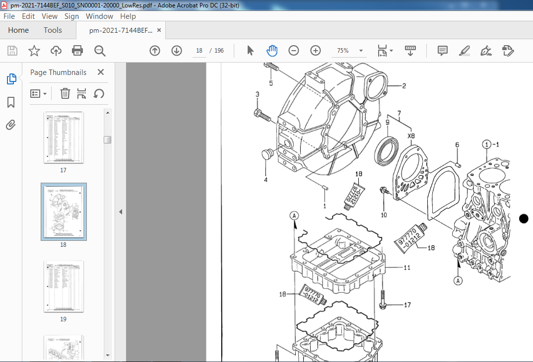
120 FLYWHEEL HOUSING & OIL PUMP CARTER DE VOLANT MOTEUR & POMPE A HUILE 6
130 CYLINDER HEAD & COVER CULLASSE & COUVERCLE 8
140 SUCTION MANIFOLD & AIR CLEANER SUCTION TUBULURE & FILTRE A AIR 12
150 EXHAUST MANIFOLD & MUFFLER POT D’ECHAPPEMENT & SILENCIEUX 14
160 CAMSHAFT & DRIVING GEAR ARBRE A CAMES & PIGNON 16
170 CRANKSHAFT & PISTON VILEBREQUIN & PISTON 18
180 OIL SYSTEM SYSTEME DE HUILE 20
190 COOLING SYSTEM SYSTEME DE REFROIDISSMENT 22
200 FUEL INJECTION PUMP INJECTEUR DE GAZOLE 24
210 GOVERNOR GOUVERNEUR 28
220 FUEL INJECTION NOZZLE INJECTEUR ET PORTE-INJECTEUR
34
230 STARTING MOTOR DEMARREUR
38
240 GEN ELA TOR GENELATEUR
40
250 GASKET SET JOINT POSER
42
e BODY PARTS
Fig. 1100 TRACK ASS’Y-WIDTH 900mm ENSEMBLE TRAIN DE ROULEMENT 44
1110 TRACK PIPING CONDUITES DE TRANSLATION 46
1120 BLADE-1100mm DOZER 48
2100 SWING BODY ORIENTATION CORPS 50
2110 ENGINE MOUNTING ENSEMBLE MOTEUR 52
2120 FUEL TANK RESERVOIR A GAZOLE 54
2130 OIL TANK RESERVOIR D’HUILE 56
2140 LOW PIPING CONDUITES REFROIDSSEMENT 58
2150 MAIN PIPING CIRCUIT HYDRAULIQUE PRINCIPAL 60
2160 GREASE PIPING GRAISSE CONDUITES 62
2170 LEVER ASS’Y ( 1) ENSEMBLE LEVIER 64
2180 LEVER ASS’Y (2) ENSEMBLE LEVIER 66
2190 CONTROL STAND CONSOLE 70
2200 BONNET CAPOT 72
2210 SPONGE ASS’Y ENSEMBLE EPONGE 74
2220 PUMP DRIVE CHASSER POMPE 76
2230 ELECTRIC PARTS ( l) EQUIPMENT ELECTRIQUE
78
2240 ELECTRIC p~R’TIJ~JPARTS BOOK 1~5g’5J1J~f§_~§N@Bf9
2250 ENGINE CONTROL LEVER COMMANDE REGIME MOTEUR 82
2260 FUEL PIPING CONDUITES A GAZOLE 84
e FRONT PARTS – Fig. 3100 FRONT FRONT ALES 86
3110 BUCKET-0.35M3 GODET 88
3120 BOOM SWING ASS’Y ENSEMBLE ORIENTATION FLECHE 90
3130 FRONT PIPING CONDUITES FRONTALES 92
e OTHER PARTS
Fig. 4100 NAME PLATE-DOMESTIC O:j ~ .3::: ‘/;! n 94 0 q
4110 NAME PLATE-ENGLISH PLAQUE D’IDENTIFICATION 96
4115 NAME PLATE-EUROPE PLAQUE D’IDENTIFICATION 97-1
4120 TOOLS OUTILES 98
4130 SPARE PARTS PIECES DE RECHANGE 100
e OPTION PARTS
Fig. 5100 TRACK ASS’Y-EXPORT WIDTH 810mm ENSEMBLE TRAIN DE ROULEMENT 102
5110 TRACK PIPING-EXPORT CONDUITES DE TRANSLATION 104
5120 BLADE-EXPORT 810mm DOZER 106
5130 BREAKER PIPING-ONE WAY CANALISATION DE FREIN 107-1 – 5140 OPTION PIPING-TWO WAY CANALISATION DE FREIN 107-3
5150 FUEL PIPING-SEDIMENTER CONDUITES A GAZOLE 107-5
e HYDRAULIC COMPONENTS
Fig. 6100 BOOM CYLINDER VERIN DE FLECHE
108
6110 ARM CYLINDER YERIN DE BALANCIER 110
6120 BUCKET CYLINDER YERIN DE GODET 112
6130 BOOM SWING CYLINDER YERIN ORIENTATION FLECHE 114
6140 DOZER CYLINDER YERIN DE BLADE 116
6150 SWING DEVICE SYSTEME D’ORIENTATION 118
6160 TRA YEL DEVICE SYSTEME D’TRANSLATION 122
6170 MAIN PUMP POMPE 126
6180 CONTROL VAL YE DISTRIBUTEUR 128
6190 INLET BODY ASS’Y TIROIRS DE COMMANDE 130
6200 WORK BODY ASS’Y-BUCKET TIROIRS DE COMMANDE 132
6210 WORK BODY ASS’Y-BOOM TIROIRS DE COMMANDE 134
6220 WORK BODY ASS’Y-BOOM SWING TIROIRS DE COMMANDE 136
6230 WORK BODY ASS’Y-TRAYEL TIROIRS DE COMMANDE 138
6240 WORK BODY ASS’Y-DOZER TIROIRS DE COMMANDE 140
6250 WORK BO[ft~~~TS BOOK 1sT\R@[~~~
6260 WORK BODY ASS’Y-ARM TIROIRS DE COMMANDE
6270 WORK BODY ASS’Y-SWING TIROIRS DE COMMANDE
6280 INLET BODY ASS’Y TIROIRS DE COMMANDE
6290 RELIEF VAL VE ASS’Y TIROIRS DE COMMANDE
6300 O/L RELIEF VAL VE ASS’Y TIROIRS DE COMMANDE
6310 O/L RELIEF VALVE ASS’Y TIROIRS DE COMMANDE
6320 ROTARY JOINT JOINT ROTATOIRE
VIDEO PREVIEW OF THE MANUAL:

IMAGES PREVIEW OF THE MANUAL:

PLEASE NOTE:
- This is not a physical manual but a digital manual – meaning no physical copy will be couriered to you. The manual can be yours in the next 2 mins as once you make the payment, you will be directed to the download page IMMEDIATELY.
- This is the same manual used by the dealers inorder to diagnose your vehicle of its faults.
- Require some other service manual or have any queries: please WRITE to us at [email protected]
S.M


