

Doosan Daewoo Solar 470lc v Excavator Full Service Manual
FILE DETAILS:
LANGUAGE:ENGLISH
PAGES:601
DOWNLOADABLE:YES
FILE TYPE:PDF
VIDEO PREVIEW OF THE MANUAL:

IMAGES PREVIEW OF THE MANUAL:
DESCRIPTION:
Doosan Daewoo Solar 470lc v Excavator Full Service Manual
GENERAL SAFETY ESSENTIALS
ACCESSORY APPLICATIONS
The excavator has been primarily designed for moving earth with a bucket. For use as a grapple or for other object handling, contact Daewoo for proper installation and application. Lifting-work applications (unless restricted or prohibited by local regulations) are permitted in approved lift configuration, to rated capacity only, with no side-loading. DO NOT use the machine for activities for which it was not intended. DO NOT use the bucket for lifting work, unless lift slings are used in the approved configuration. Use of an accessory hydraulic hammer (breaker), work in rough terrain, demolition applications or other hazardous operation may require installation of additional protective structures to safeguard the operator.
LIFTING CAPACITY RATING CONFIGURATION
Lifting capacity ratings that are printed at the end of this safety section are based on the machine being level, on a firm supporting surface, with hooks and slings attached in approved configuration. Loads must be balanced and supported evenly. Use taglines to keep the load steady if wind conditions and large surface area are a problem. Work crew hand signals, individual tasks and safe procedures should all be universally understood before the lift is made.
TABLE OF CONTENTS:
Doosan Daewoo Solar 470lc v Excavator Full Service Manual
To the Operator of a Daewoo Excavator 3
General Safety Essentials 5
Location of Safety Labels 5
Summary of Safety Precautions for Lifting in Digging Mode 6
Work-site Precautions 7
Operation 9
Equipment 14
Maintenance 18
Shipping and Transportation 21
Lifting With Sling 21
General Description 3
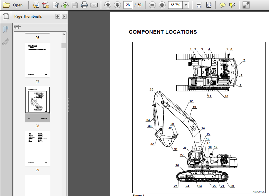
Component Locations 4
General Dimensions 7
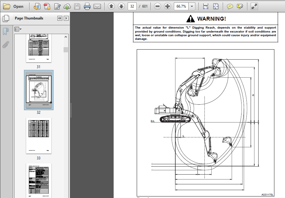
Working Range 8
General Specifications 10
Engine Performance Curves (Per Ks-r1004 Standard) 12
Approximate Weight Of Workload Materials 14
Performance Tests 17
Excavator Performance Standards 18
Test Conditions 18
Travel Speed and Travel Motor Balance (Steering Deviation) Tests 18
Cylinder Performance Tests 21
Welding Precautions and Guidelines 3
Hydraulic System – General Precautions 4
Maintenance Service and Repair Procedure 5
General Precautions 5
Hydraulic System Cleanliness and Oil Leaks 6
Maintenance Precautions for Hydraulic System Service 6
Oil Leakage Precautions 6
Cleaning and Inspection 7
General Guidelines 7
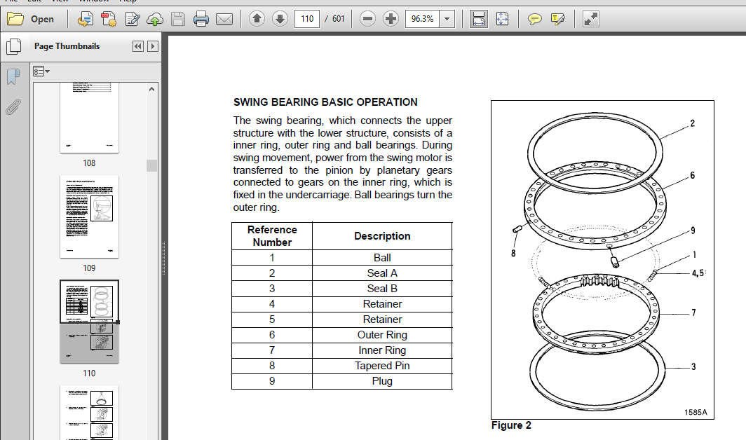
Bearing inspection 8
Removal 3
Installation 6
General Description 3
Track Tension 3
Cleaning and Inspection (Wear Limits and Tolerances) 5
Track Shoes and Links 9
Parts List 9
Track Removal 10
Track Installation 11
Front Idler Roller 12
Parts List 12
Front Idler Roller 13
Parts List 13
Front Idler Roller Disassembly 14
Front Idler Roller Reassembly 16
Lower Roller 17
Lower Roller 18
Parts List 18
Lower Roller Removal 19
Lower Roller Disassembly 19
Lower Roller Reassembly 20
Lower Roller Installation 21
Upper Roller 22
Parts List 22
Upper Roller 24
Parts List 24
Upper Roller Removal 25
Upper Roller Disassembly 25
Upper Roller Reassembly 27
Track Spring and Track Adjusting Cylinder 29
Parts List 29
Track Spring and Track Adjusting Cylinder 30
Parts List 30
Refrigerant Circulation 3
Control Panel 5
Control Specifications 6
Temperature Level Control and Display 7
Air Discharge According to Path Selection 8
Air-conditioning System Circuit Diagram 10
Troubleshooting 12
Refrigerant System Repairs 15
Refrigerant Safe Handling Procedures 15
Repair and Replacement Procedure 16
Refrigerant Recovery 18
Vacuuming Refrigerant System 18
Leakage Check 19
Refrigerant Charging 20
Inspecting System For Leakage 22
Hydraulic System – General Notes 4
Hydraulic Schematic 5
General Notes 5
Operation of Working Components 6
Boom Operating Circuit 6
Boom Up Circuit 6
Boom Down Circuit 6
Arm Operating Circuit 7
Arm Crowd Circuit 7
Arm Dump Circuit 7
Bucket Operating Circuit 8
Bucket Crowd Circuit 8
Bucket Dump Circuit 8
Swing Operating Circuit 8
Right Swing Operating Circuit 9
Left Swing Operating Circuit 9
Swing Relief Valve and Make-up Valve 9
Travel Operating Circuit 9
Forward Travel Circuit 10
Reverse Travel Circuit 10
Procedural Troubleshooting Baseline Recommendations 11
Initial Checks and Tests to Establish Operating Condition of the Excavator
11
Pilot Pressure 12
Adjustment and Testing 12
Power Mode Valve 13
Current Signal and Hydraulic Pressure Adjustments 13
Boom/Front Priority Valve 14
Control Valve Pressure and Current Adjustments 14
Pressure Up Valve 15
Checks and Adjustments 15
Pump Input Power Control 17
Page 3
Hydraulic System Troubleshooting, Testing and
Adjustment
Return to Master Table of Contents
Pump Regulator Adjustment 17
Flow Meter and Flow Meter Kit Installation and Testing 20
Swing System Troubleshooting 22
Precautions/Initial Checks 22
Swing Relief Valve Checking and Adjustment 22
Troubleshooting – Swing Gearbox 24
Troubleshooting – Hydraulic Problems 25
Troubleshooting – Control Valve 27
Troubleshooting – Travel Control Valve 28
Troubleshooting – Joystick Control Valve 29
Troubleshooting – Electrical System 4
Overview 5
Electric Supply System 6
Engine Starting Circuit 7
Operation During Start Process 7
Operation After Start Process 8
Engine Preheating System 9
Engine Stop System 10
Charging System 13
Monitoring System 14
Instrument Panel 15
Monitoring System Schematic 16
Operation 18
Instruments 18
Warning and Indicator Lights 20
Initial Operation 22
Mode Select Switch 23
Graphic Information Area Display 24
Overview 24
Main Menus for the Graphic Display Area 25
Menu Selection Buttons 25
Main Menu 26
Language setting 26
Time Setting 26
Filter/Oil information 27
Special Menu 28
Entering/Accessing and Exiting/Escaping Menus 28
Special Menu Selections 29
Electronic Hydraulic Control System (e-EPOS) 42
Control System Schematic 42
Power Mode Control 44
S0802220K
Page 3
Electrical System
Operation 45
Power Mode Control – Circuit Diagram 48
Trenching Mode Control 50
Operation 51
Trenching Mode Control – Circuit Diagram 52
Engine Control System 53
Engine Control Motor 54
Engine Control Dial 55
Engine Control Circuit Diagram 57
Automatic Deceleration Control (Auto Idle Control) 58
Engine Overheat Protection System 59
Power Boost Mode 60
Operation 60
Power Boost Control – Circuit Diagram 61
Automatic Travel Speed Control 62
Automatic Travel Speed Control – Circuit Diagram 63
Engine Control Device – Adjustment 64
Self-diagnostic Function 67
e-EPOS Controller 67
Engine Throttle Controller 69
Wiper System 70
Wiper Circuit 70
Wiper Operation 70
Window Washer Operation 71
Lighting System 72
Lighting System Circuit Diagram 72
Kind of Light 73
Operation 73
Overload Warning Device 74
Overload Warning Device Circuit Diagram 74
Front Attachment Pin Specifications 3
Front Attachment – Removal and Installation 4
Arm Removal Procedure 4
Boom Removal Procedure 6
Installation 7
Arm Installation Procedure 7
Boom Installation Procedure 7
Start-up Procedures 8
PLEASE NOTE:
- This is the same manual used by the dealers to diagnose and troubleshoot your vehicle
- You will be directed to the download page as soon as the purchase is completed. The whole payment and downloading process will take anywhere between 2-5 minutes
- Need any other service / repair / parts manual, please feel free to contact [email protected] . We still have 50,000 manuals unlisted


