

DEUTZ-FAHR AGROCOMPACT F60 70F3 70F4 F80 F90 Workshop Manual – PDF DOWNLOAD
FILE DETAILS:
DEUTZ-FAHR AGROCOMPACT F60 70F3 70F4 F80 F90 Workshop Manual – PDF DOWNLOAD
Language : English
Pages : 520
Downloadable : Yes
File Type : PDF
Size: 22.5 MB
IMAGES PREVIEW OF THE MANUAL:
VIDEO PREVIEW OF THE MANUAL:
DESCRIPTION:
DEUTZ-FAHR AGROCOMPACT F60 70F3 70F4 F80 F90 Workshop Manual – PDF DOWNLOAD
introduction:
This publication is intended for the trained technician who must operate on our tractors.
It contains all general information relating to our tractor range, and in particular it highlights the inspection, overhauling
and adjustment procedures as well as the main instructions for dismantling and reassembling operations.
The workshop manual is a natural summary for the mechanic who has attended the vocational training and specialization
courses, which are held every year at our Service School, to permit him to perform a precise and qualified work on
tractor.
Its contents are therefore an exhaustive reference book for the experienced mechanic who desires to refresh his memory
on the sequence of the operations to be done. It is then good practice for every authorized dealer mechanic to
have at his disposal this publication, so that it may be consulted quickly when necessary.
We wish to thank in advance for the cooperation all thos people, who will let us have their suggestions in order to make
this publication more complete.
TABLE OF CONTENTS:
DEUTZ-FAHR AGROCOMPACT F60 70F3 70F4 F80 F90 Workshop Manual – PDF DOWNLOAD
307.1069.3.6 AGROCOMPACT F60-F70-F80-F90…………………………………………………………………………………………. 1
introduction………………………………………………………………………………………………………………. 1
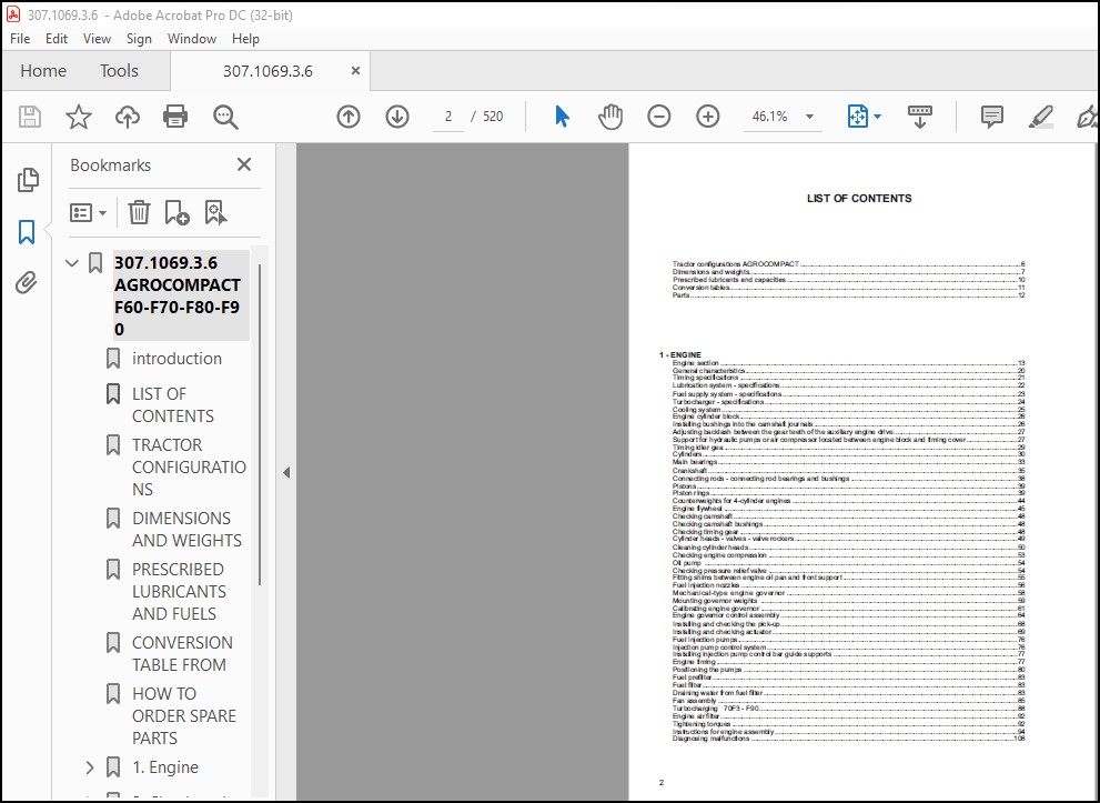
LIST OF CONTENTS…………………………………………………………………………………………………………… 2
TRACTOR CONFIGURATIONS……………………………………………………………………………………………………… 7
DIMENSIONS AND WEIGHTS……………………………………………………………………………………………………… 8
PRESCRIBED LUBRICANTS AND FUELS……………………………………………………………………………………………… 10
CONVERSION TABLE FROM………………………………………………………………………………………………………. 11
HOW TO ORDER SPARE PARTS……………………………………………………………………………………………………. 12
1. Engine…………………………………………………………………………………………………………………. 13
Engine section…………………………………………………………………………………………………………. 13
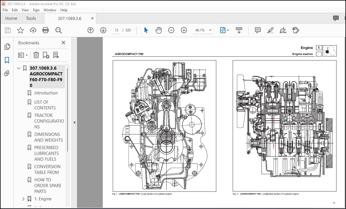
AGROCOMPACT F60 – Cross section of 3-cylinder engine……………………………………………………………………. 13
AGROCOMPACT F60 – Longitudinal section of 3-cylinder engine……………………………………………………………… 13
AGROCOMPACT 70F3 – Cross section of 3-cylinder TURBO engine……………………………………………………………… 14
AGROCOMPACT 70F3 – Longitudinal section of 3-cylinder TURBO engine……………………………………………………….. 15
AGROCOMPACT 70F4 – AGROCOMPACT F80 – Cross section of 4-cylinder engine…………………………………………………… 16
AGROCOMPACT 70F4 – AGROCOMPACT F80 – Longitudinal section of 4-cylinder engine…………………………………………….. 17
AGROCOMPACT F90 – Cross section of 4-cylinder TURBO engine………………………………………………………………. 18
AGROCOMPACT F90 – Longitudinal section of 4-cylinder TURBO engine………………………………………………………… 19
General information…………………………………………………………………………………………………….. 20
Timing specification……………………………………………………………………………………………………. 21
Lubrication system – specifications………………………………………………………………………………………. 22
Fuel system – specifications…………………………………………………………………………………………….. 23
Turbocharging – specifications…………………………………………………………………………………………… 24
Cooling system – specifications………………………………………………………………………………………….. 25
Timing case……………………………………………………………………………………………………………. 26
Engine cylinder block……………………………………………………………………………………………….. 26
Installing bushings into the camshaft journals…………………………………………………………………………. 26
Adjusting backlash between the gear teeth of the auxiliary engine drive…………………………………………………… 27
Support for hydraulic pumps or air compressor located between engine block and timing cover…………………………………. 27
Auxiliary drive for either hydraulic pumps or air compressors……………………………………………………………. 28
Cylinder block…………………………………………………………………………………………………………. 29
Cylinder………………………………………………………………………………………………………………. 30
Cylinder 1000-W………………………………………………………………………………………………………… 32
Crankshaft…………………………………………………………………………………………………………….. 33
Main bearings………………………………………………………………………………………………………. 33
Crankshaft assembly – 3-cylinder engine……………………………………………………………………………….. 34
Crankshaft assembly – 4-cylinder engine……………………………………………………………………………….. 34
Crankshaft…………………………………………………………………………………………………………. 35
Checking crankshaft…………………………………………………………………………………………………. 36
Checking crankshaft journal out-of-roundness and tape…………………………………………………………………… 36
Checking main bearings………………………………………………………………………………………………. 36
Mounting main bearing caps…………………………………………………………………………………………… 36
Cleaning crankshaft and cylinder block internal passages………………………………………………………………… 37
Checking crankshaft end play…………………………………………………………………………………………. 37
Connecting rods – connecting rod bearings and bushings………………………………………………………………….. 38
pistons – gudgeon pins – piston rings…………………………………………………………………………………. 39
Pistons……………………………………………………………………………………………………………. 39
Piston rings……………………………………………………………………………………………………….. 39
Pistons. A – naturally aspirated engines B – turbo engines………………………………………………………………. 40
Instructions for fitting piston rings to pistons. A – naturally aspirated engines B – turbo engines………………………….. 41
Cleaning pistons……………………………………………………………………………………………………. 42
Checking pistons……………………………………………………………………………………………………. 42
Checking gudgeon pin and gudgeon pin seat in piston…………………………………………………………………….. 42
Checking piston ring end gap…………………………………………………………………………………………. 42
Checking clearance between piston rings and piston ring grooves in piston…………………………………………………. 43
Installing piston rings……………………………………………………………………………………………… 43
Installing pistons into cylinders…………………………………………………………………………………….. 43
Counterweights for 4-cylinder engines…………………………………………………………………………………. 44
Engine flywheel…………………………………………………………………………………………………….. 45
Checks…………………………………………………………………………………………………………….. 45
Crankshaft removal procedure…………………………………………………………………………………………. 46
Camshaft………………………………………………………………………………………………………………. 47
Checking camshaft…………………………………………………………………………………………………… 48
Checking camshaft bushings…………………………………………………………………………………………… 48
Checking timing gear………………………………………………………………………………………………… 48
Cylinder head………………………………………………………………………………………………………….. 49
Cylinder heads – valves – valve rockers……………………………………………………………………………….. 49
Cleaning cylinder heads……………………………………………………………………………………………… 51
Checking valve seats………………………………………………………………………………………………… 51
Checking valves…………………………………………………………………………………………………….. 51
Testing valve tightness……………………………………………………………………………………………… 51
Checking valve guides……………………………………………………………………………………………….. 51
Checking push rods………………………………………………………………………………………………….. 52
Checking valve springs………………………………………………………………………………………………. 52
Checking rocker arms………………………………………………………………………………………………… 52
Adjusting valve clearance……………………………………………………………………………………………. 52
Installing cylinder heads……………………………………………………………………………………………. 53
Checking engine compression………………………………………………………………………………………….. 53
Lubrication system……………………………………………………………………………………………………… 54
Oil pump…………………………………………………………………………………………………………… 54
Checking pressure relief valve……………………………………………………………………………………….. 54
Fitting shims between engine oil pan and front support………………………………………………………………….. 55
Fuel system……………………………………………………………………………………………………………. 56
Fuel injection nozzles………………………………………………………………………………………………. 56
MECHANICAL-TYPE ENGINE GOVERNOR………………………………………………………………………………………. 58
RELECTRONIC ENGINE GOVERNOR………………………………………………………………………………………….. 66
DIAGNOSING MALFUNCTIONS……………………………………………………………………………………………… 74
Setting the maximum speed to 30 km/h………………………………………………………………………………….. 75
Fuel injection pumps………………………………………………………………………………………………… 76
Injection pump control system………………………………………………………………………………………… 76
Installing injection pump control bar guide supports……………………………………………………………………. 76
Engine timing………………………………………………………………………………………………………. 77
Installing the injection pumps……………………………………………………………………………………….. 79
Positioning the pumps……………………………………………………………………………………………….. 80
Fuel prefilter……………………………………………………………………………………………………… 83
Fuel filter………………………………………………………………………………………………………… 83
Draining water from fuel filter………………………………………………………………………………………. 83
Checking the fuel supply pump efficiency (A.C. pump)……………………………………………………………………. 84
Bleeding the air from the fuel supply system…………………………………………………………………………… 84
Cooling system…………………………………………………………………………………………………………. 85
Water radiator……………………………………………………………………………………………………… 85
Fan……………………………………………………………………………………………………………….. 86
Driving belts………………………………………………………………………………………………………. 86
Thermostat…………………………………………………………………………………………………………. 86
Aligning fan pulley to engine pulley. Both pulleys should be thoroughly aligned……………………………………………. 86
Aligning alternator pulley to engine pulley……………………………………………………………………………. 86
Engine water pump…………………………………………………………………………………………………… 86
Water pump assembly…………………………………………………………………………………………………. 86
ADJUSTING OF DRIVE BELT TENSION FOR ENGINE…………………………………………………………………………….. 87
Intake and exhaust system……………………………………………………………………………………………….. 88
Supercharging 70F3 F90………………………………………………………………………………………………. 88
Tests……………………………………………………………………………………………………………… 88
Checking pressure in the duct at turbocharger exit……………………………………………………………………… 89
Checking exhaust pipes………………………………………………………………………………………………. 89
Removal……………………………………………………………………………………………………………. 89
Checking rotor shaft radial play – turbine side………………………………………………………………………… 90
Checking rotor shaft end play………………………………………………………………………………………… 90
Installing turbocharger on engine…………………………………………………………………………………….. 91
Engine air filter…………………………………………………………………………………………………… 92
Tightening torques………………………………………………………………………………………………….. 92
Engine air filter…………………………………………………………………………………………………… 93
Cleaning with compressed air…………………………………………………………………………………………. 93
Washing with water………………………………………………………………………………………………….. 93
Reassembling the cartridge…………………………………………………………………………………………… 93
Assembly………………………………………………………………………………………………………………. 94
Instructions for engine assembly……………………………………………………………………………………… 94
Reassembling the engine on tractor…………………………………………………………………………………….107
Diagnosing malfunctions………………………………………………………………………………………………….108
2. Clutch and transmission…………………………………………………………………………………………………..110
Clutch…………………………………………………………………………………………………………………110
Gearshift clutch…………………………………………………………………………………………………….110
Spring specifications to Belleville washer for the clutch engagement………………………………………………………110
Clutch unit for F60 – 70F3……………………………………………………………………………………………111
Clutch unit for 70F4 – F80 – F90………………………………………………………………………………………111
Clutch unit for AGROCOMPACT F60 – 70F3 – 70F4 – F80 – F90 (USA) 6 blades…………………………………………………..112
Components of clutch assembly…………………………………………………………………………………………113
Cecking clutch………………………………………………………………………………………………………114
Adjusting clutch control pedal………………………………………………………………………………………..114
Bleeding air from the hydraulic circuit………………………………………………………………………………..114
Stripping the slave cylinder………………………………………………………………………………………….115
Inspections…………………………………………………………………………………………………………115
Notes on refitment…………………………………………………………………………………………………..115
Stripping the master cylinder…………………………………………………………………………………………116
Inspections and checks……………………………………………………………………………………………….117
Reassembly………………………………………………………………………………………………………….117
Diagnosing malfunctions………………………………………………………………………………………………….118
Powershift……………………………………………………………………………………………………………..119
Powershift unit……………………………………………………………………………………………………..119
Diagram illustrating operation of the Powershift system………………………………………………………………….120
Diagram showing engagement of Powershift with MED range selected………………………………………………………….120
Diagram showing engagement of Powershift with LOW range selected………………………………………………………….121
Diagram showing engagement of Powershift with HIGH range selected…………………………………………………………121
POWERSHIFT UNIT DETACH FROM THE GEAR BOX……………………………………………………………………………….122
Powershift unit……………………………………………………………………………………………………..132
Assembly of Powershift unit…………………………………………………………………………………………..133
ADJUSTMENT OF END FLOAT IN THE POWERSHIFT UNIT………………………………………………………………………….137
Fitting the oil manifolds of the Powershift unit………………………………………………………………………..138
Hydraulic diagram illustrating operation……………………………………………………………………………….139
PROCEDURE FOR CHECKING THE H-M-L CONTROL UNIT INLET PRESSURE……………………………………………………………..140
Powershift pressure control valves assembly…………………………………………………………………………….141
Diagnosing malfunctions………………………………………………………………………………………………….142
3. Transmission…………………………………………………………………………………………………………….143
Gearbox………………………………………………………………………………………………………………..143
General specifications……………………………………………………………………………………………….143
Technical specifications……………………………………………………………………………………………..143
Speed change configurations…………………………………………………………………………………………..144
Ratios of 4-speed x 2 range transmission with mini-reduction (16 FWD + 8 REV)………………………………………………145
Ratios of 4-speed x 2 range transmission with mini-reduction and super-reduction (12 FWD + 12 REV)……………………………145
Ratios of 5-speed x 2 range transmission with mini-reduction (20 FWD + 10 REV)……………………………………………..146
Ratios of 5-speed x 2 range transmission with mini-reduction and super-reduction (30 FWD + 15 REV)……………………………146
Ratios of transmission with 3 ranges (Super-reduction) + POWERSHIFT (45 FWD + 45 REV)……………………………………….147
Front and rear gearbox……………………………………………………………………………………………….148
Longitudinal section through transmission………………………………………………………………………………149
Longitudinal section through transmission with Powershift unit……………………………………………………………150
Rear axle longitudinal section………………………………………………………………………………………..151
Rear axle longitudinal section (vigneto version)………………………………………………………………………..152
Gear lever………………………………………………………………………………………………………….153
Views of the gearbox…………………………………………………………………………………………………154
Views of the gearbox…………………………………………………………………………………………………155
Views of the gearbox…………………………………………………………………………………………………156
Electro – hydraulic control for front-wheel drive engagement/disengagement…………………………………………………157
Gear selector rod. A – bolts securing hubs to rod……………………………………………………………………….158
Gear selector rod. B – C – bolts securing hubs to rod……………………………………………………………………158
Range selector rods and forks…………………………………………………………………………………………159
Hydraulic shuttle control…………………………………………………………………………………………….160
REMOVAL AND REFITTING………………………………………………………………………………………………..161
Removal of the rear gearbox without removing the platform (tractors equipped with platform or cab only)……………………161
Dismantling the gearbox…………………………………………………………………………………………..162
Removal of the gearbox input and P.T.O. shafts………………………………………………………………………162
Separating the POWERSHIFT unit from the gearbox……………………………………………………………………..162
Removal of the gear train positioned in the front gearbox…………………………………………………………….163
Disassembly of the inversor control rods and forks…………………………………………………………………..164
Dismantling of the gearchange rod and fork assembly………………………………………………………………….165
Removal of the shaft with the actuator for engagement/disengagement of the front-wheel drive……………………………..167
Removal of the range gear shaft……………………………………………………………………………………167
Examining parts removed………………………………………………………………………………………………168
Gearbox case………………………………………………………………………………………………………..168
Shafts………………………………………………………………………………………………………….168
Gears…………………………………………………………………………………………………………..168
Synchronizers……………………………………………………………………………………………………168
Bearings………………………………………………………………………………………………………..168
ADJUSTING PLAY OF THE GEARBOX SHAFTS BY MEANS OF THE THRUST PLATES ON THE MINI/INVERSOR SHAFT AND THE SECONDARY SHAFT…………..169
WARNINGS RELATED TO ASSEMBLY OF THE GEARS OF THE P.T.O. UNIT, THE RANGE REDUCTION UNIT AND THE SYNCHRONISED P.T.O. SHAFT………..173
Assembly of the P.T.O…………………………………………………………………………………………….173
Installation of the range reduction unit, the gear for the front-wheel drive shaft and the parking brake discs……………..173
Tightening the bolts of the gear selector linkage……………………………………………………………………178
Tightening the bolts of the gear selector linkage……………………………………………………………………179
Silastik and grease application……………………………………………………………………………………179
Correct installation of the support tube for the clutch control sleeve…………………………………………………180
Fitting the selector rod support bushes…………………………………………………………………………….180
IMPORTANT INSTRUCTIONS……………………………………………………………………………………………181
Differential gear……………………………………………………………………………………………………….183
Bevel drive adjustment……………………………………………………………………………………………….183
Servicing operations…………………………………………………………………………………………………184
Power take-off………………………………………………………………………………………………………….185
Rear power take-off………………………………………………………………………………………………….185
Rear P.T.O. speed configurations………………………………………………………………………………………186
P.T.O. controls and output shafts (2-speed version) for 60 HP models………………………………………………………187
P.T.O. controls and output shafts for 60 HP models (3-speed version)………………………………………………………188
P.T.O. controls and output shafts for 70 – 80 – 90 HP models (3-speed version)……………………………………………..189
P.T.O. controls and output shafts for 70 – 80 – 90 HP models (2-speed 540/1000 + groundspeed version)…………………………190
P.T.O. controls and output shafts for 70 – 80 – 90 HP models (3-speed version)……………………………………………..191
Fitting the P.T.O. shaft with interchangeable output shaft (on certain models only)…………………………………………191
P.T.O. clutch……………………………………………………………………………………………………….192
Technical specifications……………………………………………………………………………………………..193
Rear P.T.O. control………………………………………………………………………………………………….194
Clutch inspection……………………………………………………………………………………………………195
Checking clutch hydraulic pressures……………………………………………………………………………………196
Checking the end-play of the front shaft of the P.T.O. clutch…………………………………………………………….197
RENEWAL OF THE REAR P.T.O. CLUTCH……………………………………………………………………………………..198
MAIN OPERATIONS FOR REMOVAL OF THE REAR P.T.O. UNIT……………………………………………………………………..199
OPERATIONS FOR REMOVAL OF THE REAR P.T.O. UNIT………………………………………………………………………….200
Diagnosing malfunctions………………………………………………………………………………………………204
Rear axle………………………………………………………………………………………………………………205
Installing the rear half-shafts……………………………………………………………………………………….205
Fitting of rear stub axles……………………………………………………………………………………………206
Fitting of rear stub axles……………………………………………………………………………………………206
Halfshaft securing plate……………………………………………………………………………………………..206
Fitting of bearing to halfshaft……………………………………………………………………………………….207
Fitting of O-ring to stub axles……………………………………………………………………………………….207
Removal and disassembly of the epicyclic reduction unit………………………………………………………………….208
FITTING LATERAL STUB AXLES OF THE WHEEL………………………………………………………………………………..209
2 W.D. extendible axle…………………………………………………………………………………………………..210
Tecnical specifications………………………………………………………………………………………………210
Components of the front axle assembly………………………………………………………………………………….211
Removing the axle from the front support……………………………………………………………………………….212
Wheel hub…………………………………………………………………………………………………………..214
Inspections and checks……………………………………………………………………………………………….215
4 W.D. front axle…………………………………………………………………………………………………………..217
FRONT-WHEEL DRIVE……………………………………………………………………………………………………….217
Removal of the axle from the front carrier…………………………………………………………………………………218
Front axle – longitudinal section…………………………………………………………………………………………219
Views of front axle……………………………………………………………………………………………………..220
Epicyclic reduction unit…………………………………………………………………………………………………221
The following procedure should be observed on reassembly…………………………………………………………………….222
Side hubs………………………………………………………………………………………………………………223
Fitting the front axle studs……………………………………………………………………………………………..224
Axle shafts…………………………………………………………………………………………………………….224
Gears………………………………………………………………………………………………………………….224
Bearings……………………………………………………………………………………………………………….224
Fitting the waterproof seals……………………………………………………………………………………………..225
Adjusting bevel gears……………………………………………………………………………………………………226
Adjustment of the internal control of the mechanical differential lock………………………………………………………..227
Installing the differential assembly into the drive axle…………………………………………………………………….227
Fitting the steering angle limiting bolts………………………………………………………………………………….228
Adjusting the steering angle on models equipped with front fenders……………………………………………………………229
Diagnosing malfunctions………………………………………………………………………………………………….230
5. Vehicle…………………………………………………………………………………………………………………231
Brakes…………………………………………………………………………………………………………………231
Brakes……………………………………………………………………………………………………………..231
Hydraulic pump………………………………………………………………………………………………………232
Assembly of brake master cylinder……………………………………………………………………………………..234
Checking the front brake disks on 2WD and 4WD front axles and the rear brake disks………………………………………….235
Adjusting service brake pedals………………………………………………………………………………………..235
Checking parking brake pads…………………………………………………………………………………………..236
Bleeding air from the brake hydraulic system……………………………………………………………………………237
“Separate Brakes” valve………………………………………………………………………………………………238
Hydraulic circuit diagram for SEPARATE BRAKES system…………………………………………………………………….239
Brake hydraulic system schematic diagram with tap in position “ON”………………………………………………………..240
Brake hydraulic system schematic diagram with tap in position “OFF”……………………………………………………….241
Diagnosing malfunctions………………………………………………………………………………………………….242
Hydraulic power-lift…………………………………………………………………………………………………….243
Hydraulic lift with load sensing………………………………………………………………………………………243
Technical characteristics…………………………………………………………………………………………….243
Installing the lift and front cover plate of the gearbox…………………………………………………………………244
Lift mechanism………………………………………………………………………………………………………244
Checking the safety valves……………………………………………………………………………………………244
Checking the protrusion of the non-return valve control pin B…………………………………………………………….245
Lift control adjustment diagram……………………………………………………………………………………….246
Adjusting the lift…………………………………………………………………………………………………..247
Lift hydraulic circuit……………………………………………………………………………………………….248
Hydraulic lift circuit – NEUTRAL………………………………………………………………………………………249
Hydraulic lift circuit – RAISING………………………………………………………………………………………250
Hydraulic lift circuit – LOWERING……………………………………………………………………………………..251
Lift hydraulic control valve………………………………………………………………………………………….252
Section views of the lift…………………………………………………………………………………………….252
Pins of the draft control and position control levers……………………………………………………………………253
Control linkage for draft control and stop screw for the position control lever…………………………………………….253
Top view of the lift…………………………………………………………………………………………………254
Rear view of the lift………………………………………………………………………………………………..254
Section views of the lift hydraulic control valve……………………………………………………………………….255
Sensing arm assembly…………………………………………………………………………………………………256
Power-lift distributor valve spring setting specifications……………………………………………………………….257
Electronic power-lift……………………………………………………………………………………………………258
ELECTRONIC LIFT……………………………………………………………………………………………………..258
Control panel……………………………………………………………………………………………………….259
Electronic circuit diagram of the ECU………………………………………………………………………………….263
Calibration of the AUTOMATIC………………………………………………………………………………………….264
Emergency manual lift control…………………………………………………………………………………………264
LIST OF ELECTRONIC LIFT TESTS ………………………………………………………………………………………..265
Control valve hydraulic circuit – NEUTRAL………………………………………………………………………………266
Control valve hydraulic circuit – LIFTING………………………………………………………………………………267
Control valve hydraulic circuit – LOWERING……………………………………………………………………………..268
Hydraulic control valve for electronic lift…………………………………………………………………………….269
Position sensor calibration of the electronic lift………………………………………………………………………270
POSITION SENSOR CALIBRATION…………………………………………………………………………………………..270
Pin for draft control of the electronic lift……………………………………………………………………………271
Rear view of the electronic lift………………………………………………………………………………………272
External hydraulic circuit of the lift…………………………………………………………………………………273
Top view of the electronic lift……………………………………………………………………………………….274
Precautions for electronic equipment…………………………………………………………………………………..275
CHECKING THE ELECTRONIC SYSTEM………………………………………………………………………………………..275
CHECKING MECHANICAL COMPONENTS………………………………………………………………………………………..275
Front hydraulic power-lift……………………………………………………………………………………………….276
Front hydraulic lift…………………………………………………………………………………………………276
Hydraulic accumulator and antishock valve for front lift…………………………………………………………………277
Oil pressure accumulator and anti-shock valve…………………………………………………………………………..278
Front power take-off…………………………………………………………………………………………………….279
Front power take-off…………………………………………………………………………………………………279
specifications………………………………………………………………………………………………………279
Checking the clutch………………………………………………………………………………………………….280
Testing the pressure settings of the clutch control valve………………………………………………………………..280
Hydraulic control and power system components…………………………………………………………………………..282
Instructions for disengaging the drive to the front P.T.O………………………………………………………………..283
Fitting the “RING-FEEDER” rings……………………………………………………………………………………….284
Fitting the oil seal on the front P.T.O. shaft………………………………………………………………………….284
P.T.O. clutch hydraulic circuit……………………………………………………………………………………….285
P.T.O. clutch hydraulic circuit……………………………………………………………………………………….286
Servicing the front P.T.O. unit……………………………………………………………………………………….287
Diagnosing malfuntion……………………………………………………………………………………………………288
6. Controls………………………………………………………………………………………………………………..289
Hydrostatic steering…………………………………………………………………………………………………….289
Hydrostatic steering…………………………………………………………………………………………………289
Inspections and checks……………………………………………………………………………………………….290
Servicing…………………………………………………………………………………………………………..292
Instructions for the hydrostatic steering distributor assembly……………………………………………………………293
Distributor cross-section…………………………………………………………………………………………….296
Reactive-type, open-centre hydraulic distributor schematic diagram………………………………………………………..297
Greasing the steering shaft…………………………………………………………………………………………..298
Diagnosing malfunctions………………………………………………………………………………………………….299
Mechanical controls……………………………………………………………………………………………………..300
Mini-reduction/shuttle control………………………………………………………………………………………..301
Gearshift controls…………………………………………………………………………………………………..301
Range gear control…………………………………………………………………………………………………..302
Internal gear controls……………………………………………………………………………………………….302
Internal shuttle control……………………………………………………………………………………………..303
Differential lock control…………………………………………………………………………………………….303
Internal differential lock control…………………………………………………………………………………….304
Handbrake control……………………………………………………………………………………………………304
Handbrake control (part under footplate)……………………………………………………………………………….305
4WD – Front differential lock…………………………………………………………………………………………305
4WD – Drive shaft……………………………………………………………………………………………………306
4WD – Power take-off…………………………………………………………………………………………………306
4WD engagement control……………………………………………………………………………………………….307
2-speed P.T.O……………………………………………………………………………………………………….307
3-speed P.T.O. – 60 HP……………………………………………………………………………………………….308
3-speed P.T.O. – 70 – 80 – 90 HP………………………………………………………………………………………308
2-speed + groundspeed P.T.O…………………………………………………………………………………………..309
2-speed + groundspeed P.T.O. (internal controls)………………………………………………………………………..309
Groundspeed P.T.O. control……………………………………………………………………………………………310
Groundspeed P.T.O. internal control……………………………………………………………………………………310
Front P.T.O…………………………………………………………………………………………………………311
Throttle controls……………………………………………………………………………………………………311
Hand throttle control………………………………………………………………………………………………..312
Electronic hand throttle control………………………………………………………………………………………312
Accelerator pedal control…………………………………………………………………………………………….313
Lift control levers………………………………………………………………………………………………….313
Auxiliary service control valve……………………………………………………………………………………….314
Lift control levers………………………………………………………………………………………………….314
Auxiliary service control valves – 6-way……………………………………………………………………………….315
Auxiliary service control valves – 4-way……………………………………………………………………………….315
Electro-hydraulic controls……………………………………………………………………………………………….316
Hydraulic circuit diagram (with electronic lift – STANDARD version)……………………………………………………….317
Hydraulic circuit diagram (version with full complement of optional equipment)……………………………………………..318
Residual flow Hydraulic circuit diagram (version with H-M-L and hydraulic shuttle)………………………………………….319
Hydraulic circuit on right-hand side of gearbox…………………………………………………………………………320
Hydraulic components on upper part of gearbox casing – Version with POWERSHIFT……………………………………………..321
Hydraulic controls for shuttle and POWERSHIFT…………………………………………………………………………..322
Electro-hydraulic controls for stabilisers and right-hand lift rod………………………………………………………..323
170 60 Hydraulic system for adjustment of stabilisers……………………………………………………………………324
Hydraulic system for adjustment of stabilisers and right-hand lift rod…………………………………………………….325
POWERSHIFT solenoid valves – LOW clutch engagement ……………………………………………………………………..326
POWERSHIFT solenoid valves – MEDIUM clutch engagement……………………………………………………………………327
POWERSHIFT solenoid valves – HIGH clutch engagement……………………………………………………………………..328
Control system for POWERSHIFT with hydraulic shuttle…………………………………………………………………….329
Details of front and rear gearboxes……………………………………………………………………………………330
Section view of piston for hydraulic adjustment of stabilisers……………………………………………………………331
Flow divider valve with manual adjustment………………………………………………………………………………331
Front and rear differential lock control……………………………………………………………………………….332
7. Body……………………………………………………………………………………………………………………333
Driving position………………………………………………………………………………………………………..333
Platform……………………………………………………………………………………………………………333
Instrument panel…………………………………………………………………………………………………….333
Footplates and covers………………………………………………………………………………………………..333
Footplates and covers………………………………………………………………………………………………..333
Platform……………………………………………………………………………………………………………333
Rear mudguards………………………………………………………………………………………………………334
One-piece cab……………………………………………………………………………………………………….334
Glass and seals……………………………………………………………………………………………………..334
Glass and seals……………………………………………………………………………………………………..334
Interior trim panels…………………………………………………………………………………………………335
Interior trim panels…………………………………………………………………………………………………335
Windscreen wiper…………………………………………………………………………………………………….335
Ventilation and air conditioning………………………………………………………………………………………335
Ventilation and air conditioning………………………………………………………………………………………336
Ventilation – air conditioning………………………………………………………………………………………..336
Screen wash…………………………………………………………………………………………………………337
Screen wipers (front and rear)………………………………………………………………………………………..337
Remove cab………………………………………………………………………………………………………….338
Breakage of the top hood release cable…………………………………………………………………………………338
8. Systems…………………………………………………………………………………………………………………339
Air conditioning………………………………………………………………………………………………………..339
Ventilation…………………………………………………………………………………………………………339
System configuration…………………………………………………………………………………………………340
Ventilation – heating system………………………………………………………………………………………….341
Components of the ventilation – heating system………………………………………………………………………….341
Description of the system…………………………………………………………………………………………….342
Operation and maintenance of the air-conditioning system…………………………………………………………………344
Switching on the air conditioning……………………………………………………………………………………..345
Electromagnetic coupling……………………………………………………………………………………………..345
Pressure switches……………………………………………………………………………………………………345
Tracing faults in the electric fan unit………………………………………………………………………………..345
Compressor, air conditioning system……………………………………………………………………………………346
Demoisturizing filter, air conditioning system………………………………………………………………………….346
Checking system……………………………………………………………………………………………………..347
System safety elements……………………………………………………………………………………………….347
Temperature regulation……………………………………………………………………………………………….347
Charging the system………………………………………………………………………………………………….348
Filling the metering unit…………………………………………………………………………………………….348
Refilling the system with oil…………………………………………………………………………………………348
VERIFYING OPERATION OF THE SYSTEM AFTER RECHARGING………………………………………………………………………350
Directions for tightening air conditioning system pipeline fittings……………………………………………………….350
Control switches…………………………………………………………………………………………………….351
Receiver-drier located in cab roof…………………………………………………………………………………….351
Air conditioning unit………………………………………………………………………………………………..351
Environnement control……………………………………………………………………………………………………353
Hydraulic system………………………………………………………………………………………………………..354
Points provided for measurement of oil pressures in the tractor’s hydraulic system………………………………………….355
Oil filters…………………………………………………………………………………………………………356
Hydraulic pumps……………………………………………………………………………………………………..356
Checking the relief valves of the hydraulic lift system………………………………………………………………….356
Stripping the hydraulic pump………………………………………………………………………………………….357
Auxiliary systems……………………………………………………………………………………………………….359
Auxiliary hydraulic spool valves………………………………………………………………………………………359
4-way auxiliary control valves………………………………………………………………………………………..360
6-way hydraulic control valve…………………………………………………………………………………………361
Checking the pressure relief valve setting……………………………………………………………………………..362
Checking the operating pressure……………………………………………………………………………………….362
Conversion of auxiliary spool valves from double acting to single acting operation………………………………………….362
Checking the surface of the valve spools……………………………………………………………………………….362
FLOW DIVIDER valve for adjustment of oil flow rate………………………………………………………………………363
Hydraulic diagram for electro-hydraulically operated control valve………………………………………………………..364
way auxiliary control valve with electro-hydraulic controls………………………………………………………………365
Solenoid valves for control of auxiliary service control valves (control valve located in centre of tractor on right-hand side)….366
Trailer hydraulic braking system………………………………………………………………………………………367
Trailer hydraulic braking distributor unit……………………………………………………………………………..367
Hydraulic system for hydraulic trailer braking – ITALY version……………………………………………………………368
Use of the tractor with CUNA 341/01 hydraulic trailer braking…………………………………………………………….369
Starting……………………………………………………………………………………………………………370
Operation of the hydraulic control valve……………………………………………………………………………….371
Malfunctions………………………………………………………………………………………………………..372
View of the hydraulic control valve……………………………………………………………………………………373
Installing the hydraulic braking valve for trailers equipped with “safety brake”……………………………………………374
Components of the hydraulic control valve – FRANCE version……………………………………………………………….375
Components of the hydraulic control valve – FRANCE version……………………………………………………………….376
Electrical system……………………………………………………………………………………………………….377
General specifications……………………………………………………………………………………………….377
specifications………………………………………………………………………………………………………377
GENERAL SAFETY DIRECTIONS…………………………………………………………………………………………….378
PRECAUTIONS AGAINST ACCIDENT AND INJURY………………………………………………………………………………..378
IMPORTANT REMINDERS………………………………………………………………………………………………….378
JUMP START UTILIZING ANOTHER BATTERY…………………………………………………………………………………..379
PRACTICAL HINTS……………………………………………………………………………………………………..380
TABLE OF WIRING COLOUR CODES………………………………………………………………………………………….380
RECHARGE SYSTEM……………………………………………………………………………………………………..381
RECHARGE SYSTEM……………………………………………………………………………………………………..381
BOSCH………………………………………………………………………………………………………………382
Check panel with digital display………………………………………………………………………………………383
Ignition switch……………………………………………………………………………………………………..383
IGNITION KEY………………………………………………………………………………………………………..384
VENTILATION CONTROL………………………………………………………………………………………………….384
PUSH BUTTON CONTROL………………………………………………………………………………………………….384
PUSH BUTTON CONTROL………………………………………………………………………………………………….385
2-SPEED WINDSCREEN WIPER SWITCH……………………………………………………………………………………….385
WORK LIGHTS…………………………………………………………………………………………………………386
SCREEN WASHER SWITCH…………………………………………………………………………………………………386
BEACON PUSH BUTTON…………………………………………………………………………………………………..386
RELAY………………………………………………………………………………………………………………387
ELECTRONIC FLASHER UNIT………………………………………………………………………………………………387
INTERIOR ROOF LIGHT………………………………………………………………………………………………….388
SWITCH FOR EMERGENCY BRAKE……………………………………………………………………………………………388
Instrument panel with digital display………………………………………………………………………………….390
ENGINE STOP OPERATION WITH A TYPE 2MH ENGINE CONTROL UNIT………………………………………………………………..392
ELECTRICAL WIRING……………………………………………………………………………………………………394
KEY TO FUNCTIONAL DIAGRAM OF TRACTOR ELECTRICAL SYSTEM…………………………………………………………………..397
PLATFORM WIRING……………………………………………………………………………………………………..397
FUNCTIONAL DIAGRAM OF TRACTOR ELECTRICAL SYSTEM……………………………………………………………………..397
FUNCTIONAL DIAGRAM OF TRACTOR ELECTRICAL SYSTEM R.MECC……………………………………………………………….398
CENTRAL WIRING FOR TRACTORS WITH ELECTRONIC GOVERNOR – 1ST VERSION…………………………………………………….399
CENTRAL WIRING FOR TRACTORS WITH ELECTRONIC GOVERNOR – 1ST VERSION…………………………………………………….400
CENTRAL WIRING FOR TRACTORS WITH ELECTRONIC GOVERNOR – 1ST VERSION…………………………………………………….401
CENTRAL WIRING FOR TRACTORS WITH ELECTRONIC GOVERNOR – 1ST VERSION…………………………………………………….402
CENTRAL WIRING FOR TRACTORS WITH ELECTRONIC GOVERNOR – 2ND VERSION…………………………………………………….403
CENTRAL WIRING FOR TRACTORS WITH ELECTRONIC GOVERNOR – 2ND VERSION…………………………………………………….404
CENTRAL WIRING FOR TRACTORS WITH ELECTRONIC GOVERNOR – 2ND VERSION…………………………………………………….405
CENTRAL WIRING FOR TRACTORS WITH ELECTRONIC GOVERNOR – 2ND VERSION…………………………………………………….406
CENTRAL WIRING FOR TRACTORS WITH ELECTRONIC GOVERNOR – 2ND VERSION…………………………………………………….407
CENTRAL WIRING FOR TRACTORS WITH ELECTRONIC GOVERNOR – 2ND VERSION…………………………………………………….408
CENTRAL WIRINGFORTRACTORSWITH MECHANICALGOVERNOR…………………………………………………………………….409
REARLIGHTS WIRING (CODES: 1ST VERSION WITH ROLLBAR010.9058.3, WITHCAB010.9057.3) 4 1…………………………………….410
FRONT LIGHTS WIRING………………………………………………………………………………………………411
HML CONTROL LEVER WIRING………………………………………………………………………………………….412
HML WIRING (1ST VERSION)………………………………………………………………………………………….413
HML WIRING (1ST VERSION)………………………………………………………………………………………….414
TRACTOR WIRING………………………………………………………………………………………………………415
COMPLETE FRONT WIRING…………………………………………………………………………………………….415
COMPLETE FRONT WIRING…………………………………………………………………………………………….416
BATTERY WIRING…………………………………………………………………………………………………..417
POWER LIFT WIRING………………………………………………………………………………………………..418
POWER LIFT WIRING………………………………………………………………………………………………..419
STABILISERS AND RH LIFT ROD ADJUSTMENT WIRING……………………………………………………………………….420
STABILISERS AND RH LIFT ROD ADJUSTMENT WIRING……………………………………………………………………….421
WIRING FOR FRONT CONTROL VALVES WITH ELECTRO-HYDRAULIC CONTROL………………………………………………………..422
WIRING FOR FRONT CONTROL VALVES WITH ELECTRO-HYDRAULIC CONTROL………………………………………………………..423
CAB ROOF WIRING………………………………………………………………………………………………….424
CAB ROOF WIRING………………………………………………………………………………………………….425
CAB ROOF WIRING………………………………………………………………………………………………….426
WORK LIGHTS AND SCREEN WIPER WIRING………………………………………………………………………………..427
WORK LIGHTS AND SCREEN WIPER WIRING………………………………………………………………………………..428
WINDSCREEN WIPER WIRING…………………………………………………………………………………………..429
ELECTRIC HEATING WIRING…………………………………………………………………………………………..430
CAB WIRING………………………………………………………………………………………………………431
CAB AIR CONDITIONING WIRING……………………………………………………………………………………….432
CAB AIR CONDITIONING WIRING……………………………………………………………………………………….433
COMPONENTS………………………………………………………………………………………………………….434
STEERING COLUMN SWITCH UNIT……………………………………………………………………………………….434
CLUTCH ANGLE SENSOR………………………………………………………………………………………………435
HAND THROTTLE WITH ELECTRONIC GOVERNOR (1ST VERSION)…………………………………………………………………436
ENGINECONTROLUNITWITHBELTSALARM,HMLANDPREHEATING…………………………………………………………………….437
HML CONTROL UNIT…………………………………………………………………………………………………438
P.T.O. SWITCH……………………………………………………………………………………………………439
ROCKER SWITCH FOR STABILISER ADJUSTMENT…………………………………………………………………………….440
SWITCH FOR RH LIFT ROD ADJUSTMENT …………………………………………………………………………………441
SWITCH FOR HYDRAULIC WAYS 3 – 3……………………………………………………………………………………442
SWITCH FOR HYDRAULIC WAYS 4 – 4……………………………………………………………………………………443
LIFT CONTROL SWITCH………………………………………………………………………………………………444
APPENDIX…………………………………………………………………………………………………………………..445
ENGINE ELECTRONIC CONTROL UNIT……………………………………………………………………………………………446
TESTER manual……………………………………………………………………………………………………….447
Scope………………………………………………………………………………………………………………448
Presentation screen………………………………………………………………………………………………….449
Main Menu…………………………………………………………………………………………………………..450
Engine menu…………………………………………………………………………………………………………451
Calibration procedure:……………………………………………………………………………………………….458
HML menu……………………………………………………………………………………………………………461
Preheating menu……………………………………………………………………………………………………..466
Alarms menu…………………………………………………………………………………………………………472
Belts menu………………………………………………………………………………………………………….476
Wheels menu…………………………………………………………………………………………………………480
P.T.O. menu…………………………………………………………………………………………………………484
Engine Type/Wheels Constant tables…………………………………………………………………………………….487
Fault signalling by flashing of the HOLD indicator light…………………………………………………………………488
Tester alarm messages and possible causes of malfunction…………………………………………………………………489
POWER LIFT ELECTRONIC CONTROL UNIT………………………………………………………………………………………..492
TESTER manual……………………………………………………………………………………………………….493
Functional diagram of the lift ECU…………………………………………………………………………………….494
Presentation screen………………………………………………………………………………………………….495
Initialisation menu………………………………………………………………………………………………….496
Main menu…………………………………………………………………………………………………………..497
Calibrations menu……………………………………………………………………………………………………498
Maximum height calibration:…………………………………………………………………………………………..499
Implement lifting speed………………………………………………………………………………………………500
Monitor menu………………………………………………………………………………………………………..501
Tests Menu………………………………………………………………………………………………………….506
Alarms menu…………………………………………………………………………………………………………511
PLEASE NOTE:
- This is the same manual used by the DEALERSHIPS to SERVICE your vehicle.
- The manual can be all yours – Once payment is complete, you will be taken to the download page from where you can download the manual. All in 2-5 minutes time!!
- Need any other service / repair / parts manual, please feel free to contact us at heydownloadss @gmail.com . We may surprise you with a nice offer
S.V


