Daewoo Excavators Solar 220LC-III Serial Number 1001 and Up Shop Manual
$28.95
Daewoo Excavators Solar 220LC-III Serial Number 1001 and Up Shop Manual – PDF DOWNLOAD
Description
Daewoo Excavators Solar 220LC-III Serial Number 1001 and Up Shop Manual – PDF DOWNLOAD
FILE DETAILS:
Daewoo Excavators Solar 220LC-III Serial Number 1001 and Up Shop Manual – PDF DOWNLOAD
Language : English,
Pages :329
Downloadable : Yes
File Type : PDF
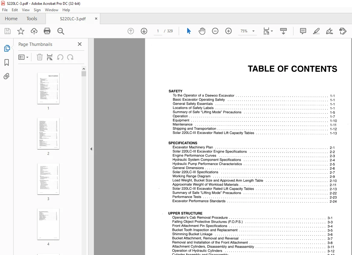
TABLE OF CONTENTS:
Daewoo Excavators Solar 220LC-III Serial Number 1001 and Up Shop Manual – PDF DOWNLOAD
SAFETY
To the Operator of a Daewoo Excavator 1-1
Basic Excavator Operating Safety 1-1
General Safety Essentials 1-1
Locations of Safety Labels 1-1
Summary of Safe “Lifting Mode” Precautions 1-5
Operation 1-7
Equipment 1-1 O
Maintenance 1-11
Shipping and Transportation 1-12
Solar 220LC-I II Excavator Rated Lift Capacity Tables 1-13
SPECIFICATIONS
Excavator Machinery Plan 2-1
Solar 220LC-III Excavator Engine Specifications 2-2
Engine Performance Curves 2-3
Hydraulic System Component Specifications 2-4
Hydraulic Pump Performance Characteristics 2-5
General Dimensions 2-6
Solar 220LC-I II Specifications 2-7
Working Range Diagram 2-9
Load Weight, Bucket Size and Approved Arm Length Table 2-10
Approximate Weight of Workload Materials 2-11
Solar 220LC-I II Excavator Rated Lift Capacity Tables 2-13
Summary of Safe “Lifting Mode” Precautions 2-22
Performance Tests 2-23
Excavator Performance Standards 2-24
UPPER STRUCTURE
Operator’s Cab Removal Procedure 3-1
Falling Object Protective Structures (FOPS) 3-3
Front Attachment Pin Specifications 3-4
Bucket Tooth Inspection and Replacement 3-5
Shimming Bucket Linkage 3-6
Bucket Attachment, Removal and Reversal 3-7
Removal and Installation of the Front Attachment 3-8
Attachment Cylinders, Disassembly and Reassembly 3-11
Operation of Hydraulic Cylinders 3-12
Cylinder Assembly and Disassembly 3-13
Cylinder Reassembly 3-17
Welding Precautions and Guidelines 3-19
Accumulator 3-20
Engine Components and Accessories 3-22
Counterweight Removal and Installation 3-23
Fuel Tank Removal and Installation 3-24
Engine Cooling System: Radiator/Oil Cooler 3-25
220LC-III Shop Manual SAFETY
Swing Bearing Maintenance 3-28
Center Joint (Swivel) Overhaul/Repair 3-29
Hydraulic System General Notes 3-33
Operation of Working Components 3-35
Main Pump Assembly Description 3-39
Pump Regulator Description 3-42
Hydraulic System General Precautions 3-47
Maintenance Service and Repair Procedure 3-48
Main Pump Parts List 3-49
Main Pump Disassembly and Reassembly 3-50
Reassembly of Main Pumps and Valve Block 3-53
Pump Regulator Parts List 3-56
Pump Regulator Disassembly and Reassembly 3-58
Swing Motor Basic Operation 3-62
Swing Motor Parts List 3-65
Rebuilding the Swing Motor – Disassembly 3-66
Swing Motor Reassembly 3-71
Swing Motor Final Drive (Gearbox) Parts List 3-77
Swing Motor Final Drive (Gearbox) Disassembly 3-79
Swing Motor Final Drive (Gearbox) Reassembly 3-83
Control Valve Operation 3-90
Control Valve Disassembly 3-100
Pump Flow Control Regulator 3-105
Electronic Proportional Control Valve 3-106
LOWER STRUCTURE
General Description 4-1
Travel Motor and Reduction Gearbox 4-2
Track Frame Gearbox Assembly 4-3
Travel Motor Assembly 4-4
Travel Motor Assembly Parts List 4-5
Travel Motor Operation 4-6
Travel Motor Final Drive (Gearbox) 4-9
Travel Motor and Gearbox Disassembly, Overhaul and Reassembly 4-12
Front Idler Roller 4-34
Lower Roller 4-37
Upper Roller 4-39
Track Spring and Track Adjusting Cylinder 4-42
Service Standards for Lower Travel Frame Components 4-43
Track Tensioning 4-45
ELECTRICAL SYSTEM
General Description 5-1
24 Volt Operation 5-2
Engine Start-up and Shutdown 5-3
Cylinder Preheat – Intake Air Electrical Heater 5-4
Alternator Circuit 5-5
Low Current Electrical Circuits 5-7
Climate Control (Air Conditioning) Circuit 5-9
Power Mode System Operating Components 5-11
Instrument Panel 5-12
Instrument Panel LED Displays and Input Terminal Connections 5-14
Instrument Panel Connector Arrangement 5-14
Instrument Panel Selector Switches 5-15
Instrument Panel Coolant Overheating Circuit 5-15
ii SAFETY 220LC-III Shop Manual
Instrument Panel Indicator Lights 5-15
Instrument Panel Engine Oil Pressure Circuit 5-16
Start-up Electrical Test Circuit 5-16
Interior Lighting 5-16
Hydraulic Pump Discharge Pressure Sensor 5-16
Power Mode Circuit Instrument Panel Summary 5-18
Power Mode System Basic Operation 5-19
Power Mode Ill 5-20
Power Mode 11 5-23
Power Mode I 5-24
Swing Priority Circuit 5-25
Swing and Arm Dump Combined Operation 5-26
Swing Priority and Arm Crowd Recovery Function 5-27
Loading Work Mode 5-28
Leveling Work Mode 5-29
Boom Up, Arm Crowd and Bucket Crowd Combined Operation 5-30
Lifting Mode: Boom Up and Arm Crowd Combined Operation 5-31
Forward Travel: Swing During Straight Travel 5-32
Forward Travel: Arm Operation or Boom Operation While Traveling 5-33
Bucket Operation While Traveling 5-34
ENGINE
Engine Specifications 6-1
Wear Limits/Specification, Major Engine Components 6-1
Engine Oil Pump Overhaul and Rebuilding 6-7
Fuel Injection Pump Installation, Alignment and Timing 6-9
Cylinder Headbolt Torque Requirements 6-11
Engine Throttle Controller 6-12
Engine Speed Sensor 6-14
INSPECTION, MAINTENANCE AND ADJUSTMENT
Periodic Inspection and Maintenance 7-1
Maintenance Intervals 7-2
Table of Recommended Lubricants 7-3
Inspection and Maintenance 7-4
Daily or Every 10 Operating Hours 7-4
Weekly or Every 50 Operating Hours 7-10
150 Operating Hou rs 7-11
Monthly or Every 250 Operating Hours 7-12
Three Months or Every 500 Operating Hours 7-14
Six Months or Every 1,000 Operating Hours 7-15
Annually or Every 2,000 Operating Hours 7-15
General Maintenance Procedures 7-17
Tightening Torque Specifications 7-19
Torque Wrench Extension Tools 7-20
Flange and Thread Sealant Assembly Compounds 7-22
Welding Precautions and Guidelines 7-24
Service Standards for Lower Travel Frame Components 7-25
Hydraulic System Cleanliness and Oil Leaks 7-29
Reference Notes for Foldout Wiring Harness Illustrations 7-30
TESTING, TROUBLESHOOTING AND ADJUSTING
Procedural Troubleshooting Baseline Recommendations 8-1
Pilot Pressure 8-2
Power Mode Valve : 8-3
Boom/Swing Priority 8-4
Negacon, Negative Control 8-5
Pressure Up Valve 8-6
Pump Input Power Control 8-7
Flow Meter and Flow Meter Kit Installation and Testing 8-9
Swing System Troubleshooting 8-10
Troubleshooting – Hydraulic Problems 8-12
Troubleshooting – Control Valve 8-20
Troubleshooting – Travel Control Valve 8-22
Troubleshooting – Joystick Control Valve 8-23
Troubleshooting – Engine Problems 8-24
Troubleshooting – Electrical System 8-28
EPOS-I11 Self-diagnostic Codes 8-29
Engine Throttle Controller 8-31
Service Points and Test Port Locations 8-33
Slow Return Valve 8-38
Customer Support: [email protected]
IMAGES PREVIEW OF THE MANUAL:
S.M 6/24