Trusted Business
Verified & Licensed
Virus Free Files
100% Safe Downloads
Secure Payment
SSL Protected
Instant Delivery
Available Immediately

Daewoo Excavator DX480LC DX520LC Shop Manual K1008703E – PDF
$32.95
Daewoo Excavator DX480LC DX520LC Shop Manual K1008703E – PDF DOWNLOAD
Instant PDF Download
Available immediately
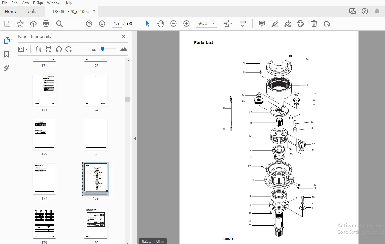
Save to Your Device
Download & keep forever
Antivirus Scanned
100% virus-free
Trusted Worldwide
175,000+ customers
Description
Daewoo Excavator DX480LC DX520LC Shop Manual K1008703E – PDF DOWNLOAD
FILE DETAILS:
Daewoo Excavator DX480LC DX520LC Shop Manual K1008703E – PDF DOWNLOAD
Language : English
Pages : 878
Downloadable : Yes
File Type : PDF
IMAGES PREVIEW OF THE MANUAL:

TABLE OF CONTENTS:
Daewoo Excavator DX480LC DX520LC Shop Manual K1008703E – PDF DOWNLOAD
000 K1008703E(DX480LC)TOC(2).pdf..............................................................  0
	000 K1008703E(DX480LC)TOC(2).pdf..........................................................  0
		Table of Contents.....................................................................  3
002 SP000142(46).pdf..........................................................................  0
	Safety Precautions........................................................................ 11
	Applicable Models......................................................................... 11
	To the Operator of a DOOSAN Daewoo Excavator.............................................. 12
		Learn the Signal Words Used with the Safety Alert Symbol.............................. 14
	General Safety Essentials................................................................. 16
		Accessory Applications................................................................ 16
		Lifting Capacity Rating Configuration................................................. 16
	Location of Safety Labels................................................................. 17
	Summary of Safety Precautions for Lifting in Digging Mode................................. 18
	Unauthorized Modifications................................................................ 19
	General Hazard Information................................................................ 19
		Safety Rules.......................................................................... 19
		Safety Features....................................................................... 19
		Inside Operator's Compartment......................................................... 20
		Clothing and Personal Protective Items................................................ 20
		Breathing Masks, Ear Protection May Be Required....................................... 21
		Vibration Level Information........................................................... 21
		Recommendations for Limiting Vibrations............................................... 21
		Mounting and Dismounting.............................................................. 22
		Fuel, Oil and Hydraulic Fluid Fire Hazards............................................ 23
		Precautions When Handling Fluids at High Temperature.................................. 23
		Asbestos Dust Hazard Prevention....................................................... 24
		Injury from Work Equipment............................................................ 24
		Fire Extinguisher and First Aid Kit................................................... 24
		Protection from Falling or Flying Objects............................................. 25
		Attachment Precautions................................................................ 26
		Accumulator........................................................................... 26
		Indoor Ventilation.................................................................... 26
		Emergency Exit........................................................................ 27
	Before Starting Engine.................................................................... 28
		Work Site Precautions................................................................. 28
		Checks Before Starting Engine......................................................... 29
		Engine Starting....................................................................... 29
		Before Operating Machine.............................................................. 30
	Machine Operation......................................................................... 32
		When Swinging or Changing Direction of Travel......................................... 32
		Travel Precautions.................................................................... 33
		Traveling on Slopes................................................................... 34
		Prohibited Operations................................................................. 34
		Precautions for Operation............................................................. 35
		Avoid High Voltage Cables............................................................. 36
		Protecting Cabin from Falling Object (Optional)....................................... 36
		Operate Carefully on Snow, Ice and in Very Cold Temperatures.......................... 37
		Operations on Slopes.................................................................. 37
		Parking Machine....................................................................... 38
		Never Let Anyone Ride on Attachment................................................... 38
	Maintenance............................................................................... 39
		Warning Tag........................................................................... 39
		Clean Before Inspection or Maintenance................................................ 39
		Proper Tools.......................................................................... 40
		Use of Lighting....................................................................... 40
		Fire Prevention and Explosion Prevention.............................................. 40
		Burn Prevention....................................................................... 41
		Welding Repairs....................................................................... 41
			Treatment for Electrical Welding to the Body Structure............................ 42
		Warning for Counterweight and Front Attachment Removal................................ 43
		Precautions for Removal, Installation, and Storage of Attachments..................... 43
		Precautions When Working on Machine................................................... 44
		Lock Inspection Covers................................................................ 44
		Crushing Prevention and Cutting Prevention............................................ 44
		Track Tension Adjustments Require Caution............................................. 45
		Supports and Blocking for Work Equipment.............................................. 45
		Action When Abnormality Is Found During Inspection.................................... 45
		Precautions with High-pressure Lines, Tubes and Hoses................................. 46
		Waste Materials....................................................................... 47
	Battery................................................................................... 48
		Battery Hazard Prevention............................................................. 48
		Boost Starting or Charging Engine Batteries........................................... 49
	Towing.................................................................................... 50
		Precautions When Towing............................................................... 50
	Shipping and Transportation............................................................... 51
		Obey State and Local Over-the-Road Regulations........................................ 51
	Lifting With Sling........................................................................ 51
003 s02Specifications(2).pdf..................................................................  0
	Specifications............................................................................ 53
004 SP000143(30).pdf..........................................................................  0
	Specification for DX480LC/ 520LC.......................................................... 55
		Safety Precautions.................................................................... 59
		Applicable Models..................................................................... 59
		General Description................................................................... 61
		Component Locations................................................................... 62
		General Dimensions (DX480LC).......................................................... 64
		General Dimensions (DX520LC).......................................................... 65
		Working Range (DX480LC)............................................................... 66
		Working Range (DX520LC)............................................................... 68
		General Specifications (DX480LC)...................................................... 70
		General Specifications (DX520LC)...................................................... 72
		Engine Performance Curves (Per DIN 6270 Standard)..................................... 74
		Approximate Weight of Workload Materials.............................................. 76
		Performance Tests..................................................................... 78
		Excavator Performance Standards....................................................... 79
			Test Conditions................................................................... 79
			Travel Speed and Travel Motor Balance (Steering Deviation) Tests.................. 79
				Speed Test.................................................................... 79
				Travel Deviation.............................................................. 81
			Swing Speed and Deceleration Force Test........................................... 81
				Swing Speed Test.............................................................. 81
				Swing Deceleration Force Test................................................. 82
			Cylinder Performance Tests........................................................ 83
				Boom Cylinders Test........................................................... 83
				Arm Cylinder Test............................................................. 83
				Bucket Cylinder Test.......................................................... 83
				Hydraulic Cylinder Natural Drop Test.......................................... 83
				Travel Motor Jack-up Test..................................................... 83
005 S03General Maintenance(2).pdf.............................................................  0
	General Maintenance....................................................................... 85
006 SP000016(20).pdf..........................................................................  0
	General Maintenance Procedures............................................................ 87
		Safety Precautions.................................................................... 91
		Applicable Models..................................................................... 91
		Welding Precautions and Guidelines.................................................... 92
		Hydraulic System - General Precautions................................................ 93
		Maintenance Service and Repair Procedure.............................................. 95
			General Precautions............................................................... 95
		Hydraulic System Cleanliness and Oil Leaks............................................ 96
			Maintenance Precautions for Hydraulic System Service.............................. 96
			Oil Leakage Precautions........................................................... 97
		Cleaning and Inspection............................................................... 98
			General Guidelines................................................................ 98
			Bearing inspection................................................................ 99
				Normal Bearing................................................................100
				Bent Cage.....................................................................100
				Galling.......................................................................101
				Abrasive Step Wear............................................................101
				Etching.......................................................................102
				Misalignment..................................................................102
				Indentations..................................................................102
				Fatigue Spalling..............................................................103
				Brinelling....................................................................103
				Cage Wear.....................................................................103
				Abrasive Roller Wear..........................................................104
				Cracked Inner Race............................................................104
				Smears........................................................................104
				Frettage......................................................................105
				Heat Discoloration............................................................105
				Stain Discoloration...........................................................105
007 SP000017(16).pdf..........................................................................  0
	Standard Torques..........................................................................107
		Safety Precautions....................................................................111
		Applicable Models.....................................................................111
		Torque Values for Standard Metric Fasteners...........................................112
		Torque Values for Standard U.S. Fasteners.............................................113
		Type 8 Phosphate Coated Hardware......................................................115
		Torque Values for Hose Clamps.........................................................116
		Torque Values for Split Flanges.......................................................117
		Torque Wrench Extension Tools.........................................................118
			Torque Multiplication.............................................................118
			Other Uses for Torque Wrench Extension Tools......................................119
			Tightening Torque Specifications (Metric).........................................119
				I. "Loctite" Fastener Adhesives...............................................121
				II. "Loctite" Pipe Thread Sealant.............................................121
				III. "Loctite" gasket/flange sealer...........................................121
				IV. "Loctite" retaining compounds.............................................122
				V. "Loctite" Adhesives........................................................122
008 S04Upper Structure(2).pdf.................................................................  0
	Upper Structure...........................................................................123
009 SP000018(10).pdf..........................................................................  0
	Cabin.....................................................................................125
		Safety Precautions....................................................................129
		Applicable Models.....................................................................129
		Removal...............................................................................130
		Installation..........................................................................132
010 SP000153(10).pdf..........................................................................  0
	Counterweight.............................................................................135
		Safety Precautions....................................................................139
		Applicable Models.....................................................................139
		General...............................................................................140
			Warning for Counterweight and Front Attachment Removal............................140
		Removal...............................................................................142
		Installation..........................................................................144
011 SP000155(16).pdf..........................................................................  0
	Fuel Tank.................................................................................145
		Safety Precautions....................................................................149
		Applicable Models.....................................................................149
		General Description...................................................................150
			Parts List........................................................................150
			Specifications....................................................................151
		Removal...............................................................................152
		Installation..........................................................................157
		Start-up Procedures...................................................................160
012 SP000158(10).pdf..........................................................................  0
	Swing Bearing.............................................................................161
		Safety Precautions....................................................................165
		Applicable Models.....................................................................165
		Swing Bearing Maintenance.............................................................166
			Operating Recommendation..........................................................166
			Measuring Swing Bearing Axial Play................................................166
			Measuring Bearing Lateral Play....................................................166
			Swing Bearing Basic Operation.....................................................167
			Rebuilding Swing Bearing..........................................................167
013 SP000160(46).pdf..........................................................................  0
	Swing Reduction Gear......................................................................171
		Safety Precautions....................................................................175
		Applicable Models.....................................................................175
		General Description...................................................................177
			Theory of Operation...............................................................177
			Parts List........................................................................178
			Specifications....................................................................179
		Troubleshooting, Testing and Adjustment...............................................180
		Removal...............................................................................181
		Disassembly...........................................................................182
		Cleaning and Inspection (Wear Limits and Tolerances)..................................189
		Reassembly............................................................................190
			Shaft and S/R Bearing Heatfit.....................................................190
			Assembly of Carrier Subassemblies.................................................190
				Cleaning Carrier..............................................................190
				Cleaning Planet Gear..........................................................190
				Assembly of No. 1 Carrier.....................................................190
				Assembly of No. 2 Carrier.....................................................193
			Assembly of Main Case.............................................................196
				Cleaning Casing and Other Parts...............................................196
				Assembly of Shaft and Pinion..................................................197
				Assembly of Seal and Bearing..................................................200
				Assembly of Ring Gear.........................................................205
				Assembly of Carrier...........................................................206
				Assembly of the Motor.........................................................210
		Installation..........................................................................216
		Startup Procedures....................................................................216
014 S05Lower Structure and Chassis(2).pdf.....................................................  0
	Lower Structure and Chassis...............................................................217
015 SP000171(40).pdf..........................................................................  0
	Track Assembly............................................................................219
		Safety Precautions....................................................................223
		Applicable Models.....................................................................223
		General Description...................................................................224
		Track Tension.........................................................................224
		Cleaning and Inspection (Wear Limits and Tolerances)..................................227
			Track Shoe........................................................................228
			Lower Roller......................................................................230
			Upper Roller......................................................................231
			Front Idler.......................................................................232
		Track Shoes and Links.................................................................233
			Track Removal.....................................................................233
			Track Installation................................................................234
		Front Idler Roller....................................................................236
			Parts List........................................................................236
			Front Idler Roller Disassembly....................................................237
			Front Idler Roller Reassembly.....................................................238
		Lower Roller..........................................................................240
			Parts List........................................................................240
			Lower Roller Removal..............................................................241
			Lower Roller Disassembly..........................................................241
			Lower Roller Reassembly...........................................................242
			Lower Roller Installation.........................................................243
		Upper Roller..........................................................................244
			Parts List........................................................................244
			Upper Roller Removal..............................................................245
			Upper Roller Disassembly..........................................................245
			Upper Roller Reassembly...........................................................248
		Track Spring and Track Adjusting Cylinder.............................................250
		Under Carrige Track Spring............................................................251
			Track Spring Assembly Diagram.....................................................251
			Track Spring Disassembly Diagram..................................................252
			Disassembly of the Track Spring Assembly..........................................253
			Assembly of the Track Spring......................................................255
016 SP000025(38).pdf..........................................................................  0
	Air Conditioner SP000025..................................................................259
		Safety Precautions....................................................................263
		Applicable Models.....................................................................263
		Air Conditioner System................................................................264
			Outline...........................................................................264
			Internal and External Filters.....................................................265
				How to check Indoor air filter................................................265
				How to check outdoor air filter...............................................265
			Air-Conditioning System Layout....................................................267
			Air Conditioner/Heater Circuit Diagram............................................268
			Air Conditioner/Heater Unit.......................................................269
				Air Flow Diagram..............................................................269
				Door Open by Vent Modes.......................................................270
				Main Components...............................................................270
				Actuator - Internal/external air exchange.....................................272
				Air Flow Control Module.......................................................272
			Relay - Blower....................................................................273
			Relay - A/C.......................................................................273
			Duct Sensor.......................................................................273
			Water Temp Sensor.................................................................274
			Internal Air Temp Sensor..........................................................274
			Ambient Air Temperature Sensor....................................................274
			Sun Sensor........................................................................275
			Control Panel.....................................................................275
				Appearance and Terminal Arrangement...........................................275
				Terminal Terms................................................................276
				Control Logic.................................................................276
				Self Diagnosis................................................................281
				Ambient Temp Display..........................................................282
			Compressor........................................................................283
			Receiver Dryer....................................................................283
		Troubleshooting.......................................................................284
			Refrigerant Pressure Check........................................................284
		Weight of R134a Gas Used In Machines..................................................287
		Refrigerant System Repairs............................................................288
			Refrigerant Safe Handling Procedures..............................................288
			Repair and Replacement Procedure..................................................289
			Refrigerant Recovery..............................................................291
			Vacuuming Refrigerant System......................................................291
			Leakage Check.....................................................................292
			Refrigerant Charging..............................................................293
			Inspecting System For Leakage.....................................................295
017 S06Engine and Drive Train(2).pdf..........................................................  0
	Engine and Drive Train....................................................................297
018 SP000026(8).pdf...........................................................................  0
	Drive Coupling (Main Pump)................................................................299
		Safety Precautions....................................................................303
		Applicable Models.....................................................................303
		Drive Coupling........................................................................304
		Installation of Drive Coupling........................................................305
			Installation Procedure............................................................305
019 S07Hydraulics(2).pdf......................................................................  0
	Hydraulics................................................................................307
020 SP000179(38).pdf..........................................................................  0
	Hydraulic System Troubleshooting, Testing and Adjustment..................................309
		Safety Precautions....................................................................313
		Applicable Models.....................................................................313
		Hydraulic System - General Notes......................................................314
		Hydraulic Schematic...................................................................316
			General Notes.....................................................................316
		Operation of Working Components.......................................................318
			Boom Operating Circuit............................................................318
			Boom Up Circuit...................................................................318
			Boom Down Circuit.................................................................319
			Arm Operating Circuit.............................................................319
			Arm Crowd Circuit.................................................................320
			Arm Dump Circuit..................................................................320
			Bucket Operating Circuit..........................................................321
			Bucket Crowd Circuit..............................................................321
			Bucket Dump Circuit...............................................................321
			Swing Operating Circuit...........................................................321
			Right Swing Operating Circuit.....................................................322
			Left Swing Operating Circuit......................................................322
			Swing Relief Valve and Makeup Valve...............................................322
			Travel Operating Circuit..........................................................322
			Forward Travel Circuit............................................................323
			Reverse Travel Circuit............................................................323
		Procedural Troubleshooting Baseline Recommendations...................................324
			Initial Checks and Tests to Establish Operating Condition of the Excavator........324
				Triage Summary................................................................324
		Pilot Pressure........................................................................326
			Adjustment and Testing............................................................326
		Power Mode Valve......................................................................327
			Current Signal and Hydraulic Pressure Adjustments.................................327
		Boom/Front Priority Valve.............................................................329
			Control Valve Pressure and Current Adjustments....................................329
		Pressure Up Valve.....................................................................330
			Checks and Adjustments............................................................330
		Pump Input Power Control..............................................................332
			Pump Regulator Adjustment.........................................................332
		Flow Meter and Flow Meter Kit Installation and Testing................................335
			Installation and Testing Procedure................................................335
		Swing System Troubleshooting..........................................................337
			Precautions/Initial Checks........................................................337
			Swing Relief Valve Checking and Adjustment........................................337
		Troubleshooting - Swing Gearbox.......................................................340
		Troubleshooting - Hydraulic Problems..................................................341
		Troubleshooting - Control Valve.......................................................342
		Troubleshooting - Travel Control Valve................................................344
		Troubleshooting - Joystick Control Valve..............................................344
021 SP000028(8).pdf...........................................................................  0
	Accumulator...............................................................................347
		Safety Precautions....................................................................351
		Applicable Models.....................................................................351
		General Description...................................................................352
			Specifications....................................................................354
022 SP000181(14).pdf..........................................................................  0
	Center Joint (Swivel).....................................................................355
		Safety Precautions....................................................................359
		Applicable Models.....................................................................359
		General Description...................................................................360
			Center Joint Disassembly Diagram..................................................361
		Disassembly...........................................................................362
		Reassembly............................................................................365
023 SP000193(16).pdf..........................................................................  0
	Cylinders.................................................................................369
		Safety Precautions....................................................................373
		Applicable Models.....................................................................373
		Structure of Cylinder.................................................................374
			Structure of Arm Cylinder.........................................................374
			Structure of Boom Cylinder........................................................376
			Structure of Bucket Cylinder......................................................378
			Disassembly of Cylinder...........................................................379
			Reassembly of Cylinder............................................................383
024 SP000194(34)주의.pdf........................................................................  0
	Swing Motor...............................................................................385
		Safety Precautions....................................................................389
		Applicable Models.....................................................................389
		Operation Manual......................................................................390
			Information on Marking............................................................390
			Specifications....................................................................391
			Structure and Operational Principles..............................................392
				Structure.....................................................................392
				Operational Principles........................................................394
				Brake Subassembly.............................................................398
			Cautions..........................................................................399
				Check Points..................................................................399
				Rotation Direction............................................................399
				External Load on Shaft End....................................................400
				Active Oil and Temperature Range..............................................400
				Filter........................................................................401
				Installation and Piping.......................................................402
				Fillup and Air Discharge......................................................402
				Cautions During Start.........................................................402
				Causes and Solutions of Problems..............................................402
				General Cautions..............................................................402
				How to Check Defects of Motor.................................................403
				Symptoms and Solutions of Problems............................................404
		Maintenance Instructions..............................................................406
			Disassembly and Assembly..........................................................406
				Bolt Tightening Torque........................................................406
				Tools Used for Disassembly and Assembly.......................................406
				Disassembly...................................................................408
				Assembly......................................................................412
			Maintenance.......................................................................418
				References for Replacement of Worn Parts......................................418
				Fixing References for Sliding Parts...........................................418
025 SP000185(64).pdf..........................................................................  0
	Travel Motor (With Gearbox) (A6V160HD) SP000185...........................................419
		Safety Precautions....................................................................423
		Applicable Models.....................................................................423
		General Description...................................................................424
			Theory Of Operation...............................................................424
			Hydraulic Motor Operation.........................................................425
				1. Hydraulic Motor operation..................................................425
				2. Brake Valve................................................................426
				3. Parking Brake..............................................................428
				4. High and Low Speed Switching Device........................................430
			Reduction Gearbox Operation.......................................................432
			Parts List........................................................................434
				Travel Motor..................................................................434
				Travel Motor - Rotary Group...................................................436
				Travel Motor - Control........................................................438
				Travel Motor Speed Reduction Gearbox Assembly.................................440
			Specifications....................................................................442
			Tightening Torques................................................................443
		Travel Motor Disassembly..............................................................445
			Sectional View....................................................................445
			Seal Kits and Component Groups....................................................446
			Sealing Drive Shaft...............................................................449
			Sealing Control Parts.............................................................450
			Sealing Relief Valve..............................................................450
			Disassembly Port Plate............................................................451
			Exchanging Rotary Group...........................................................456
		Travel Motor Speed Reduction Gearbox Disassembly......................................459
		Cleaning and Inspection (Wear Limits and Tolerances)..................................468
		Travel Motor Speed Reduction Gearbox Reassembly.......................................469
		Travel Motor Reassembly...............................................................479
			Rotary Group Assembly.............................................................479
			Rotary Group Adjustment (See Serve Information)...................................480
			Assembly of Port Plate............................................................482
026 SP000186(56).pdf..........................................................................  0
	Main Pump (Rexroth).......................................................................483
		Safety Precautions....................................................................487
		Applicable Models.....................................................................487
		ectional View.........................................................................488
			A8VO200LA1KH1/63..................................................................488
		General Repair Guidelines.............................................................490
		Seal Kits and Sub- assemblies.........................................................492
		Sealing the Drive Shaft...............................................................496
		Gear Pump Sealing.....................................................................498
		Remove the Control Housing............................................................500
		Control Module........................................................................504
			Control Module LR.................................................................504
			Control Module H..................................................................505
		Removing the Controller...............................................................506
		Valve Plate With Valves...............................................................508
		Remove the Rotary Groups..............................................................509
		Remove the Intermediate Wheel.........................................................512
		Remove Auxiliary Drive................................................................514
		Inspection............................................................................517
		Re-fitting the Rotary Group...........................................................522
		Pump Assembly.........................................................................524
			Assembly Guideline................................................................525
			Adjustment of the Hydraulic Component of the Rotary Group.........................526
		Hydraulic Component - Measurement "D".................................................526
			Measuring Device - Hydraulic Component 452 269....................................526
			Mounting Position.................................................................527
			Measuring Procedure...............................................................528
		Installation of Control Housing.......................................................530
		Assembly of Intermediate Wheel........................................................533
		Installation of Gear Pump.............................................................534
		Installation of Cover / Auxiliary Drive...............................................535
		Assembly Guidelines for Tightening Torques............................................536
			Bolts (To N 08.001)...............................................................536
			Plugs with Internal Hexagon and Profile Seal Ring (to N 02.009)...................536
			Seal-lock - Sealing Nuts (to N 02.100)............................................537
027 SP000187(58).pdf..........................................................................  0
	Control Valve (Kayaba Model KVMG-400-DA)..................................................539
		Safety Precautions....................................................................543
		Applicable Models.....................................................................543
		General Description...................................................................544
			When All Spools are in Neutral....................................................544
				Neutral Passage (Figure 1 and Figure 2).......................................544
				Signal Passage (Figure 2).....................................................546
			Single Operation..................................................................548
				Travel Spool Shifting (Figure 3 and Figure 4).................................548
				Swing Spool Shifting (Figure 4)...............................................550
				Boom Spool Shifting...........................................................551
				Spare Spool Shifting (Figure 8)...............................................554
				Bucket Spool Shifting (Figure 8)..............................................554
				Arm Spool Shifting............................................................555
				Neutral-cut Spool Shifting (Figure 11)........................................558
				Parallel Throttle for Arm (Figure 11).........................................558
				Relief Valve..................................................................559
			Combined Operation................................................................560
				Travel Combined Operation (Figure 13).........................................560
				Swing Combined Operation (Figure 14)..........................................562
			Anti Drift Valve..................................................................563
			Main Relief Valve.................................................................563
			Overload Relief Valve.............................................................564
			Low Pressure Relief Valve.........................................................566
			Parts List........................................................................567
				Spool Assembly (4, Bucket)....................................................571
				Spool Assembly (5, Boom)......................................................571
				Spool Assembly (6, Travel)....................................................571
				Spool Assembly (7, Straight Travel)...........................................572
				Spool Assembly (8, Arm1)......................................................572
				Spool Assembly (9, Service)...................................................572
				Spool Assembly (10, Boom 2)...................................................573
				Spool Assembly (11, Swing)....................................................573
				Spool Assembly (3, Arm 2).....................................................573
				Spool Assembly (20, Arm Regeneration Release Valve............................573
				Spool Assembly (24)...........................................................574
				Poppet Assembly (36)..........................................................574
				Plug Assembly (51)............................................................574
				Plug Assembly (58)............................................................574
				Relief Valve Assembly (48)....................................................575
				Relief Valve Assembly (49)....................................................575
				Relief Valve Assembly (50)....................................................576
			Specifications....................................................................576
		Troubleshooting, Testing and Adjustment...............................................577
			General...........................................................................577
			Relief Valve......................................................................578
			Hydraulic System..................................................................578
			Adjustment of Relief Valve........................................................578
				Main Relief Valve.............................................................578
				Over Load Relief Valve........................................................579
		Disassembly...........................................................................580
			General Instructions for Disassembly..............................................580
			Disassembly of Main Spool (3) - (11)..............................................580
			Disassembly of Subspool (24)......................................................581
			Disassembly of Subspool (20)......................................................581
			Disassembly of Anti Drift Valve of Boom and Arm...................................582
			Disassembly of Swing Load Check...................................................582
			Disassembly of Load Check.........................................................583
			Disassembly of Other Check Valves.................................................583
			Disassembly Of Flange.............................................................583
			Disassembly of Relief Valve.......................................................584
			Disassembly of Other Flange.......................................................584
			Disassembly of Main Relief Valve..................................................585
			Disassembly of Overload Relief Valve..............................................586
			Disassembly of Low Pressure Relief Valve..........................................586
		Cleaning and Inspection (Wear Limits and Tolerances)..................................587
			Cleaning..........................................................................587
			Inspection........................................................................587
		Reassembly............................................................................588
			Subassembly.......................................................................588
				Main Spool (3) - (11).........................................................588
				Subspool (20).................................................................588
				Subspool (24).................................................................589
				Boom, Arm Anti Drift Valve....................................................589
				Swing Load Check..............................................................589
			Reassembly of Control Valve.......................................................589
				Reassembly of Load Check Valve................................................589
				Reassembly of Swing Load Check................................................590
				Reassembly of Other Check Valve...............................................590
				Reassembly of Flange..........................................................591
				Reassembly of Boom and Arm Anti Drift Valve...................................591
				Reassembly of Relief Valve....................................................591
				Reassembly of Subspool (24)...................................................591
				Reassembly of Subspool (20)...................................................592
				Reassembly of Main Spool (3) - (11)...........................................592
				Reassembly of Other Plugs.....................................................592
				Reassembly of Main Relief Valve...............................................593
				Reassembly of Overload Relief Valve...........................................594
				Reassembly of Low Pressure Relief Valve.......................................594
		Installation..........................................................................595
		Start-up Procedures...................................................................595
028 SP000189(22).pdf..........................................................................  0
	Remote Control Valve (Work Lever / Joystick)..............................................597
		Safety Precautions....................................................................601
		Applicable Models.....................................................................601
		General Description...................................................................603
			Structure.........................................................................603
			Function..........................................................................603
			Parts List........................................................................604
			Specifications....................................................................606
				Performance...................................................................606
		Torques...............................................................................606
		Tools and Materials...................................................................606
		Disassembly...........................................................................607
		Cleaning and Inspection (Wear Limits and Tolerances)..................................611
		Reassembly............................................................................611
		Start-up Procedures...................................................................617
029 SP000070(26).pdf..........................................................................  0
	Travel Control Valve (With Damper) SP000070...............................................619
		Safety Precautions....................................................................623
		Applicable Models.....................................................................623
		General Description...................................................................624
			Theory of Operation...............................................................624
			Deceleration Valve................................................................625
			Dampening Parts of the Control Section............................................626
		Causes of Faults and Measures.........................................................629
			Parts List........................................................................630
			Specifications....................................................................631
			Torques...........................................................................631
		Removal...............................................................................632
		Disassembly...........................................................................633
		Cleaning and Inspection (Wear Limits and Tolerances)..................................636
		Assembly..............................................................................637
		Installation..........................................................................643
		Startup Procedures....................................................................644
030 SP000191(14).pdf..........................................................................  0
	Solenoid Valve Assembly...................................................................645
		Safety Precautions....................................................................649
		Applicable Models.....................................................................649
		Parts List............................................................................650
		Functions of 5-Solenoid Valve Assembly Package........................................651
			Functions of Solenoid Valve Assembly Package......................................651
				This solenoid valve assembly package have the following functions.............651
				Functions and Operations of Solenoid Valves...................................651
				Detailed Functions and Operations of Solenoid Valves..........................651
			Assembly Diagram and Tools Required...............................................653
				Cautions During Disassembly and Reassembly....................................654
			Solenoid Valve Diagram............................................................655
			Check Points and Solutions for Problems...........................................656
				Checking of Pilot Pressure for Defects........................................657
031 SP000192(12).pdf..........................................................................  0
	Breaker EPPR Valve (Opt)..................................................................659
		Safety Precautions....................................................................663
		Applicable Models.....................................................................663
		Structure.............................................................................664
			Numbers and Names of Parts........................................................664
		Functions and Operation...............................................................665
		Cautions for Operation................................................................665
		Maintenance Instructions..............................................................666
			Maintenance.......................................................................666
				Bolt Tightening Torque........................................................666
				Tools Used for Disassembly and Assembly.......................................666
			Disassembly.......................................................................667
			Assembly..........................................................................668
032 SP000209(22).pdf..........................................................................  0
	Fan Motor (Vane Type).....................................................................671
		Safety Precautions....................................................................675
		Applicable Models.....................................................................675
		Parts list............................................................................676
		Introduction and Description..........................................................677
			General...........................................................................677
			Description.......................................................................677
			Applications......................................................................677
			Operation.........................................................................678
		Operating Characteristics - Typical...................................................679
			Performance Data..................................................................679
			Loads on Shaft....................................................................680
				Loads on Shaft................................................................680
				Lifetime Under Load...........................................................680
		Mounting Flange and Coupling..........................................................681
			Mounting Flange...................................................................681
			Misalignment......................................................................681
			Loads on Shaft....................................................................681
			Splined Shafts....................................................................681
			Shafts............................................................................682
			Taper Shafts......................................................................682
		Pipe Connection.......................................................................682
			Pipe..............................................................................682
			Flange Connections................................................................683
			External Drain....................................................................683
		Cleanliness and Seals.................................................................684
			Fluid Cleanliness.................................................................684
			Seals S1 : Nbr (Nitrile Base Polymere)............................................684
			Seals S4 : Epr (Ethylene Propylene Polymere)......................................684
			Seals S5 : Fpm (Fluorocarbon).....................................................684
		Maintenance...........................................................................685
			General...........................................................................685
			Disassembly.......................................................................685
			Reassembly........................................................................687
			Priming...........................................................................689
			Cold Starting.....................................................................689
			Changing Porting Position.........................................................689
			Cartridge Replacement.............................................................690
			End Cap Replacement...............................................................690
			Shaft Replacement.................................................................690
			Shaft Seal Replacement............................................................690
			Seal Driver.......................................................................691
		Couping Dimensions....................................................................691
			Taper Keyed Shafts................................................................691
033 SP000208(18).pdf..........................................................................  0
	Gear Pump (Fan Cooling Drive).............................................................693
		Safety Precautions....................................................................697
		Applicable Models.....................................................................697
		Disassembling Single Gear Pump........................................................698
		Reassembling Single Gear Pump.........................................................701
		Disassembling Double Gear Pump(Opt)...................................................704
		Reassembling Double Gear Pump(Opt)....................................................707
034 SP000207(6).pdf...........................................................................  0
	Fan Cooling Flow In-Out Change Valve......................................................711
		Safety Precautions....................................................................715
		Applicable Models.....................................................................715
		Cooling Fan a Change of Direction Valve...............................................716
035 SP000212(10).pdf..........................................................................  0
	Hydraulic Schematic DX480LC/ 520LC........................................................717
		Safety Precautions....................................................................721
		Applicable Models.....................................................................721
		General Description...................................................................723
		DX480LC / DX520LC.....................................................................724
036 S08Electrical System(2).pdf...............................................................  0
	Electrical System.........................................................................727
037 SP000197(116).pdf.........................................................................  0
	Electrical System SP000197................................................................729
		Safety Precautions....................................................................735
		Applicable Models.....................................................................735
		Introduction..........................................................................737
			Electric Wire Color...............................................................737
		Electrical Supply System..............................................................738
		Engine Starting Circuit...............................................................740
			Start Operation...................................................................740
			After Start.......................................................................742
				Operation of the Start Circuit (2) Immediately After Start....................743
		Engine Preheating System..............................................................744
		Engine Stop...........................................................................746
		Charging System.......................................................................748
		Monitoring System.....................................................................749
			Instrument Panel..................................................................750
			Monitoring System Schematic.......................................................752
		Operation.............................................................................754
			Instruments.......................................................................754
		Warning and Indicator Lights..........................................................756
			Indication of Warning Lights......................................................756
			Indication of Multifunction Gauge and Letter Information Area.....................757
		Initial Operation.....................................................................759
		Mode Selector Switch..................................................................759
			Power Mode / Trenching Mode Switch................................................759
			Auto Idle Switch..................................................................759
		Graphic Information Area Display......................................................760
			Overview..........................................................................760
			Main Menus for the Graphic Display Area...........................................761
			Menu Selector Buttons.............................................................761
			Menu Selector Buttons.............................................................761
		Main Menu.............................................................................762
			Language..........................................................................762
			Set Clock.........................................................................763
			Filter/Oil Info...................................................................763
				Menu Display Order and Icon Explanation.......................................764
			Adjust Display....................................................................764
			Set Password......................................................................765
		Special Menu..........................................................................766
			Entering/Accessing and Exiting/Escaping Menus.....................................766
				Entering/Accessing Menus......................................................766
				Exiting/Escaping Menus........................................................767
			Special Menu Selections...........................................................767
				Information of Machine Status.................................................767
				Failure Information...........................................................771
				Information of Machine Operation..............................................779
				Machine Operation Info Screen.................................................782
		Electronic Hydraulic Control System (eEPOS)...........................................784
			Control System Schematic..........................................................784
		Power Mode Control....................................................................786
			Operation.........................................................................788
				1. Power Mode.................................................................788
				2. Standard Mode..............................................................790
				3) Operation in case of failure in the control system (Aux mode operation)....790
		Power Mode Control Circuit Diagram....................................................792
		Work Mode Control.....................................................................794
			Operation.........................................................................795
				1. Digging Mode...............................................................795
				2. Trenching Mode.............................................................795
		Work Mode Control Circuit Diagram.....................................................796
		Engine Control System.................................................................797
		Engine Control Dial...................................................................798
		Engine Control Circuit Diagram........................................................800
		Automatic Deceleration Control (Auto Idle Control)....................................802
		Engine Overheat Protection System.....................................................804
		Power Boost Mode......................................................................806
			Operation.........................................................................806
			Power Boost Control Circuit Diagram...............................................808
		Automatic Travel Speed Control........................................................810
			Automatic Travel Speed Control Circuit Diagram....................................812
		Selfdiagnostic Function...............................................................813
			eEPOS Controller..................................................................813
		Air Conditioner System................................................................815
			Outline...........................................................................815
			Internal and External Filters.....................................................816
				How to check Indoor air filter................................................816
				How to check outdoor air filter...............................................816
			Air-Conditioning System Layout....................................................818
			Air Conditioner/Heater Circuit Diagram............................................819
			Air Conditioner/Heater Unit.......................................................820
				Air Flow Diagram..............................................................820
				Door Open by Vent Modes.......................................................821
				Main Components...............................................................821
				Actuator - Internal/external air exchange.....................................823
				Air Flow Control Module.......................................................823
			Relay - Blower....................................................................824
			Relay - A/C.......................................................................824
			Duct Sensor.......................................................................824
			Water Temp Sensor.................................................................825
			Internal Air Temp Sensor..........................................................825
			Ambient Air Temperature Sensor....................................................825
			Sun Sensor........................................................................826
			Control Panel.....................................................................826
				Appearance and Terminal Arrangement...........................................826
				Terminal Terms................................................................827
				Control Logic.................................................................827
				Self Diagnosis................................................................831
				Ambient Temp Display..........................................................832
			Compressor........................................................................833
			Receiver Dryer....................................................................833
		Control of Cooling Fan................................................................834
			Control of Cooling Fan Speed......................................................834
			Control of Reverse Rotation of Cooling Fan........................................834
			Cooling Fan Control Circuit.......................................................835
		Wiper System..........................................................................836
			Wiper Circuit.....................................................................836
			Wiper operation...................................................................837
				Continuous operation..........................................................837
				Intermittent operation........................................................837
		Lighting System.......................................................................840
			Lighting System Circuit Diagram...................................................840
			Kind of Light.....................................................................841
			Operation.........................................................................841
		Audio Controller......................................................................842
			Audio Controller Circuit Diagram..................................................842
				Operations Via Audio Control Panel............................................843
038 SP000213(10).pdf..........................................................................  0
	Electrical Schematic DX480LC/ 520LC.......................................................845
		Safety Precautions....................................................................849
		Applicable Models.....................................................................849
		General Description...................................................................851
		DX480LC/ 520LC........................................................................852
039 S09Attachments(2).pdf.....................................................................  0
	Attachments...............................................................................855
040 SP000205(12).pdf..........................................................................  0
	Boom and Arm..............................................................................857
		Safety Precautions....................................................................861
		Applicable Models.....................................................................861
		Front Attachment Pin Specifications...................................................862
		Front Attachment - Removal and Installation...........................................863
			Arm Removal Procedure.............................................................863
			Boom Removal Procedure............................................................866
		Installation..........................................................................867
			Arm Installation Procedure........................................................867
			Boom Installation Procedure.......................................................867
		Start-up Procedures...................................................................868
041 SP000206(10).pdf..........................................................................  0
	Bucket....................................................................................869
		Safety Precautions....................................................................873
		Applicable Models.....................................................................873
		Bucket Tooth Inspection and Replacement...............................................874
		Bucket O-ring Replacement.............................................................875
		Bucket Attachment, Removal and Reversal...............................................877
			Detaching the Bucket..............................................................877
			Attaching the Bucket..............................................................877
S.S 06/24