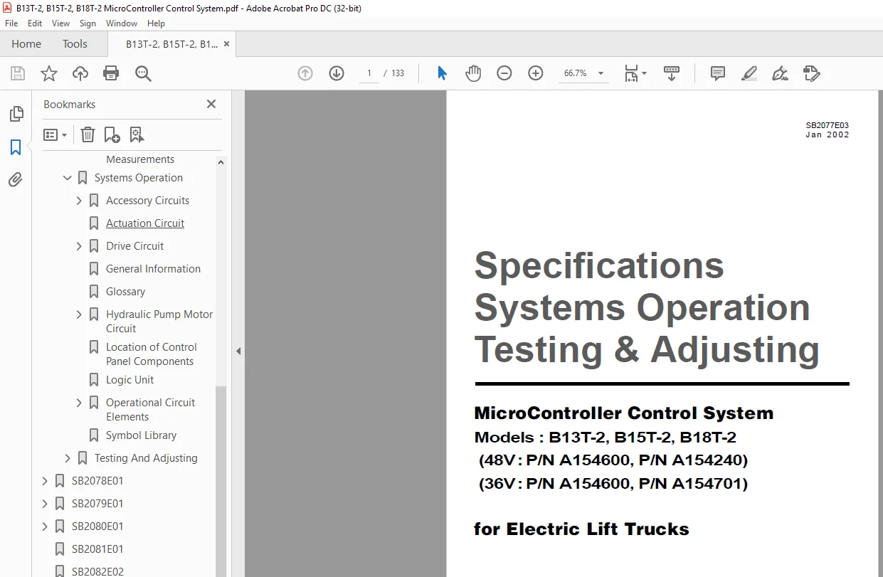
Daewoo Doosan MicroController Control System B13T-2 to B18T-2 Testing Adjusting Manual SB2077E03
$25.95
Daewoo Doosan MicroController Control System B13T-2 to B18T-2 Testing Adjusting Manual SB2077E03 – PDF DOWNLOAD
Description
Daewoo Doosan MicroController Control System B13T-2 to B18T-2 Testing Adjusting Manual SB2077E03 – PDF DOWNLOAD
FILE DETAILS:
Daewoo Doosan MicroController Control System B13T-2 to B18T-2 Testing Adjusting Manual SB2077E03 – PDF DOWNLOAD
Language :English
Pages :133
Downloadable : Yes
File Type : PDF
IMAGES PREVIEW OF THE MANUAL:
DESCRIPTION:
Daewoo Doosan MicroController Control System B13T-2 to B18T-2 Testing Adjusting Manual SB2077E03 – PDF DOWNLOAD
Important Safety Information
Most accidents involving product operation, maintenance and repair are caused by failure to observe basic safety
rules or precautions. An accident can often be avoided by recognizing potentially hazardous situations before an
accident occurs. A person must be alert to potential hazards. This person should also have the necessary
training, skill and tools to perform these functions properly.
Improper operation, Iubrication, maintenance or repair of this product can be dangerous and could result
in injury or death.
Do not operater or perform any lubrication, maintenance or repair on this product, until you have read
and understood the operation, lubrication, maintenance and repair information.
Safety precautions and warnings are provided in this manual and on the product. If these hazard warnings are
not heeded, bodily injury or death could occur to you or other persons.
The hazards are identified by the “Safety Alert Symbol” and followed by a “Signal Word” such as “WARNING” as
shown below.
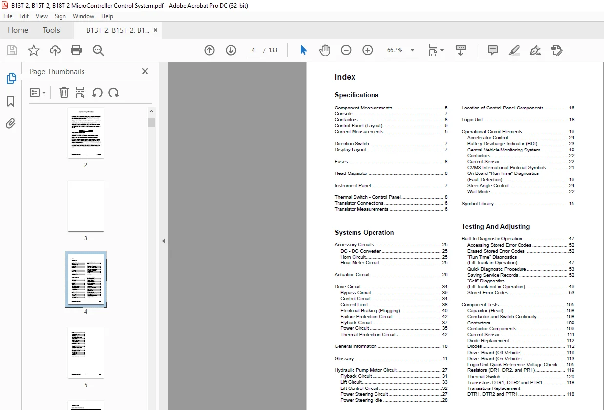
TABLE OF CONTENTS:
Daewoo Doosan MicroController Control System B13T-2 to B18T-2 Testing Adjusting Manual SB2077E03 – PDF DOWNLOAD
Contents:
Specifications
Systems Operation
Testing And Adjusting
SB2076E01 0
SB2003E00 0
SB2004E00 0
SB2077E03 0
Index 3
Specifications 5
Component Measurements 5
Console 7
Contactors 8
Control Panel (Layout) 9
Current Measurements 5
Direction Switch 7
Display Layout 7
Fuses 8
Head Capacitor 8
Instrument Panel 7
Thermal Switch – Control Panel 8
Transistor Connections 6
Transistor Measurements 6
Systems Operation 11
Accessory Circuits 25
DC-DC Converter 25
Horn Circuit 25
Hour Meter Circuit 25
Actuation Circuit 26
Drive Circuit 34
Bypass Circuit 39
Control Circuit 34
Current Limit 38
Electrical Braking (Plugging) 40
Failure Protection Circuit 42
Flyback Circuit 37
Power Circuit 35
Thermal Protection Circuits 42
General Information 18
Glossary 11
Hydraulic Pump Motor Circuit 27
Flyback Circuit 31
Lift Circuit 33
Lift Control Circuit 32
Power Steering Circuit 27
Power Steering Idle 28
Location of Control Panel Components 16
Logic Unit 18
Operational Circuit Elements 19
Accelerator Control 24
Battery Discharge Indicator (BDI) 23
Central Vehicle Monitoring System 19
Contactors 22
Current Sensor 22
CVMS International Pictorial Symbols 21
On Board “Run Time” Diagnostics 19
Steer Angle Control 24
Wait Mode 22
Symbol Library 15
Testing And Adjusting 43
Built-In Diagnostic Operation 47
Accessing Stored Error Codes 52
Erased Stored Error Codes 52
“Run Time” Diagnostics (Lift Truck in Operation) 47
Quick Diagnostic Procedure 53
Saving Service Records 52
“Self” Diagnostics (Lift Truck not in Operation) 49
Stored Error Codes 53
Component Tests105
Capacitor (Head) 108
Conductor and Switch Continuity 108
Contactors 109
Contactor Components 109
Current Sensor 111
Diode Replacement 112
Diodes 112
Driver Board (Off Vehicle)116
Driver Board (On Vehicle)113
Logic Unit Quick Reference Voltage check105
Resistors (DR1, DR2 and PR1)119
Thermal Switch 120
Transistors DTR1,DTR2 and PTR1118
Transistor Replacement DTR1, DTR2 and PTR1118
Control and Power System Operational Checks 46
Electrical System Adjustments121
Accelerator Control Linkage121
BDI Adjustment124
Bypass Dropout Adjustment – Stall Protection128
Current Limit Test and Adjustment127
Electrical Braking (Plugging) Current Test and Adjustment 128
Lift Sensor122
Parking Brake Switch121
Rapid Tune-Up Procedure124
Tilt and Auxiliary Switches123
Valve Control Card Adjustment122
Preparation Tests and Check 43
Programmable Features129
Activating Default Settings129
Programmable or Settable Option Features130
Quick Procedure for Programmable Features 132
Setting Procedure Option Features129
System Tests and Adjustments102
Discharging Head Capacitor 102
Logics Removal103
“Run Time” Tests103
Test Equipment102
Troubleshooting 43
Troubleshooting Problem List 54
SB2078E01 0
Index 4
Specifications 6
Brake 12
Drive Motor 8
Final Drive 9
General Tightening Torques 6
Motor and Transmission 11
Wheel Mounting 10
Systems Operation 13
Drive Motor 14
Final Drive 15
General Information 13
Testing And Adjusting 16
Brake 29
Connecting the brake cable 29
Connecting the hydraulic brake system 29
Replenishing With Transmission Fluid 30
Drive Motor 21
Armature Terminal Test 26
Armature Tests 22
Brush Holder Test 26
Brush Life Estimate 27
Commutator Inspection 24
Field Coil and Terminal Tests 25
Motor Brushes 21
Thermal Switch Tests 27
Motor and Transmission 28
Motor Transmission Unit and Vehicle Frame 29
Troubleshooting 16
Checks During Operation 16
Drive Motor 16
Transmission 20
Visual Checks 16
Disassemble and Assembly 31
Drive Axle 31
SB2079E01 0
Index 3
Specifications 5
Dual Steer Axle And Wheel 12
Hydraulic Control Valve 5
Hydraulic Pump 6
Hydraulic Pump Motor 13
Lift Cylinders 7
Standard 7
Full Free Triple Lift and Full Free Lift Primary 7
Full Free Lift Secondary 8
Full Free Triple Lift Secondary 8
Priority Valve 10
Sideshift Cylinder 6
Steer Axle And Wheel 12
Steering Gear 11
Steering Wheel 10
Tilt Cylinder 9
Systems Operation 14
Brake System 27
Master Cylinder 27
Electric Motors 28
Hydraulic Pump Motor 28
Hydraulic System 14
Control Valve 16
Steering System 23
Steering Unit 24
Testing & Adjusting 30
Brake System 44
Brake System Air Removal 44
Parking Brake Control Group Adjustment 46
Parking Brake Test 45
Pedal Adjustment 45
Hydraulic Pump Motor 46
Armature Tests 48
Brush Holder Test 51
Brush Life Estimate 52
Commutator Inspection 49
Field Coil And Terminal Tests 50
Motor Brushes 46
Thermal Switch(Thermostat) Tests 51
Hydraulic System 40
Lift Cylinders Air Removal 41
Relief Valve Pressure Check 40
Steering System 42
Steer Wheel Bearing Adjustment 42
Steering System Air Removal 42
Steering System Pressure Check 43
Troubleshooting 30
Brake System 35
Electric Motors 36
Hydraulic System and Mast 30
Steering System 34
Visual Checks 30
SB2080E01 0
Index 3
Accelerator Control Switch 17
Brake Master Cylinder 38
Control Panel 49
Counterwieght 54
Drive Motor & Drive Axle 51
Hood(with seat) Assembly 5
Hydraulic Control Valve 7
Hydraulic Pump 14
Hydraulic Pump Motor 13
Overhead Guard 6
Primary Lift Cylinder 20
Priority Valve 37
Secondary Lift Cylinder 18
Spindle-Steer Axle 45
Steer Axle 40
Steer Sensor Group 27
Steering Column 29
Steering Gear 32
Steering Wheel 28
Tilt Cylinder 23
SB2081E01 0
SB2082E02 0
SB2075E01 0
Table of Contents 1
S.M 18/2/2025