

Daewoo Doosan Mega 250 V Loader Operation Maintenance Manual
FILE DETAILS:
LANGUAGE:ENGLISH
PAGES:198
DOWNLOADABLE:YES
FILE TYPE:PDF
VIDEO PREVIEW OF THE MANUAL:

IMAGES PREVIEW OF THE MANUAL:
DESCRIPTION:
Daewoo Doosan Mega 250 V Loader Operation Maintenance Manual
Daewoo reserves the right to improve our products in a continuing process to provide the best possible product to the market place. These improvements can be implemented at any time with no obligation to change materials on previously sold products. It is recommended that consumers periodically contact their distributors for recent documentation on purchased equipment. This documentation may include attachments and optional equipment that is not available in your machine’s package. Please call your distributor for additional items that you may require. Illustrations used throughout this manual are used only as a representation of the actual piece of equipment, and may vary from the actual item.
GENERAL SAFETY ESSENTIALS
ACCESSORY APPLICATIONS :
- Wheel loader has been designed primarily for moving earth with a bucket. For use as a grapple or for other object handling, contact Daewoo. Lifting-work applications are permitted in approved lift configuration, to rated capacity only, with no side-loading (unless prohibited by local regulation). Do not use machine for activities for which it was not intended. Do not use bucket for lifting work, unless lift slings are used in approved configuration.
- SAFETY ALERT SYMBOL Be Prepared – Get to Know All Operating and Safety Instructions. This is the Safety Alert Symbol. Wherever it appears – in this manual or on safety signs on the machine – you should be alert to potential for personal injury or accidents. Always observe safety precautions and follow recommended procedures. CAUTION! Indicates a hazardous situation that, if not avoided, could result in minor or moderate injury.
- It may also be used to alert against a generally unsafe practice. WARNING! Indicates a hazardous situation that, if not avoided, could result in serious injury or death. It may also be used to alert against a highly unsafe practice. DANGER! Indicates a hazardous situation that, if not avoided, is very likely to cause death or extremely serious injury. It may also be used to alert against equipment that may explode or detonate if handled or treated carelessly. 022-00027AE Operation and Maintenance Manual.
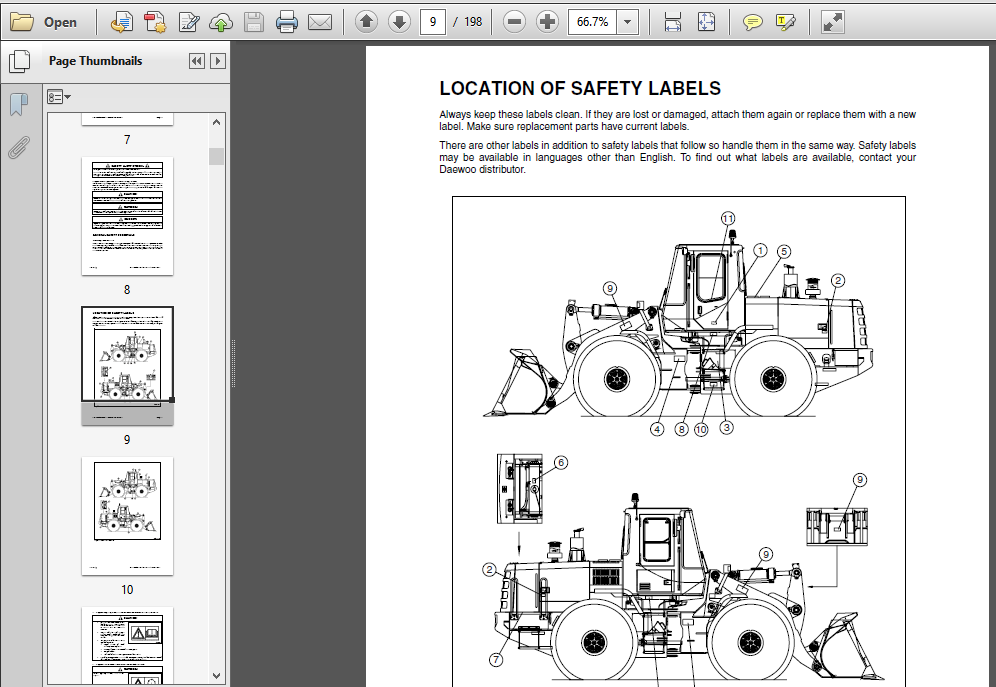
LOCATION OF SAFETY LABELS :
Always keep these labels clean. If they are lost or damaged, attach them again or replace them with a new label. Make sure replacement parts have current labels. There are other labels in addition to safety labels that follow so handle them in the same way. Safety labels may be available in languages other than English. To find out what labels are available, contact your Daewoo distributor.
TABLE OF CONTENTS:
Daewoo Doosan Mega 250 V Loader Operation Maintenance Manual
Safety 1-1
To the Operator of a Daewoo Wheel Loader 1-1
General Safety Essentials 1-2
Location of Safety Labels 1-3
Unauthorized Modifications1-11
Work Site Precautions1-11
Operation1-13
Equipment 1-18
Maintenance1-22
Shipping and Transportation1-25
Operating Controls 2-1
Component Locations 2-2
Control Identification2-6
Steering Console and Pedals 2-7
Transmission Display2-14
Front Instrument Panel 2-16
Right Side Switch Panel 2-25
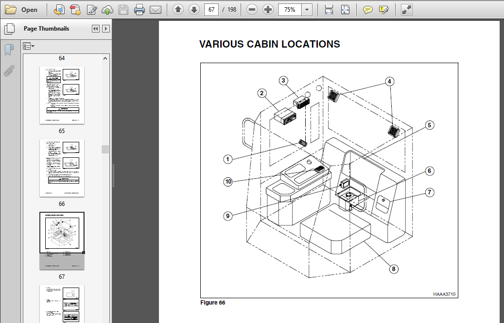
Various Cabin Locations2-35
Heater and Air Conditioner Operation 2-39
Stereo2-44
Seat Adjustment 2-48
Seat Belt2-50
Door Side Latch2-51
Fuse Box/Relay 2-52
Window Glass Breaking Tool2-55
Operation 3-1
Instrument Panel Control Functions 3-1
New Machine Break-in Procedures3-1
2 Table of Contents 022-00027AE Operation and Maintenance Manual
Engine Start and Stop3-2
Machine Travel 3-11
Machine Shut Down 3-13
Additional Braking 3-15
Boom Raise Kickout 3-16
Bucket Angle Indicator 3-16
Boom Lower Kickout (Option)3-17
Adjustment of Bucket Position Switch 3-17
Towing Machine3-18
If Engine Stalls While Traveling 3-19
Allowable Water Depth 3-19
Inspection, Maintenance and Adjustment 4-1
Preventive Maintenance 4-1
Table of Recommended Lubricants 4-3
Fluid Capacities4-5
Maintenance Intervals 4-6
10 Hour / Daily Service 4-8
50 Hour / Weekly Service4-18
250 Hour / Monthly Service4-25
500 Hour / 3 Month Service 4-34
1000 Hour / 6 Month Service 4-37
1,500 Hour / 9 Month Service 4-43
2,000 Hour / Yearly Service4-45
12,000 Hour / Six Year Service 4-48
Severe Conditions Maintenance4-49
General Maintenance4-50
Parking Brake Adjustment 4-52
Check Hydraulic Pressures 4-53
Tires and Wheels 4-57
Electrical System4-59
Bolt Torque Chart 4-60
Long Term Storage4-61
022-00027AE Operation and Maintenance Manual Table of Contents 3
Transportation 5-1
Loading Machine on a Trailer 5-1
Summary of Safety Precautions for Lifting 5-2
Troubleshooting 6-1
Engine 6-1
Hydraulic System 6-4
Travel System6-6
Steering6-11
Braking 6-12
Electrical System6-12
Specifications 7-1
General Specifications 7-1
Working Range and Dimensions7-4
Working Capacities 7-6
Approximate Weight of Workload Materials 7-6
Index 8-1
INDEX DETAILS:
Daewoo Doosan Mega 250 V Loader Operation Maintenance Manual
Numerics
10 Hour / Daily Service 4-8
1000 Hour / 6 Month Service 4-37
12,000 Hour / Six Year Service 4-48
1500 Hour / 9 Month Service 4-43
2000 Hour / Annually Service 4-45
250 Hour / Monthly Service 4-25
50 Hour / Weekly Service 4-18
500 Hour / 3 Month Service 4-34
A
Accelerator Pedal 2-10
Air Conditioner Refrigerant 4-42
Air Conditioning Filter 4-36, 4-41
Air Filter Indicator Light 2-20
Air Intake System
Air Cleaner – Clean 4-28
Check Air Intake System 4-17
Check Engine Air Pre-cleaner 4-26
Replace Outer Air Cleaner Element 4-43
Antifreeze 4-13
Applications 1-2
Attachment Precautions 1-11
Automatic Transmission Switch 2-34
Auxiliary Batteries 3-8
Axle Differential 4-33, 4-43
B
Battery
Auxiliary Batteries 3-8
Boost Starting 1-16
Condition 4-59
Long Term Storage 4-61
Warning Light 2-20
Bolt Torque Chart 4-60
Boom
Lower Kickout 3-17
Raise Kickout 3-16
Brake Accumulator 4-47
Brake Pedal 2-11
Brakes
Additional Braking 3-15
Bleeding 4-45
Brake Fluid Warning 2-22
Brake Fluid Warning Light 2-22
Brake Pedal 2-11
Troubleshooting 6-12
Bucket
Angle Indicator 3-16
Capacity 7-6
Position Switch 3-17
Teeth and Side Cutters 4-14
C
Cab Light 2-36
Cigar Lighter 2-29
Circuit Breaker 2-54
Clean Exterior of Radiator, Oil Cooler and Airconditioner
Evaporator 4-35
Cold Weather
Engine Start 3-5
Combination Switch 2-9
Component Locations 2-2
Conditions – Severe Maintenance 4-49
Cooling System
Antifreeze 4-13
Care 4-61
Coolant Level 4-13
Coolant Temperature Gauge 2-19
Coolant Temperature Warning Light 2-20
Radiator Coolant 4-37
Cracks and Faulty Welds 4-14
Cup Holder 2-32
D
Dismounting and Mounting Machine 1-14
Door Side Latch 2-51
Drive Shaft – Grease 4-31
E
Electric Box 2-37
Electrical System 4-59
Troubleshooting 6-12
Emergency Steering Switch 2-34
Engine
Check and Adjust Engine 4-42
Drive Belt Wear-Check 4-16
Fan Blade-Inspection 4-15
Oil Change 4-32
Oil Level Check 4-8
Oil Pressure Warning Light 2-20
Start 3-2
Stop 3-9
Troubleshooting 6-1
Ventilation 1-15
Water Pump Belt Tension 4-24, 4-30
Ergo-II Lever (Joystick) 2-27
F
Fire Hazard 1-16
Index 8-2 022-00027AE Operation and Maintenance Manual
Float Kick-out Switch 2-24
Fluid Capacities 4-5
Front Instrument Panel 2-16
Front Work Light Switch 2-30
Fuel Injection Priming Pump Strainer 4-41
Fuel System
Condensation – Draining 4-12
Filter-Replace 4-34
Gauge 2-17
Refill 4-11
Tank – Cleaning 4-40
Transfer Pump 4-50
Fuse Boxes 2-52
Fusible Link 2-54
G
Gauges
Coolant Temperature Gauge 2-19
Fuel Gauge 2-17
Hour Meter 2-18
Speedometer 2-18
Tachometer 2-18
Transmission Oil Temperature Gauge 2-19
General Specifications 7-1
Glass Breaking Tool 1-19
H
Hazard Warning Light Switch 2-23
Headlight Switch 2-30
Heater and Air Conditioner
Additional Operating Instruction 2-43
Blower Fan Switches 2-41
Fan and Air-Conditioner Switch 2-40
Memory Function of Used Mode 2-43
Selection Switch for Wind Direction 2-41
Temperature Control Switch 2-41
Ventilation Selection Switch 2-42
Heater and Air-conditioner
Control Panel 2-36
High Beam Indicator Light 2-21
Horn Button 2-8, 2-29
Hot/Cold Refrigerator 2-37
Hour Meter 2-18
Hydraulic System
Brake Charge Pressure 4-55
Check Oil Level 4-10
Control Lever Activation Pressure 4-55
Fan Motor Pressure 4-56
Full Flow Filter – Replace 4-24, 4-27
Hydraulic Oil – Replace 4-46
Hydraulic Pressures 4-53
Leaks in the Hydraulic System 4-10
Long Term Storage 4-61
Main Pump Pressure 4-53
Parking Brake Release Pressure 4-56
Service Brake Outlet Pressure 4-55
Steering Pump Pressure 4-54
System Pilot Filter – Replace 4-25
System Warm-up 3-10
System Warm-up – Cold Weather 3-10
Tank Water Draining 4-28
Transmission Clutch Pressure 4-54
Troubleshooting 6-4
Unloading Valve Pressure 4-53
I
Indicator Lights
Air Filter Indicator Light 2-20
Battery Warning Light 2-20
Brake Fluid Warning Light 2-22
Coolant Temperature Warning Light 2-20
Emergency Steering Indicator Light 2-23
Engine Oil Pressure Warning Light 2-20
High Beam Indicator Light 2-21
Left Turn and Hazard Warning Light 2-21
Parking Brake Indicator Light 2-22
Preheat Cycle Indicator Light 2-19
Right Turn and Hazard Warning Light 2-21
Work Light Indicator Light 2-21
Inspection, Maintenance and Adjustment 4-1
Instrument Panel Monitoring System 3-1
K
Kick-down Switch 2-12, 2-28
L
Leaks in Fuel System 4-11
Leaks in Hydraulic System 4-10
Left Turn and Hazard Warning Light 2-21
Levers
Adjusting Seat Forward/Backward 2-48
Adjusting Seat’s Angle 2-48
Angle Adjustment of Armrest 2-49
Backrest Adjustment 2-48
Ergo-II Lever (Joystick) 2-27
Log Forks Control Lever 2-26
Pilot Control Valve Lever (Joystick) 2-26
Steering Tilt Knob 2-10
Transmission Lever 2-12
Weight Adjustment Knob 2-48
Lifting Safety Precautions 5-2
Load Isolation System Switch 2-24
Loading Machine on a Trailer 5-1
Log Fork Control Lever 2-26
Long Term Storage 4-61
Lubricants 4-3
022-00027AE Operation and Maintenance Manual Index 8-3
M
Machine Shutdown 3-13
Machine Travel 3-11
Maintenance 1-22
Maintenance – General 4-50
Maintenance Intervals 4-6
Material Weight 7-6
Mounting and Dismounting 1-14
N
New Machine Break-in Procedures 3-1
O
Operation 1-13, 3-1
Outer Air Cleaner Element 4-43
P
Parking Brake Adjustment 4-52
Parking Brake Indicator Light 2-22
Parking Brake Switch 2-32
Parking Machine 1-17
Pilot Control Valve Lever (Joystick) 2-26
Pilot Cut-off Switch 2-33
Planetaries 4-33, 4-43
Preheat Cycle Indicator Light 2-19
Pre-start Safety Check 1-14
Preventive Maintenance 4-1
R
Rear Wiper Switch 2-31
Rear Work Light Switch 2-31
Refrigerator-Cold/Hot 2-37
Regulations, Local 1-13
Relay 2-54
Right Turn and Hazard Warning Light 2-21
Rotating Light (Beacon) 2-32
S
Safety 1-1
Safety Label Locations 1-3
Safety Precautions 4-2
Seat Adjustment
Adjusting Seat Forward/Backward 2-48
Adjusting Seat’s Angle 2-48
Angle Adjustment of Armrest 2-49
Backrest Adjustment 2-48
Headrest 2-49
Weight Adjustment 2-48
Seat Belt 2-50
Serial Numbers 4-1
Shipping and Transportation 1-25
Shut Down
Engine Shut Down 3-9
Machine 3-13
Shutdown Control Functions 1-18
Sloping Terrain 1-12
Speakers 2-36
Speedometer 2-18
Starter Switch 2-8
Start-up
Cold Weather Engine Start 3-5
Engine Start 3-2
Hydraulic System Warm-up 3-10
Hydraulic System Warm-up – Cold Weather
3-10
Starting with Auxiliary Batteries 3-8
Steering
Troubleshooting 6-11
Steering Tilt Knob 2-10
Steering Wheel 2-11
Stereo 2-36, 2-44
AM/FM Band Selection 2-45
Automatic Memory (AME) 2-45
Automatic Selection 2-45
Balance / Fader Control 2-44
Bass / Treble Control 2-44
Care of Stereo 2-46
Cassette Slot 2-45
Dolby B Selection 2-45
LCD Display Panel 2-46
Metal Selection 2-46
On-Off / Volume Control Knob 2-44
Play Direction Button 2-45
Speaker 2-36
Stereo System 2-44
Tape Eject Button 2-45
Storage Box 2-37
Switches
Automatic Transmission Switch 2-34
Blower Fan Switches 2-41
Combination Switch 2-9
Emergency Steering Switch 2-34
Float Kick-out Switch 2-24
Front Work Light Switch 2-30
Hazard Warning Light Switch 2-23
Headlight Switch 2-30
Heater and Air Conditioner Ventilation
Selection Switch 2-42
Heater and Air-Conditioner Fan Switch 2-40
Heater and Air-Conditioner Selection Switch
for Wind Direction 2-41
Horn Button 2-8
Kick-down Switch 2-12, 2-28
Load Isolation System Switch 2-24
Parking Brake Switch 2-32
Pilot Cut-off Switch 2-33
Rear Wiper Switch 2-31
Rear Work Light Switch 2-31
Index 8-4 022-00027AE Operation and Maintenance Manual
Rotating Light (Beacon) 2-32
Starter Switch 2-8
Temperature Control Switch 2-41
Transmission Cut-off Switch 2-33
T
Tachometer 2-18
Tipping Load 7-6
Tires and Wheels 4-57
Towing Machine 3-18
Transmission
Cut-off Switch 2-33
Display 2-14
Error Codes 6-8
Lever 2-12
Oil – Drain and Replace 4-33, 4-39
Oil Filter Replacement 4-33, 4-39
Oil Level Check 4-9
Oil Temperature Gauge 2-19
Travel Precautions 1-17
Travel System
Troubleshooting 6-6
Troubleshooting 6-1
U
Unauthorized Modifications 1-11
V
Visibility 1-16
W
Washer Tank 2-37
Water Pump Belt Tension 4-24, 4-30
Weight of Workload Materials 7-6
Wheel Nut Torque 4-57
Window Glass Breaking Tool 1-19, 2-55
Window Washer Liquid 4-14
Work Area 1-13
Work Light Indicator Light 2-21
Working Capacities 7-6
PLEASE NOTE:
- This is the SAME exact manual used by your dealers to fix your vehicle.
- The same can be yours in the next 2-3 mins as you will be directed to the download page immediately after paying for the manual.
- Any queries / doubts regarding your purchase, please feel free to contact [email protected]


