Daewoo Doosan Forklift BC20S to B30S-2 Service Manuals SB2034E02 – PDF DOWNLOAD
$29.95
Daewoo Doosan Forklift BC20S to B30S-2 Service Manuals SB2034E02 – PDF DOWNLOAD
Description
Daewoo Doosan Forklift BC20S to B30S-2 Service Manuals SB2034E02 – PDF DOWNLOAD
FILE DETAILS:
Daewoo Doosan Forklift BC20S to B30S-2 Service Manuals SB2034E02 – PDF DOWNLOAD
Language :English
Pages :499
Downloadable : Yes
File Type : PDF
IMAGES PREVIEW OF THE MANUAL:
DESCRIPTION:
Daewoo Doosan Forklift BC20S to B30S-2 Service Manuals SB2034E02 – PDF DOWNLOAD
SAFETY
The serviceman or mechanic may be unfamiliar with many of the systems on this machine. This makes it important to use caution when performing service work. A knowledge of the system and/or components is important before the removal or disassembly of any component. Because of the size of some of the machine components, the serviceman or mechanic should check the weights noted in this Manual, Use proper lifting procedures when removing any components. Following is a list of basic precautions that should always be observed.
TABLE OF CONTENTS:
Daewoo Doosan Forklift BC20S to B30S-2 Service Manuals SB2034E02 – PDF DOWNLOAD
Contents:
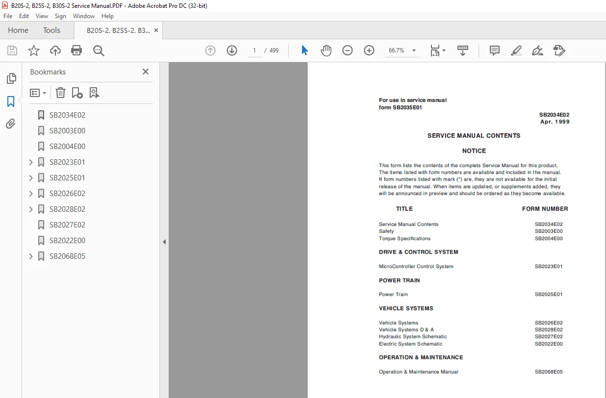
Safety SB2003E00
Torque Specifications SB2004E00
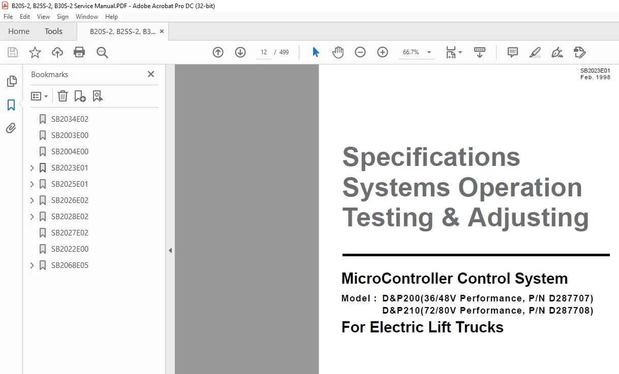
MicroController Control System SB2023E01
Power Train SB2025E01
Vehicle Systems SB2026E02
Vehicle Systems D & A SB2028E02
Hydraulic System Schematic SB2027E02
Electric System Schematic SB2022E00
Operation & Maintenance Manual SB2068E05
SB2034E02 1
SB2003E00 2
SB2004E00 4
SB2023E01 12
Index 15
Specifications 17
Component Measurements 17
Console 19
Contactors 20
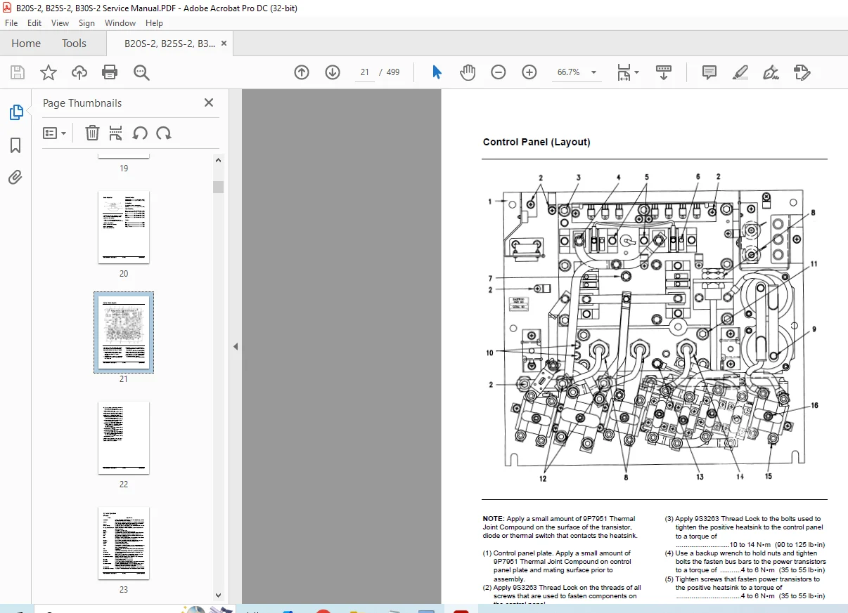
Control Panel (Layout) 21
Current Measurements 17
Direction Switch 19
Display Layout 19
Fuses 20
Head Capacitor 20
Instrument Panel 19
Thermal Switch 20
Transistor Connections 18
Transistor Measurements 18
Systems Operation 23
Accessory Circuits 37
DC-DC Converter 37
Horn Circuit 37
Hour Meter Circuit 37
Actuation Circuit 38
Capacitor Charging Circuit 39
Drive Circuit 51
Bypass Circuit 56
Control Circuit 51
Current Limit 55
Electrical Braking (Regenerative and Plugging) 59
Failure Protection Circuit 64
Field Shunt Circuit 57
Flyback Circuit 54
Power Circuit 52
Thermal Protection Circuits 64
General Information 30
Glossary 23
Hydraulic Pump Motor Circuit 40
Flyback Circuit 46
Lift Control Circuit 47
Lift Power Circuit 48
Power Steering Circuit 40
Power Steering Idle 41
Power Steering in Use 45
Shunt Field Circuit 44
Tilt and Auxiliary Control Circuit 50
Location of Control Panel
Components 28
Logic Unit 30
Battery Selection Jumpers 31
Operational Circuit Elements 32
Accelerator Control 36
Battery Discharge Indicator (BDI) 32
Central Vehicle Monitoring System 32
Contactors 36
Current Sensor 35
CVMS International Pictorial Symbols 34
On Board “Run Time” Diagnostics
(Fault Detection) 32
Resistor (Charging) 36
Wait Mode 35
Symbol Library 27
Testing And Adjusting 65
Built-In Diagnostic Operation 68
Accessing Stored Error Codes 74
Erased Stored Error Codes 74
Quick Diagnostic Procedure 75
“Run Time” Diagnostics
(Lift Truck in Operation) 69
“Self” Diagnostics (Lift Truck not in Operation) 70
Stored Error Codes 74
Component Tests129
Accelerator Control131
Capacitor (Head)131
Central Vehicle Monitoring System
(CVMS) Self Test132
Conductor and Switch Continuity131
Contactor (Bypass and Field
Shunt Activation)133
Contactor Components133
Current Sensor135
DC-DC Converter136
Diode Replacement136
Diodes136
Display (CVMS)133
Driver Board (On Vehicle)137
Driver Board (Off Vechicle)142
Logic Unit Quick Reference Voltage Check129
Resistor (Charging)147
Resistor (Regen)147
Resistors (R322 and R312)146
Thermal Switch148
Transistors T1P, T2P, T1D and T2D144
Transistor Replacement T1P, T2P, T1D and T2D145
Valve Control Card146
Control and Power System Operational Checks 67
Electrical System Adjustments149
Accelerator Control Linkage149
Battery Discharge Indicator (BDI) Adjustment154
Bypass Dropout Adjustment
– Stall Protection158
Current Limit Test and Adjustment156
Electrical Braking (Regen and Plugging) Current Test and Adjustment157
Field Shunt Pickup Test and Adjustment156
Lift Sensor150
Parking Brake Switch149
Rapid Tune-Up Procedure153
Tilt and Auxiliary Speed Adjustment152
Tilt and Auxiliary Switches152
Valve Control Card Adjustment151
Preparation Tests and Checks 65
Options159
Activating Default Settings164
Option Switches159
Programmable Features160
System Tests and Adjustments125
Discharging Head Capacitor(HEAD CAP)126
Logics Removal126
“Run Time” Tests127
Test Equipment125
Troubleshooting 65
Troubleshooting Check List 65
Troubleshooting Problem List 76
SB2025E01165
Index168
Systems Operation170
Drive Motor171
Final Drive173
General Information170
Power Transfer Group172
Testing And Adjusting174
Drive Motor179
Armature Terminal Test184
Armature Tests180
Brush Holder Test184
Brush Life Estimate185
Commutator Inspection182
Field Coil and Terminal Tests183
Motor Brushes179
Thermal Switch Tests185
Final Drive192
Wheel Bearing Adjustment192
Power Transfer Group Adjustments186
Pinion Bearing Adjustment189
Pinion Depth Check189
Pinion Installation187
Power Transfer Group186
Power Transfer Group Bearing and Gear Clearance (Backlash) Adjustments190
Troubleshooting174
Checks During Operation174
Drive Motor174
Power Transfer Group and Final Drive178
Visual Checks174
Specifications193
Drive Axle Mounting Group198
Drive Motor195
Drive Tire Installation198
Final Drive197
General tightening torque193
Power Transfer Group196
Disassembly & Assembly201
Brakes, Brake Adjuster And
Wheel Cylinder201
Final Drives And Hubs210
Oil Cooled Disc Type Brake213
Power Transfer Group204
SB2026E02215
Index218
Systems Operation220
Brake System232
Master Cylinder232
Oil Cooled Disc Brakes233
Parking Brake234
Shoe Type Brakes232
Electric Motors235
Hydraulic Pump Motor235
Hydraulic System220
Basic Schematic220
Hydraulic Control Valve222
Lift Cylinders and Mast225
Steering System228
Schematic228
Steering Cylinder229
Steering Gear230
Testing and Adjusting237
Brake System265
Brake Adjustment266
Brake System Air Removal265
Parking Brake Adjustment268
Parking Brake Control Group
Adjustment269
Parking Brake Test268
Pedal Adjustment267
Hydraulic Pump Motor270
Armature Tests271
Brush Holder Test275
Brush Life Estimate276
Commutator Inspection273
Field Coil and Terminal Tests274
Motor Brushes270
Shunt Field Tests275
Thermal Switch (Thermostat) Tests276
Hydraulic System248
Flow Control Valve Adjustment249
Relief Valve Pressure Check248
Standard Lift Cylinder Air Removal249
Mast and Carriage251
Carriage Adjustment256
Carriage and Mast Height Adjustment259
Chain Adjustments257
Chain Wear Test258
Drift Test261
Forks Parallel Check259
Mast Adjustment251
Tilt Cylinder Alignment260
Steering System262
Steering Axle Stop Adjustment263
Steering Knuckle Bearing Preload
Adjustment263
Steering System Pressure Check264
Steer Wheel Bearing Adjustment262
Troubleshooting237
Brake System242
Brake System (Oil Cooled Disc Type)243
Electric Motors244
Hydraulic System and Mast237
Steering System241
Visual Checks237
Specifications277
Brakes290
Carriage282
Hydraulic Control Valve277
Hydraulic Pumps278
Hydraulic Pump Motor292
Lift and Tilt Mounting Group286
Lift Cylinders279
Standard279
Full Free Triple Lift and Full Free
Lift Primary279
Full Free Triple Lift And Full Free
Lift Secondary280
Lift Relay Group – Standard Lift283
Lift Relay Group – Full Free Lift284
Lift Relay Group – Full Free Triple Lift285
Mast282
Parking Brake291
Priority Valve287
Priority Valve (Incorporated
with hydraulic pump)287
Steer Axle and Wheel289
Steering Gear288
Steering Wheel287
Steer Tire Installation289
Tilt Cylinders281
SB2028E02294
Index297
Accelerator Control Switch355
Backrest301
Carriage301
Control Panel360
Counterweight361
Drive Motor357
Forks301
Hydraulic Control Valves336
Hydraulic Control Valve Switch Group299
Hydraulic Pump Motor299
Mast307
Master Cylinder354
Parking Brake355
Primary Lift Cylinder326
Secondary Lift Cylinders323
Standard Lift Cylinders320
Steer Axle353
Steering Column350
Steering Cylinder333
Steering Unit340
Steering Wheel350
Tilt Cylinders329
Transaxle359
SB2027E02362
SB2022E00364
SB2068E05368
Table of Contents370
Information Section371
Foreword371
Safety Section373
Important Safety Information373
Safety373
Warning Signs and Labels374
General Hazard Information378
Operation Information380
Maintenance Information382
Crushing or Cutting Prevention382
Burn Prevention383
Fire or Explosion Prevention384
Operator Restraint System(If Equipped)385
Avoiding Lift Truck Tipovers389
Safety Rules391
How to Survive in a Tipover396
General Section398
Specifications398
Capacity Chart400
Capacity Chart – with SIDE SHIFTER402
Noise and Viration404
Serial Number404
Operator’s Warning and Identification Plate405
Operation Section407
Operator’s Station and Monitoring Systems407
Lift Truck Control413
Before Operating the Lift Truck417
Lift Truck Operation420
Operating Techniques423
Parking the Lift Truck426
Lift Fork Adjustment428
Storage Information429
Transportation Hints430
Towing Information431
Maintenance Section432
Inspection, Maintenance and Repair of Lift Truck Forks432
Torque Specifications436
Battery Discharge Indicator438
Battery439
Lubricant Specifications441
Cold Storage Applications443
Lubricant Viscosities and Refill Capacities445
Maintenance Intervals446
Quick Reference to Maintenance Schedule447
When Required448
Every 10 Service Hours or Daily465
First 50 – 100 Service Hours or a Week471
First 250 Service Hours or a Month472
Every 250 Service Hours or Monthly473
Every 500 Service Hours or 3 Months478
Every 1000 Service Hours or 6 Months483
Every 1500 Service Hours or 9 Months489
Every 2000 Service Hours or Yearly490
Every 2500 Service Hours or 15 Months495
Environment Protection Section496
Environment Protection496
Index Section497
Index497
S.M 18/2/2025