

Cnh Engines F5c Tier 3 F5a Tier 3 Service Manual
FILE DETAILS:
Cnh Engines F5c Tier 3 F5a Tier 3 Service Manual
FILE TYPE:PDF
MANUAL LANGUAGE:ENGLISH
DOWNLOADABLE:YES
PAGES:257
DESCRIPTION:
Cnh Engines F5c Tier 3 F5a Tier 3 Service Manual
This Manual is written for an expert technician to provide the technical information required to perform repair operations on this machine. Please read carefully this manual for the correct information regarding the repair procedures.This manual contains maintenance and repair procedures for the CNH ENGINES F5C TIER 3, F5A TIER 3. This service manual comes in PDF format. We recommend to use Adobe PDF Reader, to be sure all images / graphics will display correctly.
TABLE OF CONTENTS:
Cnh Engines F5c Tier 3 F5a Tier 3 Service Manual
General information – Section 1
Supply – Section 2
Industrial appliance – Section 3
Overhaul and specifications – Section 4
Tools – Section 5
SECTION 1
General specifications
Page
TECHNICAL CODING
ENGINE VIEWS
LUBRICATION SYSTEM
Oil pump
Engine oil filter
ENGINE OIL VAPOUR RECIRCULATION
ENGINE COOLING SYSTEM
WATER PUMP
THERMOSTAT
Working system
HEAT EXCHANGER
E.G.R. SYSTEM
(EXHAUST GAS RECIRCULATION)
INTERNAL EGR
EXTERNAL EGR
BOOSTING
SECTION 2
SUPPLY
PIPE LAYOUT
Working System Description
SUPPLY PUMP
Identification coding example
WORKING SYSTEM DESCRIPTION
Supply Phase
Delivery Phase
End of Delivery Phase
Engine Stop
L.D.A. Load Delivery Adjustment device
Working System
PRIMING PUMP
FUEL FILTER
SECTION 3
Industrial application
MAIN SPECIFICATIONS
PART ONE MECHANICAL COMPONENTS
ENGINE DISASSEMBLY ON BENCH
Cylinder 1 T.D.C. search
BOSCH VE 4/12F pump
Timing gearcase
Rear side component assembly
Flywheel assembly
Front side component assembly
Timing
Piston projection measurement
Checks and inspection
PART TWO ELECTRICAL EQUIPMENT
CABLE FOR ENGINES WITH EXTERNAL EGR SYSTEM
EGR (ELECTRONIC CONTROL UNIT) ELECTRICAL
LAYOUT
EGR Electronic Control Unit
Pin out EGR Electronic Control Unit
Engine cooling liquid temperature sensor
Oil pressure switch
KSB cooling liquid temperature sensor
Temperature and air pressure sensor
Engine drive shaft sensor
EGR solenoid valve
Capacity
Starter
PART THREE – DIAGNOSIS
DIAGNOSIS BY FAILURE
PART FOUR SCHEDULED MAINTENANCE
SCHEDULED MAINTENANCE
Servicing plan
Basic checking and maintenance operations
SECTION 4
Mechanical overhaul
GENERAL SPECIFICATIONS
DATA – ASSEMBLY SLACK
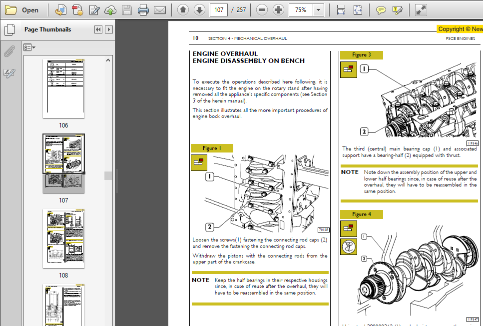
ENGINE OVERHAUL
ENGINE DISASSEMBLY ON BENCH
REPAIRS
CYLINDER UNIT
Checks and measurements
Checking head base surface on cylinder unit
TIMING
Camshaft
Cam lift and pin alignment check
BUSH
Bush replacement
Tappets
Tappet – Camshaft assembly
ENGINE DRIVE SHAFT
Main journals and crankshaft bearing pin measurement
Crankshaft bearing assembly
Main journal assembly slack measurement
Checking output shaft shoulder clearance
CONNECTING ROD-PISTON UNIT
Pistons
Piston diameter measurement
Piston pins
Conditions for the correct pin-piston coupling
Snap rings
Connecting rods
Bushes
Connecting rod-piston unit assembly
Connecting rod-piston coupling
Snap ring assembly
Connecting rod-piston unit fixing into cylinder barrel
Crankshaft bearing assembly slack measurement
Piston projection check
CYLINDER HEAD
Valve disassembly
Cylinder head base surface check
VALVES
Valve scaling, checking and grinding
VALVE GUIDE
Valve guide replacement
VALVE SEATS
VALVE SPRINGS
CYLINDER HEAD ASSEMBLY
Cylinder head reassembly
TIGHTENING TORQUE
SECTION 5
Tools
PART 2 – F5AE ENGINES
General information – Section 1
Supply – Section 2
Industrial appliance – Section 3
Overhaul and specifications – Section 4
Tools – Section 5
Safety rules
SECTION 1
General
TECHNICAL CODING
ENGINE VIEWS
LUBRICATION
Oil pump
Counterotating mass balancing device
Engine oil filter
ENGINE OIL VAPOUR RECIRCULATION
COOLING SYSTEM
WATER PUMP
THERMOSTAT
-Working system
HEAT EXCHANGER
TURBOCHARGING
EGR EXHAUST GAS RECIRCULATION
SECTION 2
Supply
SUPPLY
PIPE LAYOUT
Working System Description
SUPPLY PUMP
Identification coding example
WORKING SYSTEM DESCRIPTION
Supply phase
Delivery phase
End of delivery phase
Engine stop
L.D.A. Load Delivery Adjustment device
Working system
PRIMING PUMP
FUEL FILTER
SECTION 3
Industrial appliance
MAIN SPECIFICATIONS
PART ONE – MECHANICAL COMPONENTS
ENGINE DISASSEMBLY ON BENCH
BOSCH VE 4/12F pump
Timing gearcase
Rear side component assembly
Flywheel assembly
Front side component assembly
Timing
Piston projection measurement
Inspection and checks
Check of injection pump static advance on engine at the TDC of cylinder 1
PART TWO – ELECTRICAL EQUIPMENT
ELECTRIC CABLE TO CONNECT KSB WITH CERA
Engine cooling liquid temperature sensor
Oil pressure switch
KSB cooling liquid temperature sensor
Engine pulse transmitter
PART THREE – DIAGNOSIS
DIAGNOSIS BY FAILURE
PART FOUR – SCHEDULED MAINTENANCE
SCHEDULED MAINTENANCE
Servicing plan
Basic checking and maintenance operations
SECTION 4
Mechanical overhaul
GENERAL SPECIFICATIONS
DATA – ASSEMBLY SLACK
ENGINE OVERHAUL
ENGINE DISASSEMBLY ON BENCH
REPAIRS
CYLINDER UNIT
Checks and measurements
Checking head base surface on cylinder unit
TIMING
Camshaft
Cam lift and pin alignment check
BUSH
Bush replacement
Tappets
Tappet – Camshaft assembly
ENGINE DRIVE SHAFT
Main journals and crankshaft bearing pin measurement
Crankshaft bearing assembly
Main journal assembly slack measurement
Engine drive shaft shoulder slack check
CONNECTING ROD-PISTON UNIT
Pistons
Piston diameter measurement
Piston pins
Conditions for the correct pin-piston coupling
Snap rings
Connecting rods
Bushes
Connecting rod-piston unit assembly
Snap ring assembly
Snap ring fixing
Connecting rod-piston unit fixing into cylinder barrel
Connecting rod assembly slack measurement
Piston projection check
CYLINDER HEAD
Valve disassembly
Cylinder head base surface check
VALVES
Valve scaling, checking and grinding
VALVE GUIDE
Valve guide replacement
VALVE SEATS
VALVE SPRINGS
CYLINDER HEAD ASSEMBLY
Cylinder head assembly
TORQUE SETTING
SECTION 5
Tools
Section 1 describes the engines illustrating its features and working in general.
Section 2 describes the type of fuel feed.
Section 3 relates to the specific duty and is divided in four separate parts:
1. Mechanical part, related to the engine overhaul, limited to those components with different characteristics based on the relating specific duty.
2. Electrical part, concerning wiring harness, electrical and electronic equipment with different characteristics based on the relating specific duty.
3. Maintenance planning and specific overhaul.
4. Troubleshooting part dedicated to the operators who, being entitled to provide technical assistance, shall have simple and direct instructions to identify the cause of the major inconveniences.
Sections 4 and 5 illustrate the overhaul operations of the engine overhaul on stand and the necessary equipment to execute such operations.
The appendix contains a list of the general safety regulations to be respected by all installation and maintenance engineers in order to prevent serious accidents taking place.
The manual uses proper symbols in its descriptions; the purpose of these symbols is to classify contained information. In particular, there have been defined a set of symbols to classify warnings and a set for assistance operations.
SCREENSHOT OF THE MANUAL:


VIDEO PREVIEW:

PLEASE NOTE:
⦁ This is the SAME manual used by the dealers to troubleshoot any faults in your vehicle. This can be yours in 2 minutes after the payment is made.
⦁ Contact us at [email protected] should you have any queries before your purchase or that you need any other service / repair / parts operators manual.


Santana Edward –
Great results.Would recommend to others.