Challenger Operator’s Manual For 654C 658C Combine Series – PDF DOWNLOAD
Original price was: $89.95.$29.95Current price is: $29.95.
Challenger Operator’s Manual For 654C 658C Combine Series – PDF DOWNLOAD
No. D3161100M5 – S/N 580000026 – S/N
581000014
Description
Challenger Operator’s Manual For 654C 658C Combine Series – PDF DOWNLOAD
IMAGES PREVIEW OF THE MANUAL:


DESCRIPTION:
Challenger Operator’s Manual For 654C 658C Combine Series – PDF DOWNLOAD
No. D3161100M5 – S/N 580000026 – S/N
581000014
Preface
This Manual :
The purpose of this manual is to enable the owner/operator to handle and maintain the combine efficiently. Time spent in becoming familiar with the Operator’s Manual now will save time in the field. Wide variations in operation conditions make it impossible for the Company to make comprehensive or definite statements in its publications concerning performance and the use of its machines, or to accept liability for any damage which may result from errors or omissions.
- The specifications and illustrations contained in this manual pertain to combines manufactured for specific countries. Due to differing laws and requirements in various countries, some apparent discrepancies may result between any particular combine and those depicted in this manual.
- Some accessories and optional equipment appearing in this manual are not necessarily available in all territories. Technical specifications, dimensions and weights are without any obligation. Right to change technical specifications and equipment reserved. Front, rear, RH and LH are always seen in the travelling direction.
AGCO service :
- During the warranty period, all maintenance and repair work must be carried out by the AGCO dealer who will carefully carry out detailed checks of the progress and performance of the new combine. To obtain best results from an AGCO combine, it is important to continue regular servicing and periodical inspection after the warranty has expired.
- All major overhaul work on the combine must be carried out by a local AGCO dealer; an experienced technician will detect any problems which may arise between two overhauls. Mechanical staff regularly follow training courses to update their knowledge of the product, maintenance and repair techniques and the use of special modern tools and equipment for troubleshooting. They receive regular Service Bulletins and have access to all the workshop manuals and technical publications required to carry out repairs or maintenance meeting the quality standards required by AGCO.
TABLE OF CONTENTS:
Challenger Operator’s Manual For 654C 658C Combine Series – PDF DOWNLOAD
1 General Information 11
1 1 Dear Customer 13
1 1 1 Appropriate Use 13
1 1 2 Changes and Improvements 13
1 1 3 Directives 13
1 1 4 Preface 14
1 1 5 EC Declaration of Conformity for Combine and Table 15
1 1 6 Product Identification 18
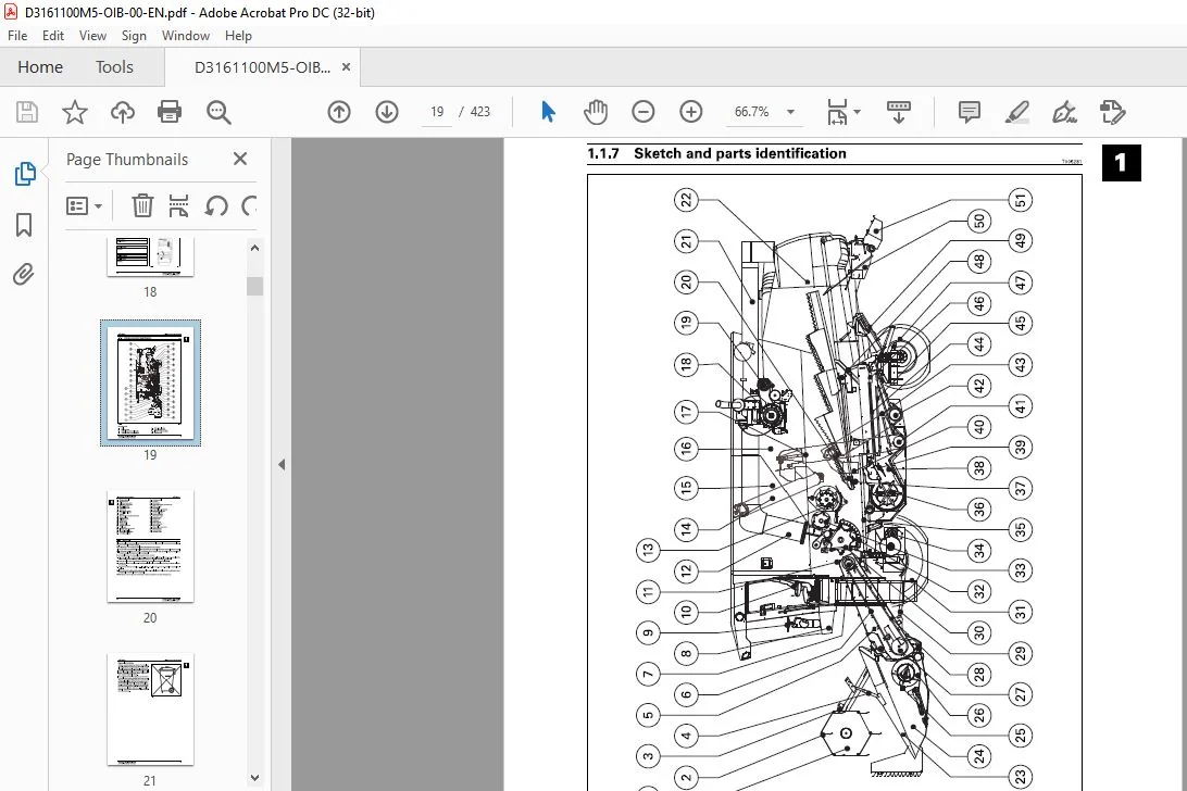
1 1 7 Sketch and parts identification 19
1 1 8 Disposal 20
2 Safety 23
2 1 Safety 25
2 1 1 General Safety Precautions 25
2 1 2 Attention – Warning Symbols 25
2 1 3 Safety Precautions 25
2 1 4 Road Transport 27
2 1 5 Warning/Instruction decals 28
2 1 6 CE Marking and Type Plate on the Combine 31
2 1 7 Position of CE Markings and Type Plate 40
3 Operation, Controls and Cab 45
3 1 Before start 4 7
3 1 1 Before start 47
3 2 Operator cab 49
3 2 1 Arrangement and Controls 49
3 2 2 Optional Extra 50
3 3 Safety Precautions – on the Move 51
3 3 1 Safety Precautions – on the Move 51
3 4 Starting and Stopping the Engine 52
3 4 1 Starting the Engine 52
3 5 Drive Controls 54
3 5 1 Multifunction lever 54
3 5 2 Adjustable armrest and control panel 55
3 5 3 Gearshift 56
3 5 4 Reduced engine revolutions in road transport (Speed Matching System) 57
3 5 5 Steering column 57
3 5 6 Brakes 58
3 6 Seats 59
3 6 1 Adjustment of Operator Seat 59
3 6 2 Adjustment of Air-Suspended Seat 59
3 6 3 EF declaration of conformity for the operator seat 60
3 6 4 Safety switch in operator seat – (Operator Present Switch) 61
3 6 5 Safety belt 62
3 6 6 Passenger seat 62
3 7 Mirrors 63
3 7 1 Electrically adjustable rearview mirrors 63
3 8 Accessibility 64
3 8 1 Ladder for Cab 64
3 8 2 Ladder for Engine Compartment 64
3 8 3 Cleaning the Windscreens 66
Challenger 654C – 658C – EAME
D3161100M5 – SIN 580000026 – SIN 581000014
3
Table of contents
3 9 Emergency situations 67
3 9 1 Emergency Exit 67
3 9 2 Fire extinguisher 68
3 10 Light and Lamps 69
3 10 1 Lights 69
3 10 2 Main Light and Work Light 70
3 11 Climate control 71
3 11 1 Maintenance and overview 71
3 11 2 Operation of Climate Control 72
3 12 Printer 74
3 12 1 Exchanging Paper and Ribbon in Printer 74
3 12 2 Inserting the Paper Roll 74
3 12 3 Fitting the Ribbon 75
3 13 Optional Extra 76
3 13 1 Four-Wheel Drive 76
3 13 2 Reversing camera 77
3 13 3 Auto-Steering 78
4 Operation, DATA VISION 79
4 1 Safety precautions 81
4 1 1 Safety precautions, Operating DATAVISION 81
4 2 DATAVISION 82
4 2 1 DATAVISION, general description 82
4 2 2 Operating DATAVISION on Terminal 84
4 2 3 Operating the Terminal by Remote Control in the Multi-Function Lever 85
4 2 4 Contrast and Brightness Control 86
4 2 5 Cleaning of terminal 86
4 2 6 Data card 87
4 2 7 DATAVISION menu structure 87
4 3 Harvest menu 89
4 3 1 Instrument reading 89
4 4 Main Menu 93
4 4 1 Main Menu Structure 93
4 5 Monitoring 95
4 5 1 Monitoring in general 95
4 5 2 Shaft Speeds 96
4 5 3 Engine monitoring/alarm 96
4 5 4 Engine Safety Alarm 96
4 5 5 Information 97
4 5 6 Shaft speeds 98
4 6 Harvesting Data 99
4 6 1 Standard data 99
4 6 2 Data logging in general 100
4 6 3 Using Data Logging 101
4 6 4 Data logging setup 108
4 6 5 Using Markers 111
4 7 Operator’s Manual 112
4 7 1 Harvest Settings 112
4 7 2 Routine servicing 113
4 7 3 DATAVISION 113
4 8 Diagnostics 114
4 8 1 Troubleshooting in DATAVISION 114
4 9 Coding 120
4 9 1 Coding in general 120
4 9 2 Clock Adjustment 121
4 9 3 Language 121
4 9 4 Area Measuring 121
4 9 5 Table Calibration 123
4 9 6 Returns Volume 124
4 9 7 Grain loss monitor 124
4 9 8 Shaft alarm calibration 124
4 9 9 Concave Calibration 124
4 Challenger 654C – 658C – EAME
D3161100M5 – SIN 580000026 – SIN 581000014
Table of contents
4 9 10 Constant Flow 124
4 9 11 Coding of electrical straw deflectors 125
4 9 12 Lead Time and Lag Time 127
4 9 13 Calibration of actuator for electrical sieves 128
4 10 Settings 129
4 10 1 Harvest Settings 129
4 10 2 Table settings 132
4 10 3 Machine settings 134
4 11 Returns Volume Monitor 137
4 11 1 Returns volume 137
4 11 2 Coding 137
4 12 Grain Loss Monitoring 139
4 12 1 Sensors 139
4 12 2 Adjustment of Grain Loss Sensors 139
4 13 Shaft Alarm Limits 141
4 13 1 Shaft alarm calibration 141
4 14 Yield meter 142
4 14 1 Yield meter (isotopic) 142
4 14 2 Micro-Trak Yield Meter 144
4 14 3 Yield Meter Calibration 146
4 15 Moisture meter 148
4 15 1 Limitations in the use of the moisture meter 148
4 15 2 Continuous Moisture Measuring 148
4 15 3 Measuring Principle 148
4 15 4 Using the Moisture Meter 149
4 15 5 Cleaning the Moisture Meter, 149
4 15 6 Calibration of moisture meter 150
4 16 Cutting height control 152
4 16 1 Adjustment and Operation of Cutting Height Control 152
4 16 2 Coding the Table 155
4 17 Field pressure control 156
4 17 1 Adjustment and operation of field pressure control 156
4 18 Interaction between the Table Controls 158
4 18 1 Table Controls, an outline 158
4 19 Auto Level table 160
4 19 1 Principle of Auto Level Table 160
4 19 2 Bleeding 161
4 19 3 Coding of Auto Level Table 162
4 19 4 Calibration of Table Angle 162
4 20 Operation of Auto Level Table 164
4 20 1 Using the Auto Level table 164
4 21 Ground sensors 166
4 21 1 Checking and Adjusting the Ground Sensors 166
4 22 Constant Flow 168
4 22 1 Constant Flow functional description 168
4 22 2 Start-up and Adjustment of Constant Flow 169
4 22 3 Constant Flow Engagement 171
5 Engine 173
5 1 Safety precautions 175
5 1 1 Safety Precautions, Engine 175
5 2 Engines 176
5 2 1 Engine types 176
5 3 Air-Intake 177
5 3 1 Filter System 177
5 4 Cooling System 178
5 4 1 Rotary Screen and Dust Aspirator 178
5 4 2 Coolers 178
5 4 3 Coolant 179
5 4 4 Checking the fan belt tension 179
5 4 5 Checking the water pump belt 180
Challenger 654C – 658C – EAME
D3161100M5 – SIN 580000026 – SIN 581000014
5
Table of contents
5 5 Fuel system 181
5 5 1 Fuel and quality requirements 181
5 5 2 Fuel system 182
5 5 3 Filter change 183
5 5 4 Bleeding the fuel system 184
5 6 SCR 185
5 6 1 The SC R system in general 185
5 6 2 Components and functions 186
5 6 3 Filling and storing AdBlue 187
5 6 4 Filter change 188
5 6 5 SC R system failure 189
5 7 Crankcase ventilation 190
5 7 1 Closed crankcase ventilation 190
5 8 Engine oil/change 191
5 8 1 Oil and Filter Change 191
5 9 Cleaning 192
5 9 1 Cleaning of engine compartment 192
5 10 EEM4 engine control 193
5 10 1 Electronic Engine Management and Monitoring 193
5 10 2 Engine Trouble Shooting (Self-Diagnosis) 194
5 10 3 EEM4 Codes 196
6 Cutting Tables 209
6 1 Safety precautions 211
6 1 1 Safety Precautions, Cutting Tables 211
6 2 Attachment/Removal of Table 212
6 2 1 Attachment of Table, Standard and Auto Level 212
6 2 2 Removal of Table 213
6 2 3 Supports 214
6 3 Table trailer 215
6 3 1 Attachment of combine and trailer 215
6 3 2 Table Trailer Brakes 215
6 4 Reel 216
6 4 1 Reel Adjustment Up/Down, Fore/Aft 216
6 4 2 Bleeding 217
6 4 3 Reel Rotation 217
6 4 4 Reel tine bars 218
6 4 5 Adjustment of the Reel in the Table 218
6 5 Knife 219
6 5 1 Knife and knife drive 219
6 6 Feeding 220
6 6 1 Table auger 220
6 6 2 Cut-off strip and distribution strip 221
6 6 3 Replacement of Feathering Fingers 222
6 6 4 Auger Flight Extensions, 20-22-25-30′ Tables 222
6 6 5 Reversing 223
6 7 Transmission 224
6 7 1 PowerFlow table, knife drive and table auger 224
6 7 2 Slip Clutch for Table Auger 224
6 8 PowerFlow Table 225
6 8 1 PowerFlow belts 225
6 8 2 Inspection and Start-Up of Powerflow Belts 225
6 8 3 Adjustment of belts 226
6 8 4 Scrapers, front 226
6 8 5 Scrapers, Rear, and Adjustment of Bearing Housings 227
6 8 6 Table Bottom 227
6 8 7 Cleaning 228
6 9 Crop lifters 229
6 9 1 Using Crop Lifters 229
6 10 Vertical Knives, Rape Auger and Straw Dividers 230
6 10 1 Vertical knife 230
6 10 2 Mounting of Vertical Knife 230
6 Challenger 654C – 658C – EAME
D3161100M5 – SIN 580000026 – SIN 581000014
c::’? Table of contents
6 10 3 Rape auger 231
6 10 4 Folding torpedo dividers and bow dividers 231
6 10 5 Mounting of Straw Dividers 232
6 10 6 Adjustment of Torpedo Divider 232
6 11 Fixed Table Auger Fingers 233
6 11 1 Fitting of fixed table auger fingers 233
6 11 2 Using Fixed Table Auger Fingers 233
6 11 3 High Table Sides 233
6 12 Main crop elevator 235
6 12 1 Elevator Chain 235
6 12 2 Transmission for Table 236
6 12 3 Stone Trap 236
6 12 4 Initial Adjustment of Cutting Height Indication 237
7 Operation of Table and Threshing Unit 239
7 1 Safety precautions 241
7 1 1 Safety Precautions, Operation of Machine and Cutting Table 241
7 2 Operation of Table 243
7 2 1 Table Height and Table Automatic Control 243
7 2 2 Cutting Height Control 244
7 2 3 Field Pressure Control 245
7 2 4 Preset cutting height 246
7 2 5 Auto Level table 246
7 2 6 Table Engagement – Emergency Stop 247
7 3 Threshing Unit Transmission 248
7 3 1 Threshing unit engagement 248
7 3 2 Cylinder Variator 249
7 3 3 Turning Tool for Cylinder 249
7 4 Concave Setting, Electrically Adjustable 250
7 4 1 Operation of Concave 250
7 4 2 Concave Setting 250
7 5 Threshing 252
7 5 1 Concave filler plates 252
7 5 2 Straw walkers 252
7 5 3 Rear beater curtain 253
7 6 Straw Chopper and Spreader Hood 254
7 6 1 Straw chopper 254
7 6 2 Adjustment of spreader hood 255
7 6 3 Counter Knives and Cross Bar 256
7 6 4 Replacement of Knives 258
7 7 Fanning Mill and Sieves 259
7 7 1 Fanning mill 259
7 7 2 Shaker shoe 259
7 7 3 Shaker Shoe with Electrical Sieves 260
7 7 4 Manual Adjustment of Sieves 260
7 7 5 Cleaning of Sieves and Main Grain Pan 261
7 7 6 Cleaning the Sieves 262
7 7 7 Shaker Shoe Light 264
7 7 8 Special sieves 264
7 8 Internal Grain Transport 265
7 8 1 Auger Housing/Elevators 265
7 8 2 Returns thresher 265
7 8 3 Tank filling auger 266
7 8 4 Grain tank 267
7 8 5 Unloading auger 269
7 8 6 Unloading Auger Clutch 270
7 8 7 Unloading tube 271
7 9 Rotary Separator 272
7 9 1 Adjusting the revolutions 272
7 9 2 Concave setting 273
7 10 Straw hood 274
7 10 1 Alarm switch for straw hood blocked 274
Challenger 654C – 658C – EAME
D3161100M5 • SIN 580000026 • SIN 581000014
7
Table of contents
7 10 2 Light in straw hood 275
7 11 Chaff spreader 276
7 11 1 Setting 276
7 12 Maxi Spreader 278
7 12 1 Operation and Adjustment 278
7 12 2 Adjustment of Sensors 279
7 13 Maize Threshing 280
7 13 1 Maize threshing in general 280
7 13 2 Attachment of Maize Header 280
7 13 3 Area measuring 281
7 13 4 Main crop elevator 281
7 13 5 Concave/initial settings 282
7 13 6 Threshing cylinder 282
7 13 7 Rotary Separator 282
7 13 8 Shaker shoe 283
7 13 9 Straw walkers 283
7 13 10 Bottom auger cover plate 284
7 13 11 Scrapers 284
7 13 12 Rear beater curtain 284
7 13 13 Straw chopper 285
7 13 14 Maxi Spreader 285
7 14 Harvest settings 286
7 14 1 Harvest charts and settings 286
7 15 Threshing 288
7 15 1 Threshing directions 288
8 Transmissions 289
8 1 Safety precautions 291
8 1 1 Safety Precautions, Transmissions 291
8 2 Adjustment of Transmissions 292
8 2 1 General 292
8 2 2 Threshing unit clutch 292
8 2 3 Hydrostatic transmission 293
8 3 Transmissions 294
Rear beater 294
Table and crop elevator 294
Straw chopper 295
Threshing cylinder 296
Unloading auger 296
Shaker Shoe and Chaff Spreader Counter Drive, and Straw Walker Drive 297
Filling and Returns System Countershaft 298
Returns Elevator and Returns Thresher 298
Tank Filling Elevator and Tank Filling Auger 299
Dust aspirator 299
Rotary screen 300
Fanning mill 301
Rotary Separator 301
Alternator and fan 302
Climate control 302
8 4 Transmission Diagrams 303
8 4 1 Transmission diagram, left-hand side 303
8 4 2 Transmission Diagram, Right-Hand Side 305
9 Hydraulics 307
9 1 Safety precautions 309
9 1 1 Safety Precautions, Hydraulic System 309
9 2 Hydraulic System 310
9 2 1 Hydraulic system, standard combine 310
9 2 2 Hydraulic System, Four-Wheel Drive 311
9 3 Oil change 312
9 3 1 Draining and refilling hydraulic oil 312
B Challenger 654C – 65BC – EAME
D3161100M5 – SIN 580000026 – SIN 581000014
Table of contents
9 4 Filter Change 313
9 4 1 Filter change in general 313
9 4 2 Return Oil Filter 313
9 4 3 Storage of Hydraulic System 314
9 5 Auxiliary Hydraulics 315
9 5 1 Auxiliary hydraulics in general 315
9 5 2 Functions and Auxiliary Hydraulics 315
9 5 3 Reel adjustment fore/aft – up/down 315
9 6 Hydraulic diagrams 316
9 6 1 Hydraulics Diagram, Standard Combine 316
9 6 2 Hydraulics Diagram for Chaff Spreader 318
9 6 3 Hydraulics diagram for Maxi Spreader 319
1 0 Maintenance 321
10 1 Safety precautions 323
10 1 1 Safety Precautions, Maintenance 323
10 2 Undercarriage 325
10 2 1 Undercarriage in general 325
10 2 2 Wheel nut torques 325
10 2 3 Tyre pressure 325
10 3 Lubrication Intervals 327
10 3 1 Lubrication chart, time intervals 327
10 3 2 Lubrication chart, right- and left-hand side 330
10 3 3 Lubrication chart, main crop elevator and front axle 332
10 3 4 Lubrication points, left-hand machine side 333
10 3 5 Lubrication points, right-hand machine side 346
10 3 6 Lubricants and operating fluids 358
10 3 7 Preliminary service inspections 359
10 3 8 Maintenance required 360
10 4 Gaar Oil Change 363
10 4 1 Gearbox 363
10 4 2 Final drives 363
10 4 3 Right-angle gear for returns thresher 364
10 5 Climate control 365
10 5 1 Diagram for Climate Control System 365
10 5 2 Maintenance 365
10 6 Cleaning and Off-Season Storage 366
10 6 1 Cleaning 366
10 6 2 Off-season storage 367
10 6 3 Storage of Engine, Fuel System, SC R System and Hydraulic System 368
10 6 4 Periodical Start-Up 368
10 6 5 Removal of Crop Elevator 369
10 6 6 Removal of Elevator Chains 369
10 6 7 After Off-Season Storage 369
10 7 Adjustment of Brakes 370
10 7 1 Adjustment of Foot Brakes, Disc Brakes 370
10 7 2 Adjustment of parking brake 370
1 1 Electrical System 371
11 1 Safety precautions 373
11 1 1 Safety Precautions, Electric System 373
11 2 Electrical System 37 4
11 2 1 Charging system 374
11 2 2 Electric Boxes and Main Switch 375
11 2 3 External connectors 12V 376
11 3 Electro-Hydraulic System 378
11 3 1 Electro-Hydraulic System in General 378
11 4 Key to Signatures for Wiring Harness 379
11 4 1 Wire Codes 379
11 4 2 Component Codes 379
11 5 Overview, Electric Box and Cab 380
11 5 1 Position of Connectors in Electric Boxes 380
Table of contents
11 5 2 Fuses and Relays, Electric Box and Cab 381
11 6 Wiring diagrams 383
11 6 1 Key to symbols 383
11 6 2 Diagrams overview 384
11 6 3 Fuse ratings 384
11 6 4 Components 385
11 6 5 Wiring diagrams 394
1 2 Specifications 407
12 1 Specifications 409
12 1 1 Dimensions and specifications 409
Challenger
CHALLENGER OPERATOR’S MANUAL FOR 654C 658C COMBINE SERIES – PDF DOWNLOAD:
PLEASE NOTE:
- This is not a physical manual but a digital manual – meaning no physical copy will be couriered to you. The manual can be yours in the next 2 mins as once you make the payment, you will be directed to the download page IMMEDIATELY.
- This is the same manual used by the dealers inorder to diagnose your vehicle of its faults.
- Require some other service manual or have any queries: please WRITE to us at [email protected]
S.V