CAT Bucyrus RH 200 Hydraulic Excavator Operating Instruction Manual 3657530 – PDF DOWNLOAD
$28.95
CAT Bucyrus RH 200 Hydraulic Excavator Operating Instruction Manual 3657530 – PDF DOWNLOAD
Description
CAT Bucyrus RH 200 Hydraulic Excavator Operating Instruction Manual 3657530 – PDF DOWNLOAD
FILE DETAILS:
CAT Bucyrus RH 200 Hydraulic Excavator Operating Instruction Manual 3657530 – PDF DOWNLOAD
Language : English
Pages : 286
Downloadable : Yes
File Type : PDF
DESCRIPTION:
CAT Bucyrus RH 200 Hydraulic Excavator Operating Instruction Manual 3657530 – PDF DOWNLOAD
Preface:
These operating instructions are designed to fa- miliarize the operator with the machine
and its designated use.
- The operating instructions contain important in- formation on how to operate the machine
safely, properly and with maximum efficiency. Observing these instructions helps to
prevent hazardous situations, to reduce repair costs and downtimes and to increase the
reliability and service life of the machine. - The operating instructions must be supplemented by the respective national rules and
regulations for accident prevention and environmental protection. - The operating instructions must always be avail- able in the driver’s cab of the machine.
- The operating instructions must be read and put into practice by any person in charge
of carrying out work with or on the machine, such as
pro- duction waste and disposal of fuels and con- sumables,
- In addition to the operating instructions and the mandatory rules and regulations for
accident pre- vention and environmental protection in the user’s country and at the place
where the machine is to be used, the generally recognized technical rules for safe and
proper working must be observed [1].
[1] Complies with VDMA recommendation “Operating instruc- tions”
The operating instructions are directed to the con- struction-machine specialist. They cannot
provide basic know-how. This can be acquired, for exam- ple, in several days’ instruction by
a qualified O&K Mining mechanic or by attending an O&K Mining training course for
operators or maintenance per- sonnel. - The O&K-Mining after-sales service will be pleased to deal with any queries you
may have after reading through the operating instructions. - All O&K Mining operating manuals are issued in German and then translated. Even a good
transla- tion may give rise to questions which O&K Mining will be pleased to answer. - The operating instructions are not work instructions for carrying out major repairs. Such work is
willingly done for you by the O&K Mining after-sales serv- ice. - The documentation relating to the machine is listed according to scope, quantity and language in
the shipping note of the machine or in the covering letter if supplied separately. The operating
instruc- tions and spare-parts list are marked with the serial number of the machine. - On taking receipt of the consignment, please check that the documentation is complete and in the
language requested by you.
IMAGES PREVIEW OF THE MANUAL:
Customer Support: [email protected]
TABLE OF CONTENTS:
CAT Bucyrus RH 200 Hydraulic Excavator Operating Instruction Manual 3657530 – PDF DOWNLOAD
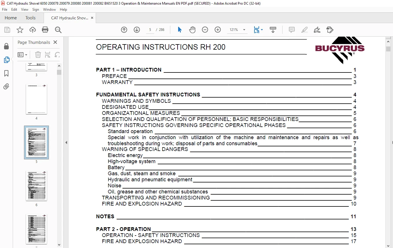
PART 1 – INTRODUCTION 1
PREFACE 3
WARRANTY 3
FUNDAMENTAL SAFETY INSTRUCTIONS 4
WARNINGS AND SYMBOLS 4
DESIGNATED USE 4
ORGANIZATIONAL MEASURES 5
SELECTION AND QUALIFICATION OF PERSONNEL; BASIC RESPONSIBILITIES 6
SAFETY INSTRUCTIONS GOVERNING SPECIFIC OPERATIONAL PHASES 6
Standard operation 6
Special work in conjunction with utilization of the machine and maintenance and repairs as well as
troubleshooting during work; disposal of parts and consumables 7
WARNING OF SPECIAL DANGERS 8
Electric energy 8
High-voltage system 8
Battery 8
Gas, dust, steam and smoke 9
Hydraulic and pneumatic equipment 9
Noise 9
Oil, grease and other chemical substances 9
TRANSPORTING AND RECOMMISSIONING 9
FIRE AND EXPLOSION HAZARD 10
NOTES 11
PART 2 – OPERATION 13
OPERATION – SAFETY INSTRUCTIONS 15
FIRE AND EXPLOSION HAZARD 17
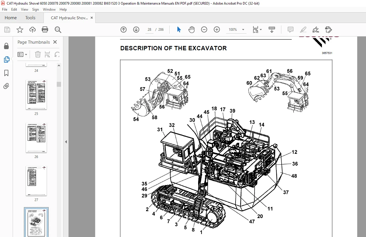
DESCRIPTION OF THE EXCAVATOR 18
Excavator layout 19
Undercarriage 20
Superstructure 20
Drive 20
Hydraulic system 20
Pump Managing System (PMS) 20
Stored Program Control (SPC) 20
Demand control / Zero-flow regulation 21
Automatic engine speed reduction 21
Board-Control-System (BCS) 21
Electrical system 21
Signs 23
Entering and leaving the machine Safety instructions 24
Ramp-type ladder (optional) 26
EMERGENCY STOP pushbuttons 28
Windscreen washer 28
Driver’s seat 29
Fire extinguisher 30
Automatic fire-extinguishing system (optional) 31
MONITORING, WARNING AND CONTROL ELEMENTS 32
PUTTING THE MACHINE INTO OPERATION 63
REFUELLING 63
Refuelling – Safety instructions 63
SERVICE STATION (TANKLIFT) 63
Switching the electrical system on and off 69
Starting and stopping the engines 70
Air conditioner (option) 73
Control panel (Greentop) 74
OPERATING INSTRUCTIONS RH 200
Control panel (Sigma) 74
Back-up heating (option) 75
Control panel (Eberpächer) 75
Control panel 76
DRIVING SAFETY INSTRUCTIONS 77
TRAVELLING 78
Superstructure basic position 78
Travelling forwards/backwards 78
Emergency machine drive 82
Locking the superstructure 84
Track parking brake 84
TRANSPORTING THE MACHINE 85
Transport – Safety instructions 85
WORKING OPERATION – SAFETY INSTRUCTIONS 87
WORKING OPERATION 89
Before starting work 89
Slewing and braking the superstructure 89
Braking the superstructure 89
Working 90
After daily operation 91
ASSEMBLING WORKING EQUIPMENT – SAFETY INSTRUCTIONS 93
Securing the machine 95
CORROSION PROTECTION FOR PINS AND BEARINGS (BUSHINGS AND HUBS) 96
NOTES 97
PART 3 INSPECTION AND SERVICING 99
INSPECTION AND SERVICING – SAFETY INSTRUCTIONS 101
FIRE AND EXPLOSION HAZARD 107
INSPECTION AND SERVICING PLANS – INSTRUCTIONS 109
Intervals 109
Change of engine oil l 109
Air-intake system 109
Oils / Greases 109
Cleaning jobs 109
Plan V – Once prior to initial commissioning 111
Plan V – Once prior to initial commissioning 112
Plan N – After initial commissioning and during the running-in period 113
Plan T – Every 10 OH or every working shift 115
Plan W – Every 60 OH or every working shift 115
Plan T – Every 10 OH or every working shift 116
Plan W – Every 60 OH or every working shift 116
Plan A – after every 250 OH 117
Plan B – after every 500 OH 117
Plan C – after every 1000 OH 117
Plan D – after every 5000 Bh 117
Plan E – after every 10000 OH 117
Plan A – after every 250 OH 118
Plan B – after every 500 OH 118
Plan C – after every 1000 OH 118
Plan D – after every 5000 Bh 118
Plan E – after every 10000 OH 118
Plan A – after every 250 OH 120
Plan B – after every 500 OH 120
Plan C – after every 1000 OH 120
Plan D – after every 5000 Bh 120
OPERATING INSTRUCTIONS RH 200
Plan E – after every 10000 OH 120
Plan A – after every 250 OH 121
Plan B – after every 500 OH 121
Plan C – after every 1000 OH 121
Plan D – after every 5000 Bh 121
Plan E – after every 10000 OH 121
Plan A – after every 250 OH 122
Plan B – after every 500 OH 122
Plan C – after every 1000 OH 122
Plan D – after every 5000 Bh 122
Plan E – after every 10000 OH 122
Plan A – after every 250 OH 123
Plan B – after every 500 OH 123
Plan C – after every 1000 OH 123
Plan D – after every 5000 Bh 123
Plan E – after every 10000 OH 123
Plan A – after every 250 OH 124
(at 250, 750, 1250 … OH) 124
Plan B – after every 500 OH 124
Plan C – after every 1000 OH 124
Plan D – after every 5000 Bh 124
Plan E – after every 10000 OH 124
Plan A – after every 250 OH 125
(at 250, 750, 1250 … OH) 125
Plan B – after every 500 OH 125
Plan C – after every 1000 OH 125
Plan D – after every 5000 Bh 125
Plan E – after every 10000 OH 125
LUBRICATING CHART – GREASE (LOADING BUCKET) 127
Lubricating chart – Grease / Loading bucket (legend) 128
Filling quantities – Grease 128
LUBRICATING CHART – GREASE (BACKHOE BUCKET) 129
Lubricating chart – Grease / Backhoe bucket (legend) 130
Filling quantities – Grease 130
INSPECTION PLAN – OIL 131
Inspection plan – Oil (legend) ) 132
Filling quantities – oil 133
Filling quantities – other 133
LUBRICANTS 133
I. OILS FOR COMBUSTION ENGINES AND COMPRESSORS (SELECTION) 133
II. OILS FOR HYDRAULIC SYSTEM (SELECTION) 134
III. OILS FOR GEARBOXES (SELECTION) 135
V. GREASES FOR BEARINGS AND SLEWING RINGS 136
SERVICING WORK 137
Hose line for oil and cooling liquid changes 137
ENGINE 138
Engine – Safety instructions 138
Checking the V-belt tension 138
Retensioning the alternator/fan belt 138
Checking and adjusting the valve clearance 138
Checking the engine oil level / Topping up 138
Checking the oil level in the engine oil reservoir /topping up (optional) 139
Changing the engine oil 140
Draining off engine oil 140
Draining the oil off the engine oil reservoir (optional) 142
Replacing the oil filter 143
OPERATING INSTRUCTIONS RH 200
Replacing the oil filter for engine oil reservoir (optional) 144
Eliminator filter and centrifuge 146
Centrifuge 146
COOLING SYSTEM 148
Temperature 148
Radiators 148
Cooling liquid 150
Water filter 153
AIR-INTAKE SYSTEM 154
Main filter elements 154
Checking and cleaning the main filter element 155
Safety filter element 156
Air-intake lines 157
Dust collection 157
FUEL SYSTEM 158
Fuel system – Safety instructions 158
Replacing the fuel filter 158
Venting the fuel system 159
Cleaning the fuel tanks 159
Water trap (option) 161
Servicing 161
ELECTRICAL SYSTEM 162
Electrical system – Safety instructions 162
Alternator – Instructions 162
Switchgear cabinet 165
Emptying the dust trap 165
HYDRAULIC SYSTEM 167
Hydraulic system – Safety instructions 167
Depressurizing the hydraulic system 167
Checking the hydraulic oil level / Topping up with oil 168
Changing the hydraulic oil return-flow (hydraulic oil reservoir) 170
Bypass valves 172
Breather filter 173
High-pressure filter for working hydraulics 174
High-pressure filter for servo circuit 175
High-pressure filter for feeding circuits and slewing pumps 176
High-pressure filters for slewing circuit 177
Changing the hydraulic oil 178
Venting the hydraulic system 181
Cleaning the hydraulic oil cooler 182
Pressure accumulator – Emergency lowering 183
Pressure-accumulator inspection regulations 183
Checking the gas charging pressure in the pressure accumulator 183
PUMP TRANSFER GEARBOX 185
Checking the gearbox oil level / Topping up with oil 185
Changing the gearbox oil 185
Gearbox venting 187
Pre-chamber 187
Pump transfer gearbox lube oil filters 188
SLEWING GEARBOX 189
Gearbox – Checking the oil level / Topping up with oil 189
Changing the gearbox oil 189
Gearbox venting 190
Slewing gear neck 190
OPERATING INSTRUCTIONS RH 200
TRAVEL GEARBOXES 191
Gearbox – Checking the oil level / Topping up with oil 191
Travel gearbox – Changing oil 193
CRAWLER TRACKS 196
Cleaning 196
Track rollers 196
Track rollers 197
Track and support rollers fastening 197
Track tensioner 198
Pressure-accumulator inspection regulations 199
Checking the gas charging pressure in the pressure accumulator 199
Idlers 200
SLEWING RING 201
Slewing ring – Instructions 201
Bearing races 201
Slewing ring – Checking the grease filling 202
Slewing ring – Filling in grease 202
Slewing ring – Checking the screws for tightness 202
CENTRAL LUBRICATING 203
Design and function 203
Unblocking a grease line. 206
Manual greasing (option) 206
OTHER MAINTENANCE 208
Engine 208
RAMP-TYPE LADDER (OPTIONAL) (OPTION) 209
Guide pulleys and locking bolt 209
Pressure-accumulator inspection regulations 210
Checking the gas charging pressure in the pressure accumulator 210
ON-BOARD CRANE (OPTIONAL) 211
Monitoring, warning and control elements 211
Checking the on-board crane 211
Drive unit 212
On-board crane 212
ALTERNATOR (OPTIONAL) 213
Drive unit 213
PUTTING OUT OF OPERATION AND RECOMMISSIONING 214
Putting the excavator out of operation 214
Battery storage 214
Recommissioning 214
NOTES 215
PART 4 – REPAIR WORK 217
REPAIR WORK – SAFETY INSTRUCTIONS 219
FIRE AND EXPLOSION HAZARD 221
ENGINE 223
ELECTRICAL SYSTEM 223
Assisted starting (with jumper cables) – Safety instructions 223
Assisted starting (with jumper cables) 224
HYDRAULIC SYSTEM 225
OPERATING INSTRUCTIONS RH 200
PRESSURE ACCUMULATORS – SAFETY INSTRUCTIONS 225
WELDING OPERATIONS 226
WELDING OPERATIONS – SAFETY INSTRUCTIONS 226
PART 5 – ANNEX 229
TROUBLESHOOTING 231
INSTRUCTIONS ON TROUBLESHOOTING 231
LAYOUT OF THE FAULT TABLE 231
Fault 231
Possible causes 231
Measures 231
Section 231
FAULT TABLES 232
Combustion engine – Fault table 232
Working hydraulics – Fault table 233
Track drive – Fault table 234
Slewing mechnism – Fault table 235
Central lubricating system – Fault table 236
HYDRAULIC CIRCUIT DIAGRAM 238
Legend (loading bucket) 238
HYDRAULIC CIRCUIT DIAGRAM 240
Legend (backhoe bucket) 240
TIGHTENING TORQUES AND ANGLES – TABLE 241
ABBREVIATIONS 243
ABBREVIATIONS 244
TECHNICAL DATA 245
PART 6 – INDEX 249
INDEX 251
PLEASE NOTE:
- This is not a physical manual but a digital manual – meaning no physical copy will be couriered to you. The manual can be yours in the next 2 mins as once you make the payment, you will be directed to the download page IMMEDIATELY.
- This is the same manual used by the dealers inorder to diagnose your vehicle of its faults.
- Require some other service manual or have any queries: please WRITE to us at [email protected]
S.V