

Case CX800B Crawler Excavators Service Manual 84172684C – PDF DOWNLOAD
DESCRIPTION:
Case CX800B Crawler Excavators Service Manual 84172684C – PDF DOWNLOAD
TABLE OF CONTENTS:
Case CX800B Crawler Excavators Service Manual 84172684C – PDF DOWNLOAD
1 GENERAL INFORMATION
Safety, general information and standard torque data………………………………. 1001 7-27691EN
General specifications and special torque setting ……………………………………. 1002 SM800B1002-1EN
2 ENGINE
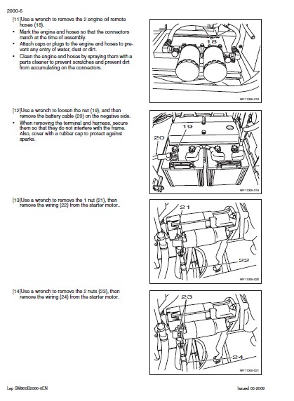
Removal and installation of the engine…………………………………………………… 2000 SM800B2000-0EN
Removal and installation of the fuel cooler, engine inter-cooler,
radiator and oil cooler ………………………………………………………………………….. 2001 SM800B2001-0EN
Removal and installation of the turbo charger …………………………………………. 2004 SM700B2004-0EN
Removal and installation of EGR cooler and EGR valve…………………………… 2005 SM700B2005-0EN
Removal and installation of the engine hood…………………………………………… 2006 SM700B2006-0EN
Engine specifications………………………………………………………………………………….*
Disassembly and assembly of the engine ……………………………………………………..*
3 FUEL SYSTEM
Removal and installation of the fuel tank………………………………………………… 3001 SM700B3001-0EN
Removal and installation of the supply pump and common rail …………………. 3004 SM800B3004-0EN
Removal and installation of the injectors ………………………………………………… 3005 SM800B3005-0EN
Fuel engine system ……………………………………………………………………………………*
4 ELECTRICAL SYSTEM
Service connector kit …………………………………………………………………………… 4000 SM350B4000-1EN
Electrical and engine functions and service support ………………………………… 4001 SM700B4001-1EN
Removal and installation of the starter motor ………………………………………….. 4004 SM700B4004-0EN
Removal and installation of the alternator ………………………………………………. 4005 SM700B4005-0EN
Electrical equipment & electrical circuit diagrams ……………………………………. 4020 SM800B4020-0EN
Engine error code (DTC) ……………………………………………………………………… 4021 SM700B4021-0EN
Main body error code (DTC)…………………………………………………………………. 4022 SM700B4022-0EN
Troubleshooting, 6WG1 engine …………………………………………………………….. 4023 SM700B4023-0EN
5 UNDERCARRIAGE
Removal and installation of tracks …………………………………………………………. 5001 SM700B5001-0EN
Rollers ………………………………………………………………………………………………. 5003 SM800B5003-0EN
Take-up roller……………………………………………………………………………………… 5005 SM700B5005-0EN
6 DRIVE TRAIN
Removal and installation of the drive motor and
final drive transmission…………………………………………………………………….. 6001 SM800B6001-0EN
Disassembly and assembly of the drive motor and
final drive transmission…………………………………………………………………….. 6002 SM800B6002-0EN
Removal and installation of the swing motor and
swing reduction gear ……………………………………………………………………….. 6003 SM800B6003-0EN
Disassembly and assembly of the swing reduction gear …………………………… 6004 SM800B6004-0EN
7 UNDERCARRIAGE HYDRAULICS
8 UPPERSTRUCTURE HYDRAULICS
Specifications, troubleshooting, checks and
hydraulic pressure settings………………………………………………………………..8001 SM800B8001-1EN
Removal and installation of the hydraulic reservoir …………………………………..8002 SM800B8002-0EN
Removal and installation of the main hydraulic pump………………………………..8003 SM700B8003-0EN
Removal and installation of the main hydraulic control valve………………………8004 SM800B8004-0EN
Removal and installation of the attachment cylinders………………………………..8005 SM800B8005-0EN
Removal and installation of the hydraulic swivel ……………………………………….8006 SM700B8006-0EN
Removal and installation of the pilot blocs……………………………………………….8007 SM700B8007-0EN
Disassembly and assembly of the main hydraulic pump ……………………………8010 SM700B8010-0EN
Disassembly and assembly of the main hydraulic control valve ………………….8011 SM700B8011-0EN
Disassembly and assembly of the attachment cylinders ……………………………8012 SM800B8012-0EN
Disassembly and assembly of the hand control levers ………………………………8013 SM130B8013-0EN
Disassembly and assembly of the foot control levers ………………………………..8014 SM800B8014-0EN
Disassembly and assembly of the cushion valve………………………………………8016 SM700B8016-0EN
Removal and installation of the safety valve …………………………………………….8017 SM800B8017-0EN
Disassembly and assembly of the swing motor ………………………………………..8019 SM700B8019-0EN
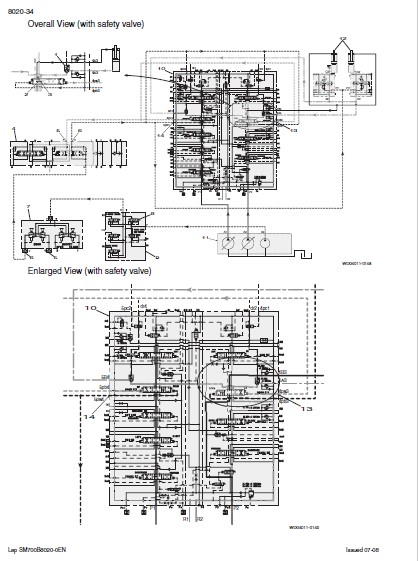
Hydraulic functions ………………………………………………………………………………8020 SM700B8020-0EN
Hydraulic component functions………………………………………………………………8030 SM700B8030-1EN
9 UPPERSTRUCTURE
Removal and installation of the counterweight …………………………………………9002 SM800B9002-0EN
Removal and installation of the boom, dipper and bucket ………………………….9003 SM800B9003-0EN
Removal and installation of the seat ……………………………………………………….9004 SM130B9004-0EN
Removal and installation of the cab and cab equipment ……………………………9005 SM130B9005-0EN
Air conditioner functions and troubleshooting…………………………………………..9006 SM700B9006-1EN
Air conditioning unit ……………………………………………………………………………..9007 SM800B9007-0EN
Air conditioning components………………………………………………………………….9009 SM700B9009-0EN
Removal and installation of the attachment, counterweight
and side frame…………………………………………………………………………………9010 SM800B9010-0EN
Large size hydraulic schematics …………………………………………………………. Pocket KUJ11060-E03
Large size electrical schematics …………………………………………………………. Pocket KWR10070-E04
IMAGES PREVIEW OF THE MANUAL:
VIDEO PREVIEW OF THE MANUAL:

PLEASE NOTE:
- This is the same manual used by the dealers to diagnose and troubleshoot your vehicle
- You will be directed to the download page as soon as the purchase is completed. The whole payment and downloading process will take anywhere between 2-5 minutes
- Need any other service / repair / parts manual, please feel free to contact [email protected] . We still have 50,000 manuals unlisted
S.V


