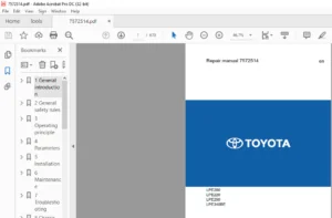
BT TOYOTA OSE100, OSE100W REPAIR MANUAL 7538992-040 – PDF DOWNLOAD
$29.95
BT TOYOTA OSE100, OSE100W REPAIR MANUAL 7538992-040 – PDF DOWNLOAD
Description
BT TOYOTA OSE100, OSE100W REPAIR MANUAL 7538992-040 – PDF DOWNLOAD
FILE DETAILS:
BT TOYOTA OSE100, OSE100W REPAIR MANUAL 7538992-040 – PDF DOWNLOAD
Language : English
Pages : 320
Downloadable : Yes
File Type : PDF
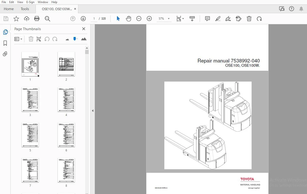
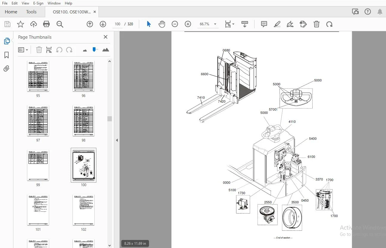
IMAGES PREVIEW OF THE MANUAL:
TABLE OF CONTENTS:
BT TOYOTA OSE100, OSE100W REPAIR MANUAL 7538992-040 – PDF DOWNLOAD
1. Contents.......................................................................................0
2. General introduction...........................................................................0
	2.1 How to use this manual....................................................................0
	2.2 Warning symbols...........................................................................0
	2.3 Pictograms................................................................................0
		2.3.1 Screws/Nuts.........................................................................0
3. General safety rules...........................................................................0
	3.1 Work safety...............................................................................0
	3.2 Electrical system.........................................................................0
	3.3 Safe lifting..............................................................................0
	3.4 Truck modifications.......................................................................0
4. Operation and connection sequences.............................................................0
	Symbols on keypad and display.................................................................0
	4.1 Battery is connected......................................................................0
	4.2 Logging in................................................................................0
	4.3 Basic conditions for driving..............................................................0
	4.4 Driving in fork direction.................................................................0
	4.5 Driving in the drive wheel direction......................................................0
	4.6 Braking in neutral........................................................................0
	4.7 Reverse braking...........................................................................0
	4.8 Brake operation via controls..............................................................0
	4.9 Steering..................................................................................0
	4.10 Initial fork lift up.....................................................................0
	4.11 Initial fork lift down...................................................................0
	4.12 Platform up..............................................................................0
	4.13 Platform down............................................................................0
5. Parameters, menu navigation and calibration....................................................0
	5.1 General...................................................................................0
		Symbols on keypad and display.............................................................0
		5.1.1 Menu navigation.....................................................................0
		5.1.2 Display hour counter values.........................................................0
		5.1.3 Show part numbers for software/hardware.............................................0
	5.2 Parameter settings........................................................................0
		5.2.1 Copying the truck’s configurations..................................................0
		5.2.2 Setting operator/service parameters without using PC/PDA............................0
		5.2.3 Operator parameters.................................................................0
			Overview..............................................................................0
			Factory preset operator parameters....................................................0
			Description of operator parameters....................................................0
		5.2.4 Service parameters..................................................................0
			Overview..............................................................................0
			Description of service parameters.....................................................0
			Verifying parameter settings for freely ventilated batteries (lead-acid batteries)....0
		5.2.5 Factory parameters..................................................................0
			Factory parameters # 1003 to 1042 - configurable optional functions...................0
	5.3 Calibration...............................................................................0
		5.3.1 Steering servo calibration..........................................................0
		5.3.2 Hydraulic calibration...............................................................0
6. Installation and commissioning.................................................................0
	6.1 Transporting the truck....................................................................0
	6.2 Transporting the mast.....................................................................0
	6.3 Safe lifting..............................................................................0
	6.4 Battery installation......................................................................0
		6.4.1 Safety for battery handling.........................................................0
		6.4.2 Installing the battery..............................................................0
			Battery indicator.....................................................................0
	6.5 Using PIN codes...........................................................................0
		6.5.1 General.............................................................................0
		6.5.2 Programming PIN codes...............................................................0
		6.5.3 PIN code defaults...................................................................0
	6.6 Setting parameters........................................................................0
		6.6.1 Setting collision sensor parameters (option)........................................0
			Collision sensor parameters 105 and 106...............................................0
			PIN code programming for truck reset..................................................0
		6.6.2 Setting battery parameters..........................................................0
	6.7 Function check............................................................................0
7. Maintenance....................................................................................0
	7.1 Introduction..............................................................................0
	7.2 Maintenance instructions..................................................................0
		7.2.1 Cleaning and washing................................................................0
		7.2.2 High-pressure washers...............................................................0
		7.2.3 Degreasing agents...................................................................0
		7.2.4 Cleaning the exterior...............................................................0
		7.2.5 Cleaning the chain..................................................................0
		7.2.6 Cleaning the motor compartment......................................................0
		7.2.7 Electric components.................................................................0
	7.3 Checking normal truck function............................................................0
	7.4 Safety check..............................................................................0
	7.5 First service.............................................................................0
	7.6 Maintenance schedule......................................................................0
		7.6.1 Maintenance service every 500 operating hours/6 months..............................0
		7.6.2 Maintenance service every 1000 operating hours/12 months............................0
		7.6.3 Maintenance service every 3000 operating hours/36 months............................0
8. Troubleshooting................................................................................0
	8.1 Towing a defective truck..................................................................0
		Tow using a tow truck and tow wagon:......................................................0
	8.2 Auxiliary functions.......................................................................0
		8.2.1 Emergency driving mode..............................................................0
		8.2.2 Error code history..................................................................0
	8.3 Error code system.........................................................................0
	8.4 Error codes...............................................................................0
	8.5 Built-in test function for the tiller arm.................................................0
		8.5.1 Display test........................................................................0
		8.5.2 Speed control.......................................................................0
		8.5.3 Controls for lifting/lowering.......................................................0
		8.5.4 Sensilift...........................................................................0
		8.5.5 Keypad..............................................................................0
	8.6 Built-in test function....................................................................0
	8.7 Digital input/output status...............................................................0
		8.7.1 Test mode “2” –.....................................................................0
		8.7.2 Test mode “8” – Expansion unit SEU (option).........................................0
9. Chassis - C0000................................................................................0
	9.1 Signs, warnings, labels - C0850...........................................................0
		Identification plate......................................................................0
10. Motors - C1700................................................................................0
	10.1 Pump motor - C1710.......................................................................0
		10.1.1 General............................................................................0
		10.1.2 Replacing the pump motor...........................................................0
	10.2 Steering motor - C1730 (steering servo assembly).........................................0
		10.2.1 General............................................................................0
		10.2.2 Replacing the steering servo assembly..............................................0
		10.2.3 Gear replacement...................................................................0
	10.3 Drive motor - C1760......................................................................0
		10.3.1 General............................................................................0
		10.3.2 Tightening torque - Drive motor....................................................0
		10.3.3 Component overview – Drive motor...................................................0
		10.3.4 Removing the drive motor...........................................................0
		10.3.5 Fitting the drive motor............................................................0
		10.3.6 Replacing the temperature sensor...................................................0
		10.3.7 Replacing the RPM sensor...........................................................0
		10.3.8 Replacing the speed sensor toothed wheel...........................................0
		10.3.9 Disassembly........................................................................0
		10.3.10 Cleaning..........................................................................0
		10.3.11 Replacing the upper bearing.......................................................0
		10.3.12 Replacing the lower bearing.......................................................0
		10.3.13 Assembly..........................................................................0
11. Drive gear - C2000............................................................................0
	11.1 General..................................................................................0
	11.2 Component overview – drive gear..........................................................0
	11.3 Service and repairs with the drive gear in the truck.....................................0
		11.3.1 Checking and changing the oil......................................................0
		11.3.2 Replacing studs....................................................................0
	11.4 Repairs with transmission removed........................................................0
		11.4.1 Removing/fitting the drive gear....................................................0
		11.4.2 Replacing the drive shaft seal.....................................................0
		11.4.3 Sealing the upper cover............................................................0
		11.4.4 Replacing the primary gear.........................................................0
12. Brake system/Wheels - C3000...................................................................0
	12.1 General..................................................................................0
	12.2 Parking brake - C3370....................................................................0
		12.2.1 Checking the parking brake air gap.................................................0
		12.2.2 Removing/fitting the parking brake.................................................0
		12.2.3 Cleaning the parking brake.........................................................0
		12.2.4 Releasing the parking brake........................................................0
	12.3 Drive wheel - C3530......................................................................0
		12.3.1 Component overview.................................................................0
		12.3.2 Replacing the drive wheel..........................................................0
	12.4 Support arm wheels – C3550...............................................................0
		12.4.1 Main components....................................................................0
		12.4.2 Replacing the wheel................................................................0
			Dismantling...........................................................................0
			Assembly..............................................................................0
		12.4.3 Replacing the wheel bearing........................................................0
	12.5 Wheel wear...............................................................................0
13. Steering system - C4000.......................................................................0
	13.1 General..................................................................................0
	13.2 Component overview.......................................................................0
	13.3 Steering unit - C4110....................................................................0
		13.3.1 Calibration........................................................................0
		13.3.2 Disassembly/assembly of the steering unit handle...................................0
			Disassembly...........................................................................0
			Assembly..............................................................................0
		13.3.3 Replacing the potentiometer [R2]...................................................0
		13.3.4 Replacing the inductive brake sensor [S10].........................................0
		13.3.5 Replacing the damper...............................................................0
		13.3.6 Checking and replacing the lateral movement line (Ergo version)....................0
		13.3.7 Replacing buttons in the tiller arm handle.........................................0
			Signal button/switch..................................................................0
			Lift/lower button.....................................................................0
			Push button...........................................................................0
	13.4 Reference sensor - C4350.................................................................0
		13.4.1 Replacing steering reference sensor [S65]..........................................0
	13.5 Steering bearing - C4380.................................................................0
		13.5.1 Replacing the steering bearing.....................................................0
14. Electrical system - C5000.....................................................................0
	14.1 Battery C5110............................................................................0
		14.1.1 Replacing the battery..............................................................0
			Battery installation/replacement using a battery changing table.......................0
			Battery installation/replacement using a lifting device...............................0
		14.1.2 Charging the battery...............................................................0
		14.1.3 Performance limitations due to battery status......................................0
	14.2 Contactor C5190..........................................................................0
		14.2.1 Replacing the contactor [Q10]......................................................0
	14.3 ACT/ACC regulators C5460.................................................................0
		14.3.1 General............................................................................0
		14.3.2 Replacing the transistor regulator.................................................0
		14.3.3 Replacing the transistor regulator cooling fan.....................................0
15. Hydraulic system – C6000......................................................................0
	15.1 General..................................................................................0
	15.2 Hydraulic cleanliness....................................................................0
		15.2.1 Washing............................................................................0
		15.2.2 Packaging..........................................................................0
		15.2.3 Handling...........................................................................0
		15.2.4 Storage............................................................................0
		15.2.5 Work procedures....................................................................0
	15.3 Component overview - Hydraulic system....................................................0
		15.3.1 Overview OSE100W...................................................................0
		15.3.2 Overview OSE100....................................................................0
	15.4 Operating pressure.......................................................................0
	15.5 Pressure limiting valve..................................................................0
	15.6 Hose rupture valve.......................................................................0
	15.7 Pressure sensor..........................................................................0
	15.8 Hydraulic unit - C6100...................................................................0
		15.8.1 Overview...........................................................................0
		15.8.2 Tightening torque for hydraulic unit...............................................0
		15.8.3 Emptying the hydraulic tank........................................................0
		15.8.4 Filling the tank...................................................................0
	15.9 Removing/installing the hydraulic unit...................................................0
		15.9.1 Replacing valves...................................................................0
	15.10 Adjusting the pressure limiting valve...................................................0
	15.11 Hydraulic calibration...................................................................0
	15.12 Hydraulic system, bleeding..............................................................0
	15.13 Hydraulic couplings C6230...............................................................0
		15.13.1 Tightening torques for hydraulic connections......................................0
			Tapered coupling with O-ring..........................................................0
			Tredo seal............................................................................0
			Pipe coupling.........................................................................0
			Coupling set in aluminium.............................................................0
			Coupling set in steel.................................................................0
		15.13.2 Quick change connector............................................................0
			Overview..............................................................................0
			Assembling the quick change connector.................................................0
			Dismantling the quick change connector................................................0
16. Mast/Lift system - C7000......................................................................0
	16.1 Main lifting chain system C7120..........................................................0
		16.1.1 Checking the chain setting.........................................................0
		16.1.2 Adjustment.........................................................................0
		16.1.3 Checking the chain.................................................................0
			Noise.................................................................................0
			Surface rust..........................................................................0
			Rusty links...........................................................................0
			Stiff links...........................................................................0
			Bolt rotation.........................................................................0
			Loose bolts...........................................................................0
			Outline wear..........................................................................0
			Stretching............................................................................0
			Damage................................................................................0
			Damaged plates........................................................................0
			Damaged bolts.........................................................................0
			Dirty chain...........................................................................0
		16.1.4 Cleaning...........................................................................0
		16.1.5 Lubrication........................................................................0
	16.2 Fork carriage – 7420.....................................................................0
		16.2.1 General - Fork carriage............................................................0
			Inspection............................................................................0
			Fork height OSE100....................................................................0
	16.3 Fork carriage – 7420.....................................................................0
		16.3.1 Component parts....................................................................0
		16.3.2 Removing the fork carriage OSE100W.................................................0
		16.3.3 Replacing the mast rollers.........................................................0
		16.3.4 Adjusting fork carriage lateral play...............................................0
			Adjusting fork carriage lateral play without a stop screw.............................0
			Adjusting fork carriage lateral play with a stop screw................................0
		16.3.5 Removing the initial lift fork carriage OSE100.....................................0
	16.4 Forks C7410..............................................................................0
		16.4.1 Overview...........................................................................0
			General...............................................................................0
			Checking..............................................................................0
			Inspection intervals..................................................................0
			Surface cracks........................................................................0
			Difference in height between the fork tips............................................0
			Position lock.........................................................................0
			Readability of the markings...........................................................0
			Fork blades and back of fork carriage.................................................0
			Mounting fixtures on the fork.........................................................0
		16.4.2 Forks, repairs and testing.........................................................0
			Repairs...............................................................................0
			Testing the yield point...............................................................0
17. Option - C9000................................................................................0
	17.1 Spider expansion unit....................................................................0
	17.2 T.W.I.S Toyota Wireless Information System...............................................0
		17.2.1 Overview OSE100/ 100W..............................................................0
		17.2.2 Component list.....................................................................0
		17.2.3 Drilling instructions..............................................................0
		17.2.4 Method.............................................................................0
	17.3 E-bar....................................................................................0
	17.4 Overview.................................................................................0
		17.4.1 Component list E-bar...............................................................0
		17.4.2 Method.............................................................................0
		17.4.3 E-bar accessories..................................................................0
18. Instructions for disposal.....................................................................0
	18.1 General..................................................................................0
	18.2 Marking of plastics......................................................................0
		18.2.1 General marking of products and packaging..........................................0
		18.2.2 Marking according to the manufacturer’s standards..................................0
			Abbreviations.........................................................................0
			Marking examples......................................................................0
	18.3 Pressure vessels.........................................................................0
		18.3.1 Gas struts.........................................................................0
	18.4 Sorting categories.......................................................................0
19. Electrical components and electrical diagram..................................................0
	19.1 Electric components......................................................................0
		19.1.1 Electric component overview........................................................0
	19.2 Electrical wiring diagrams...............................................................0
		19.2.1 List of symbols....................................................................0
		19.2.2 Wiring diagram 100/100W - Overview.................................................0
		19.2.3 Wiring diagram 100/100W............................................................0
20. Hydraulics schematics.........................................................................0
	20.1 OSE100...................................................................................0
	20.2 OSE100W..................................................................................0
21. Tools.........................................................................................0
	21.1 Super Seal connectors....................................................................0
	21.2 AMP connectors...........................................................................0
	21.3 AMP connectors, Multilock series 040.....................................................0
	21.4 Molex connectors.........................................................................0
	21.5 CPC contacts.............................................................................0
	21.6 MQS contacts.............................................................................0
	21.7 Grease guns..............................................................................0
	21.8 Other tools..............................................................................0
22. Service data and grease specifications........................................................0
	22.1 General tightening torques...............................................................0
		22.1.1 Galvanised, non-oiled screws.......................................................0
		22.1.2 Untreated, oiled screws............................................................0
	22.2 Lubrication chart........................................................................0
	22.3 Oil and grease specification.............................................................0
23. Technical data................................................................................0
	23.1 Basic data...............................................................................0
	23.2 Speed limitation.........................................................................0
DESCRIPTION:
BT TOYOTA OSE100, OSE100W REPAIR MANUAL 7538992-040 – PDF DOWNLOAD
The repair manual is divided into chapters containing the following information:
• Operation and connection sequences – This chapter provides a basic description of the main functions of the truck
• Parameters – This chapter describes steering system parameters and the calibration procedure
• Installation and commissioning – This chapter describes the work that is necessary for commissioning of the truck
• Maintenance – This chapter includes a general diagram for regular maintenance followed by detailed descriptions of required maintenance procedures
• Troubleshooting – The troubleshooting chapter describes the error codes that are displayed when the truck is partially or completely disabled. It also describes the cause of the problem together with suggested remedies.
• Remedies – This chapter describes the various truck systems, e.g. the hydraulic system and includes descriptions of system parts and the necessary service procedures. These descriptions are divided according to TMHMS’s C code system.
S.S 05/01/2025