BT Prime Mover SR-30 Electric Walkie Reach Truck Parts Manual PDF
$29.95
BT Prime Mover SR-30 Electric Walkie Reach Truck Parts Manual – PDF DOWNLOAD
300386-000 1991_April
300386-001 1991_July
300386-002 1993_August
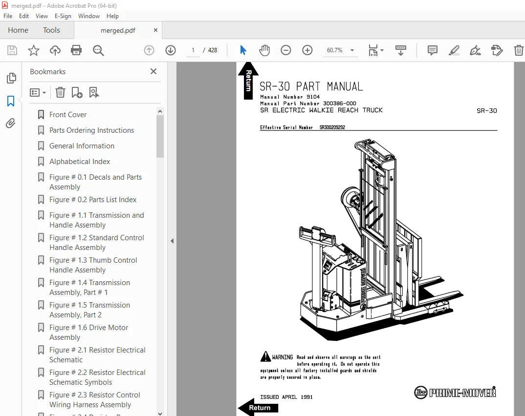
Manual Number 9104
Manual Part Number 300386-000
Effective Serial Number SR300209292
Description
BT Prime Mover SR-30 Electric Walkie Reach Truck Parts Manual – PDF DOWNLOAD
FILE DETAILS:
BT Prime Mover SR-30 Electric Walkie Reach Truck Parts Manual – PDF DOWNLOAD
Language : English
Pages : 428
Downloadable : Yes
File Type : PDF
IMAGES PREVIEW OF THE MANUAL:
TABLE OF CONTENTS:
BT Prime Mover SR-30 Electric Walkie Reach Truck Parts Manual – PDF DOWNLOAD
300386-000 1991_April
300386-001 1991_July
300386-002 1993_August
Manual Number 9104
Manual Part Number 300386-000
Effective Serial Number SR300209292
Front Cover 1
Parts Ordering Instructions 2
General Information 3
Alphabetical Index 4
Figure # 0 1 Decals and Parts Assembly 6
Figure # 0 2 Parts List Index 8
Figure # 1 1 Transmission and Handle Assembly 12
Figure # 1 2 Standard Control Handle Assembly 14
Figure # 1 3 Thumb Control Handle Assembly 16
Figure # 1 4 Transmission Assembly, Part # 1 18
Figure # 1 5 Transmission Assembly, Part 2 20
Figure # 1 6 Drive Motor Assembly 22
Figure # 2 1 Resistor Electrical Schematic 24
Figure # 2 2 Resistor Electrical Schematic Symbols 25
Figure # 2 3 Resistor Control Wiring Harness Assembly 26
Figure # 2 4 Resistor Power Component Wiring 28
Figure # 2 5 Resistor Control Panel Assembly 30
Figure # 2 7 Forward & Rearward Contactor Assembly 32
Figure # 2 8 Power Connector Assembly 34
Figure # 2 9 Drive Motor Assembly 36
Figure # 2 10 Pump Motor Assembly 38
Figure # 2 11 Warning Light Assembly 40
Figure # 3 1 Two Stage Hydraulic Schematic 42
Figure # 3 2 Two Stage Hydraulic Schematic Symbols 43
Figure # 3 3 Two Stage Hydraulic System – Part # 1 44
Figure # 3 4 Two Stage Hydraulic System – Part # 2 46
Figure # 3 5 Two Stage Lift Cylinder and Related Parts 48
Figure # 3 6 Two & Three Spool Control Valve Assembly 50
Figure # 3 7 Two Stage Mast Lift Pump and Motor Assembly 52
Figure # 3 8 Two Stage Lift Pump Assembly 54
Figure # 3 9 Two Stage Hydraulic Reservoir Assembly 56
Figure # 3 10 Two Stage Lift Cylinder Assembly 58
Figure # 3 11 Two Stage Mast Hose Reel and Related Parts 60
Figure # 3 12 Two Stage Mast Dual Elbow Swivel Assembly 62
Figure # 3 13 Two Stage Mast Gleason Hose Reel Assembly 64
Figure # 3 14 Two Stage Reach without Tilt Hose Assembly 66
Figure # 3 15 Two Stage Mast Reach Cylinder Assembly 68
Figure # 3 16 Two Stage Reach with Tilt Hose Assembly 70
Figure # 3 17 Two Stage Mast Tilt Cylinder Assembly 72
Figure # 3 18 Three Stage Mast Hydraulic Schematic 74
Figure # 3 19 Three Stage Mast Hydraulic Schematic Symbols 75
Figure # 3 20 Three Stage Hydraulic System – Part # 1 76
Figure # 3 21 Three Stage Hydraulic System – Part # 2 78
Figure # 3 22 Three Stage Lift Cylinders and Related Parts 80
Figure # 3 23 Two & Three Spool Control Valve Assembly 82
Figure # 3 24 Three Stage Mast Lift Pump and Motor Assembly 84
Figure # 3 25 Three Stage Lift Pump Assembly 86
Figure # 3 26 Three Stage Hydraulic Reservoir Assembly 88
Figure # 3 27 Three Stage Staging Cylinder Assembly 90
Figure # 3 28 Three Stage Freelift Cylinder Assembly 92
Figure # 3 29 Three Stage Mast Hose Reel and Related Parts 94
Figure # 3 30 Three Stage Mast Dual Elbow Swivel Assembly 96
Figure # 3 31 Three Stage Mast Gleason Hose Reel Assembly 98
Figure # 3 32 Three Stage Reach without Tilt Hose Assembly 100
Figure # 3 33 Three Stage Mast Reach Cylinder Assembly 102
Figure # 3 34 Three Stage Reach with Tilt Hose Assembly 104
Figure # 3 35 Three Stage Mast Tilt Cylinder Assembly 106
Figure # 4 1 Shielding Assembly 108
Figure # 4 2 Main Frame and Load Wheel Installation 110
Figure # 4 3 Caster Assembly 112
Figure # 4 4 Two & Three Spool Control Valve Mounting Assembly 114
Figure # 5 1 Two Stage Mast Installation 116
Figure # 5 2 Two Stage Mast Outer Column Assembly 118
Figure # 5 3 Two Stage Mast Inner Column Assembly 120
Figure # 5 4 Two Stage Mast Cylinder and Related Parts 122
Figure # 5 5 Two Stage Mast Lift Frame Assembly 124
Figure # 5 6 Three Stage Reach Assembly 126
Figure # 5 7 Two Stage Mast Reach Assembly 128
Figure # 5 8 Two Stage Fork Assembly 130
Figure # 5 9 Three Stage Mast Installation 132
Figure # 5 10 Three Stage Mast Outer Column Assembly 134
Figure # 5 11 Three Stage Mast Intermediate Column Assembly 136
Figure # 5 12 Three Stage Mast Inner Column Assembly 138
Figure # 5 13 Three Stage Mast Freelift Cylinder Installation 140
Figure # 5 14 Three Stage Mast Lift Frame Assembly 142
Figure # 5 15 Three Stage Reach Assembly 144
Figure # 5 16 Three Stage Mast Reach Assembly 146
Figure # 5 17 Three Stage Fork Assembly 148
Figure # 7 1 Special Tools and Lubrications 150
Front Cover 152
Parts Ordering Instructions 153
General Information 154
Alphabetical Index 155
Section 0 0 157
Figure # 0 1 157
Figure # 0 2 159
Section 1 0 161
Figure # 1 1 161
Figure # 1 2 163
Figure # 1 3 165
Figure # 1 4 167
Figure # 1 5 169
Section 2 0 171
Figure # 2 1 171
Figure # 2 2 172
Figure # 2 3 173
Figure # 2 4 174
Figure # 2 5 175
Figure # 2 6 177
Figure # 2 7 179
Figure # 2 8 181
Figure # 2 9 183
Figure # 2 10 185
Figure # 2 11 187
Figure # 2 12 189
Figure # 2 13 191
Section 3 0 193
Figure # 3 1 193
Figure # 3 2 194
Figure # 3 3 195
Figure # 3 4 197
Figure # 3 5 199
Figure # 3 6 201
Figure # 3 7 203
Figure # 3 8 205
Figure # 3 9 207
Figure # 3 10 209
Figure # 3 11 211
Figure # 3 12 213
Figure # 3 13 215
Figure # 3 14 217
Figure # 3 15 219
Figure # 3 16 221
Section 4 0 223
Figure # 4 1 223
Figure # 4 2 225
Figure # 4 3 227
Figure # 4 4 229
Section 5 0 231
Figure # 5 1 231
Figure # 5 2 233
Figure # 5 3 235
Figure # 5 4 237
Figure # 5 5 239
Figure # 5 6 241
Figure # 5 7 243
Figure # 5 8 245
Section 7 0 247
Figure # 7 1 247
Numerical Index 250
Front Cover 259
Parts Ordering Instructions 260
General Information 261
Alphabetical Index 262
Section 0 0 264
Figure # 0 1 Decals and Parts Assembly 264
Section 1 0 266
Figure # 1 1 Transmission and Handle Assembly 266
Figure # 1 2 Twist Grip Resistor/Transistor Control Handle Assembly 268
Figure # 1 3 Thumb Control Resistor/Transistor Control Handle Assembly 270
Figure # 1 4 Transmission Assembly, Part # 1 272
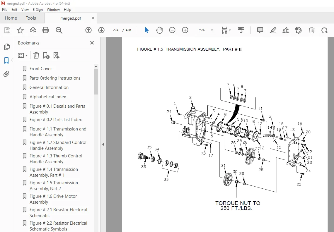
Figure # 1 5 Transmission Assembly, Part # 2 274
Figure # 1 6 Drive Motor Assembly 276
Section 2 0 278
Figure # 2 1 Resistor Electrical Schematic 278
Figure # 2 2 Resistor Electrical Schematic Symbols 279
Figure # 2 3 Resistor Control Wiring Harness Assembly 280
Figure # 2 4 Resistor Power Component Wiring 282
Figure # 2 5 Resistor Control Panel Assembly 284
Figure # 2 7 Forward & Rearward Contactor Assembly 286
Figure # 2 8 Power Connector Assembly 288
Figure # 2 9 Drive Motor Assembly 290
Figure # 2 10 Pump Motor Assembly 292
Figure # 2 11 Warning Light Assembly 294
Figure # 2 12 Transistor Electrical Schematic 296
Figure # 2 13 Transistor Electrical Schematic Symbols 297
Figure # 2 14 Transistor Control Wiring Harness Assembly 298
Figure # 2 15 Control Panel Assembly 300
Section 3 0 302
Figure # 3 1 Two Stage Hydraulic Schematic 302
Figure # 3 2 Two Stage Hydraulic Schematic Symbols 303
Figure # 3 3 Two Stage Hydraulic System – Part # 1 304
Figure # 3 4 Two Stage Hydraulic System – Part # 2 306
Figure # 3 5 Two Stage Lift Cylinder and Related Parts 308
Figure # 3 6 Two & Three Spool Control Valve Assembly 310
Figure # 3 7 Two Stage Mast Lift Pump and Motor Assembly 312
Figure # 3 8 Two Stage Lift Pump Assembly 314
Figure # 3 9 Two Stage Hydraulic Reservoir Assembly 316
Figure # 3 10 Two Stage Lift Cylinder Assembly 318
Figure # 3 11 Two Stage Mast Hose Reel and Related Parts 320
Figure # 3 12 Two Stage Mast Dual Elbow Swivel Assembly 322
Figure # 3 13 Two Stage Mast Gleason Hose Reel Assembly 324
Figure # 3 14 Two Stage Reach without Tilt Hose Assembly 326
Figure # 3 15 Two Stage Mast Reach Cylinder Assembly 328
Figure # 3 16 Two Stage Reach with Tilt Hose Assembly 330
Figure # 3 17 Two Stage Mast Tilt Cylinder Assembly 332
Figure # 3 18 Three Stage Mast Hydraulic Schematic 334
Figure # 3 19 Three Stage Mast Hydraulic Schematic Symbols 335
Figure # 3 20 Three Stage Hydraulic System – Part # 1 336
Figure # 3 21 Three Stage Hydraulic System – Part # 2 338
Figure # 3 22 Three Stage Lift Cylinders and Related Parts 340
Figure # 3 23 Two/Three Spool Control Valve Assembly 342
Figure # 3 24 Three Stage Mast Lift Pump and Motor Assembly 344
Figure # 3 25 Three Stage Lift Pump Assembly 346
Figure # 3 26 Three Stage Hydraulic Reservoir Assembly 348
Figure # 3 27 Three Stage Staging Cylinder Assembly 350
Figure # 3 28 Three Stage Freelift Cylinder Assembly 352
Figure # 3 29 Three Stage Mast Hose Reel and Related Parts 354
Figure # 3 30 Three Stage Mast Dual Elbow Swivel Assembly 356
Figure # 3 31 Three Stage Mast Gleason Hose Reel Assembly 358
Figure # 3 32 Three Stage Reach without Tilt Hose Assembly 360
Figure # 3 33 Three Stage Mast Reach Cylinder Assembly 362
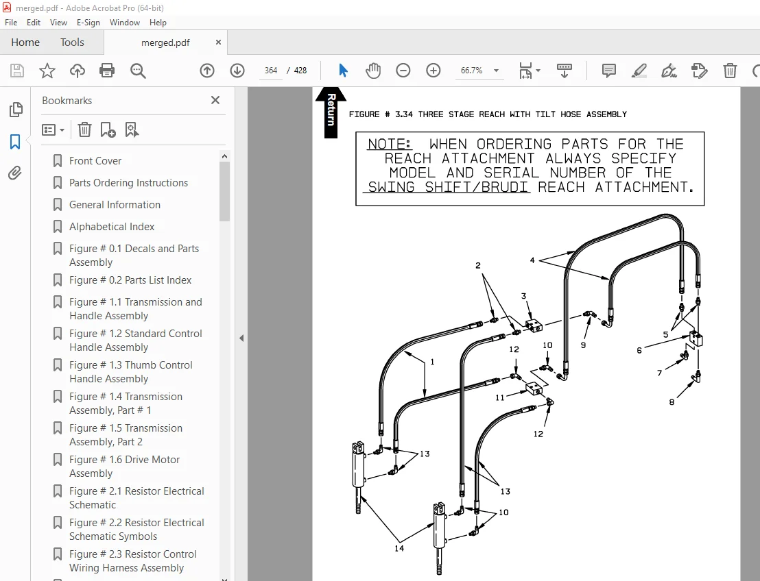
Figure # 3 34 Three Stage Reach with Tilt Hose Assembly 364
Figure # 3 35 Three Stage Mast Tilt Cylinder Assembly 366
Figure # 3 36 Three Stage Mast Auxiliary Hose Assembly 368
Section 4 0 370
Figure # 4 1 Shielding Assembly 370
Figure # 4 2 Main Frame and Load Wheel Installation 372
Figure # 4 3 Caster Assembly 374
Figure # 4 4 Two & Three Spool Control Valve Mounting Assembly 376
Section 5 0 378
Figure # 5 1 Two Stage Mast Installation 378
Figure # 5 2 Two Stage Mast Outer Column Assembly 380
Figure # 5 3 Two Stage Mast Inner Column Assembly 382
Figure # 5 4 Two Stage Mast Cylinder and Related Parts 384
Figure # 5 5 Two Stage Mast Lift Frame Assembly 386
Figure # 5 6 Three Stage Reach Assembly 388
Figure # 5 7 Two Stage Mast Reach Assembly 390
Figure # 5 8 Two Stage Fork Assembly 392
Figure # 5 9 Three Stage Mast Installation 394
Figure # 5 10 Three Stage Mast Outer Column Assembly 396
Figure # 5 11 Three Stage Mast Intermediate Column Assembly 398
Figure # 5 12 Three Stage Mast Inner Column Assembly 400
Figure # 5 13 Three Stage Mast Freelift Cylinder Installation 402
Figure # 5 14 Three Stage Mast Lift Frame Assembly 404
Figure # 5 15 Three Stage Reach Assembly 406
Figure # 5 16 Three Stage Mast Reach Assembly 408
Figure # 5 17 Three Stage Fork Assembly 410
Section 10 0 412
Figure # 10 1 Special Tools and Lubrications 412
Numerical Index 415
S.V 20/01/2025