BT Prime Mover RTX35/45, RTX30DR Electric Rider Truck Parts Manual PDF
$30.95
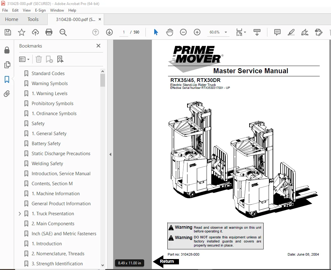
BT Prime Mover RTX35/45, RTX30DR Electric Rider Truck Parts Manual – PDF DOWNLOAD
Effective Serial Number RTX3530317001 – UP
Description
BT Prime Mover RTX35/45, RTX30DR Electric Rider Truck Parts Manual – PDF DOWNLOAD
FILE DETAILS:
BT Prime Mover RTX35/45, RTX30DR Electric Rider Truck Parts Manual – PDF DOWNLOAD
Language : English
Pages : 590
Downloadable : Yes
File Type : PDF
IMAGES PREVIEW OF THE MANUAL:
TABLE OF CONTENTS:
BT Prime Mover RTX35/45, RTX30DR Electric Rider Truck Parts Manual – PDF DOWNLOAD
Effective Serial Number RTX3530317001 – UP
Standard Codes 3
Warning Symbols 19
1 Warning Levels 19
Prohibitory Symbols 20
1 Ordinance Symbols 20
Safety 21
1 General Safety 21
Battery Safety 25
Static Discharge Precautions 29
Welding Safety 31
Introduction, Service Manual 33
Contents, Section M 35
1 Machine Information 35
General Product Information 37
1 Truck Presentation 37
1 1 Truck Side Views 37
1 2 Open Back Compartment 38
1 3 Intended Truck Application 38
1 4 Prohibited Truck Application 39
1 5 Truck Data 39
1 6 RTX35 Dimensions 40
1 7 RTX45 Dimensions 41
1 8 RTX30DR Dimensions 42
1 9 Data Plate 43
2 Main Components 45
Inch (SAE) and Metric Fasteners 49
1 Introduction 49
2 Nomenclature, Threads 50
3 Strength Identification 51
4 Truck Torque Specifications 57
5 Conversion of Metric and English Units 58
Technical Service Data 61
Ordering Spare Parts 65
Contents, Section P 67
1 Planned Maintenance 67
Introduction, Maintenance 69
1 Jacking Truck Off The Floor 70
1 1 Elevate Rear of Truck 70
1 1 Elevate Either Side of Truck 70
2 Lubricants 71
2 1 Standard 71
2 2 Cold Storage 71
2 3 Freezer Storage 73
Service Schedule 75
1 Planned Maintenance Schedule 75
2 Planned Maintenance Procedures 79
2 1 Services Performed Daily or Every 8 Operating Hours 79
2 1 1 Frame 79
2 1 2 Brake 79
2 1 3 Wheels/Tires 79
2 1 4 Functions/Operations 79
2 1 5 Battery Discharge Indicator with slow down 80
2 1 6 Hydraulic System 80
2 1 7 Frame/Sheet Metal 80
2 2 Services Performed Weekly or Every 30 Operating Hours 81
2 2 1 Battery 81
2 3 Services Performed Monthly or Every 120 Operating Hours 81
2 3 1 Inspection 81
2 3 2 Motors 81
2 3 3 Transmission 82
2 3 4 Brake 82
2 3 5 Battery 82
2 3 6 Electrical Connections 82
2 3 7 Contactor Tips (NOT Sealed) 82
2 3 8 Hydraulic Reservoir 82
2 3 9 Frame Lube 82
2 3 10 Pivot Points 83
2 3 11 Sideshifter 83
2 3 12 Reach 83
2 4 Services Performed Every Two Months or 240 Operating Hours 83
2 4 1 Wheels 83
2 4 2 Lifting Devices 83
2 5 Services Performed Every Three Months or 360 Operating Hours 84
2 5 1 Electrical Control System 84
2 5 2 Cylinders 84
2 5 3 Reach 84
2 6 Services Performed Semi-Annually or Every 720 Operating Hours 84
2 6 1 Inspection 84
2 6 2 Chassis 84
2 6 3 Transmission 84
2 6 4 Brake 84
2 6 5 Steering Wheel 85
2 6 6 Electrical Control System 85
2 6 7 Battery 85
2 6 8 Instrument Panel 85
2 6 9 Hydraulic System 85
2 6 10 Mast 85
2 6 11 Sideshifter 85
2 6 12 Lifting Device 85
2 6 13 Lift and Carriage Chains 85
2 7 Services Performed Annually or Every 1440 Operating Hours 86
2 7 1 Inspection 86
2 7 2 Transmission 86
2 7 3 Brakes 86
2 7 4 Battery 86
2 7 5 Hydraulic System 87
2 7 6 Sideshifter 87
Lubrication Chart 89
Oil and Grease Specifications 90
1 Lubricants 90
2 Grease Location Point 91
3 Chain Adjustment Points 92
Contents, Section S 93
1 Service Instructions 93
Chassis 95
1 Theory of Operation 96
2 Maintenance 96
3 Troubleshooting 96
4 Repair and Rebuild 96
4 1 Dash 96
4 2 Motor Compartment Door 97
4 3 Left Side Panel (Exterior) 98
4 4 Left Operator Compartment Panel 99
4 5 Main Electronic Card Panel 100
4 6 Floor Board 101
4 7 Clipboard 102
Battery Retainer Plates and Rollers 103
1 Theory of Operation 104
2 Maintenance 104
3 Troubleshooting 104
4 Repair and Rebuild 105
4 1 Battery Retainer Plates 105
4 2 Battery Rollers 105
Operator Controls 107
1 Theory of Operation 109
1 1 Controls and Instruments 110
2 Maintenance 117
3 Troubleshooting 117
4 Repair and Rebuild 117
4 1 Control Handle 117
4 2 Control Handle Shell 118
4 3 Throttle Potentiometer 121
4 4 Lift/Lower Pot Return Spring 123
4 5 Lift/lower Knob 123
4 6 Lift/lower Potentiometer 124
4 7 Tilt/Sideshift Switch Card 125
4 8 Reach/Retract Switches 127
Brake Pedal 129
Brake Pedal 130
1 Theory of Operation 131
2 Maintenance 131
2 1 Adjustment 131
3 Troubleshooting 131
4 Repair and Rebuild 131
4 1 Pedal Removal 131
4 2 Bearing Replacement 132
4 3 Pedal Reassembly 132
Internal Fittings 133
1 Theory of Operation 134
2 Maintenance 134
3 Troubleshooting 134
4 Repair and Rebuild 134
4 1 Operator Fan 134
Overhead Guard 137
1 Theory of Operation 138
2 Maintenance 138
3 Troubleshooting 138
4 Repair and Rebuild 138
Decals 139
1 Decal with Protective Sheet 139
2 Decal without Protective Sheet 139
Electric Motors 141
1 Theory of Operation 141
2 Maintenance 141
2 1 Commutator 143
2 2 Motor Brush Inspection 143
3 Troubleshooting 146
4 Repair 150
4 1 Brush Replacement 150
4 2 Pump Motor 155
4 3 Drive Motor 160
5 Rebuild 162
5 1 Pump Motor and Drive Motor Component Disassembly 162
5 1 Motor Inspection 164
5 1 1 Drive End Head 164
5 1 2 Commutator End Head 164
5 1 3 Bearings 164
5 1 4 Armature 164
5 1 5 Frame and Field Assembly 165
5 2 Assembly/Testing 166
5 2 1 Bearing Installation 166
5 2 2 Testing 167
Steering Motor 169
1 Theory of Operation 169
2 Maintenance 169
3 Troubleshooting 169
4 Repair and Rebuild 169
4 1 Steering Motor Gear Replacement 171
Fan Motor 173
1 Theory of Operation 173
2 Maintenance 173
3 Troubleshooting 173
4 Repair and Rebuild 173
4 1 Upper Electrical Compartment Fan 173
Transmission 175
1 Theory of Operation 176
2 Maintenance 176
2 1 Fluid Changing Procedure 176
2 2 Leakage 177
3 Troubleshooting 178
4 Repair and Rebuild 180
4 1 Transmission Disassembly 180
4 2 Axle Sealing Ring 196
Electromagnetic Brake 199
1 Theory of Operation 199
2 Maintenance 199
2 1 New Brake Air Gap Adjustment 199
2 2 Coil Check On Brake 200
2 3 Friction Plate 200
3 Troubleshooting 200
4 Repair and Rebuild 203
4 1 Brake Assembly 203
4 2 Brake, Armature and Magnetic Coil 205
Drive Wheel 207
1 Theory of Operation 207
2 Maintenance 207
3 Troubleshooting 208
4 Repair and Rebuild 208
Non-Braking Caster Assembly 211
1 Theory of Operation 213
2 Maintenance 213
2 1 Caster Spring Adjustment 213
2 1 Caster Stop Adjustment 213
3 Troubleshooting 214
4 Repair and Rebuild 215
4 1 Caster Pivot 215
4 2 Thrust Bearing 216
4 3 Caster Springs 217
Non-Braking Caster Wheels 219
1 Theory of Operation 219
2 Maintenance 219
2 1 Inspection 219
3 Troubleshooting 220
4 Repair and Rebuild 221
Braking Caster Assembly 223
1 Theory of Operation 225
2 Maintenance 225
2 1 Caster Brake Adjustment 225
3 Troubleshooting 228
4 Repair and Rebuild 228
Braking Caster Wheel Assembly 229
1 Theory of Operation 230
2 Maintenance 230
3 Troubleshooting 230
4 Repair and Rebuild 230
Load Wheels 233
1 Theory of Operation 235
2 Maintenance 235
3 Troubleshooting 235
4 Repair and Rebuild 235
4 1 Tandem Load Wheels 235
4 2 Single Load Wheels 237
Steering Wheel 239
1 Theory of Operation 240
2 Maintenance 240
3 Troubleshooting 240
4 Repair and Rebuild 241
4 1 Steering Wheel 241
4 2 Steer Tach 242
Steering Bearing 243
1 Theory of Operation 244
2 Maintenance 244
3 Troubleshooting 244
4 Repair and Rebuild 244
Electrical Functions 247
1 Theory of Operation 247
1 1 Start Up Battery Connected 248
1 2 Start Up E-Stop Released/Key ON 250
1 3 Steering Components 252
1 3 1 Steering System 252
1 3 2 Wheel Direction Sensors 256
1 4 Brake Release 259
1 5 Travel Request, Forks First 260
1 6 Travel Request, Forks Trailing 264
1 7 Plug Braking 268
1 7 1 Directional/Speed Control Handle Method 268
1 7 2 Brake Pedal Method 270
1 8 12-Volt Power Supply 272
1 9 7 35-Volt Power Supplies 273
1 9 1 7 35-Volt Power Supply Main Electronic Card 273
1 9 2 7 35-Volt Power Supply Control Handle Interface Card 274
1 10 Limit Switches 276
1 10 1 Truck Travel Speed Limiting 276
1 11 Mast Staging Speed Limiting 278
1 12 Height Indicator 280
1 13 Drive Motor Brush Wear Indicator Switches 283
1 14 Pump Motor Brush Wear Indicator Switches 284
1 15 Safety Check 285
1 16 Shunt Power Cable 287
2 Maintenance 288
2 1 Wiring 288
2 2 Definitions 289
2 3 Shorts to Frame Test 290
3 Troubleshooting 294
3 1 Warning/Caution Codes 296
3 1 1 Recalibration of Control Handle 299
3 2 Error codes 300
3 2 1 E102 Troubleshooting Procedures 301
3 2 1 POWER CIRCUIT CHECKS (LED #3) 302
3 2 2 REFERENCE CIRCUIT VALUE CHECKS (LED #4) 304
3 3 Parameters 305
3 4 Running time 305
3 5 Programming Parameters 305
3 6 Parameter 13 “Battery Type” Adjustment 307
3 6 1 24 Volt Unit Adjustment 310
3 6 2 36 Volt Unit Adjustment 312
Battery 315
1 Theory of Operation 315
2 Maintenance 315
2 1 Inspection and Care 315
2 2 Battery Exterior Cleaning 316
2 3 Charging 316
2 4 Storage 317
2 5 Battery History Record 317
3 Troubleshooting 318
4 Repair and Rebuild 319
Battery Connector 321
1 Theory of Operation 321
2 Maintenance 322
2 1 Inspection 322
3 Troubleshooting 322
4 Repair and Rebuild 323
Lights (Optional) 325
1 Theory of Operation 325
2 Maintenance 325
3 Troubleshooting 325
4 Repair and Rebuild 326
4 1 Overhead Guard Lights 326
4 2 Warning Lights 327
4 3 Working Lights 328
4 4 Travel/Back-up Alarm 329
Horn 331
1 Theory of Operation 331
2 Maintenance 331
3 Troubleshooting 331
4 Repair and Rebuild 332
Switches 333
1 Theory of Operation 333
2 Maintenance 334
2 1 Key Switch Inspection 334
2 2 Disconnect Switch Inspection 334
2 3 Mast Switch Inspection 334
2 4 Mast Switch Adjustment 335
3 Troubleshooting 335
4 Repair and Rebuild 336
4 1 Key Switch (S17) 336
4 2 Disconnect (Stop) Switch (S21) 337
4 3 Mast Switch (S31) 338
4 4 Lift Limit Override Switch (S33) 339
4 5 Light and Fan Switches (S96, S97 and S99) [Optional] 340
Control Cable and Harness 341
1 Theory of Operation 341
1 1 Fuses 341
1 2 Auxiliary Power Hook-up for On-board Terminal 342
2 Maintenance 342
2 1 Wiring Harness 342
2 2 Power Cables 343
3 Troubleshooting 343
4 Repair and Rebuild 343
Contactors 345
1 Theory of Operation 345
2 Maintenance 345
2 1 Contactor Tip Inspection 345
2 2 Testing Resistance 346
3 Troubleshooting 346
4 Repair and Rebuild 346
4 1 Main Contactor 347
4 2 Directional Contactors 349
4 3 Lift Bypass Contactor 351
Transistor Panel 353
1 Theory of Operation 353
1 1 Drive Motor Connections 353
1 1 1 Connections for controls 354
1 2 Pump Motor Connections 355
1 2 1 Connections for controls 356
2 Maintenance 357
2 1 Circuit Check 357
Main Electronic Card 359
1 Theory of Operation 359
1 1 Connectivity to Truck 359
1 2 Display 360
1 3 Time 361
2 Maintenance 367
2 1 RV2 Adjustment Procedure 367
2 2 Adjustment Procedures for Setting Brake Switch and Brake Transducer 368
3 Troubleshooting 369
4 Repair and Rebuild 369
Sensors and Switches 371
1 Theory of Operation 371
1 1 Staging Switch (S45) 371
1 2 Wheel Direction Sensor 371
1 3 Platform (Right Foot) Switch (S108) 371
1 4 Steer Stop Proximity Sensor A and Sensor B 372
1 5 Drive Motor Speed/Direction Sensors 372
2 Maintenance 372
2 1 Staging Switch (S45) Adjustment 372
2 2 Wheel Direction Sensor (S65) Adjustment 373
2 3 Steer Stop Proximity Sensor A (S66) and Sensor B (S67) Adjustment 374
3 Troubleshooting 375
4 Repair and Rebuild 375
4 1 Staging Switch (S45) 375
4 2 Wheel Direction Sensor (S65) 376
4 3 Platform (Right Foot) Switch (S108) 377
4 4 Steer Stop Proximity Sensor A (S66) and B (S67) 378
4 5 Drive Motor Speed (S65) and Direction (S125) Sensors 379
Hydraulic System 381
1 Theory of Operation 381
1 1 Control Handle Interface, Hydraulic Control Operation 382
1 2 Supply 386
1 3 Lifting 388
1 4 Lowering 390
1 5 Low Speed Extend 392
1 6 High Speed Extend 394
1 7 Low Speed Retract 396
1 8 High Speed Retract 398
1 9 Reach Impact (RTX35 Only) 400
1 10 Fork Tilt Up 402
1 11 Fork Tilt Down 404
1 12 Left Sideshift 406
1 13 Right Sideshift 408
2 Maintenance 412
2 1 Changing Hydraulic System Fluid 412
2 2 System Draining 413
2 3 System Refilling 414
2 4 Bleeding Hydraulic System 414
2 5 Setting Lift/Auxiliary Pressure Relief with a Rated Load 415
2 6 Hydraulic Lowering Rate Adjustment 416
2 7 Hydraulic Pump Testing 416
3 Troubleshooting 417
4 Repair and Rebuild 418
4 1 Control Valve 421
4 1 1 Proportional Pre-Pressure Reducing Valve, (Items 3, 4, 4a, 4b): 422
4 1 2 Valve Assembly SWR14 (Item 38) 423
4 1 3 Pressure Limiting Valve Assembly (Items 17 to 28) 423
4 1 4 Recondition Seal Kit for Lift/ Lower Valve (Items 3, 4a, 4b, 14, 18, 20, 31, 32, 33, and 34) 423
4 2 Hydraulic Reservoir Tank 425
4 3 Hydraulic Filter 428
4 4 Hydraulic Adapter 429
5 Hydraulic (Lift) Pump 431
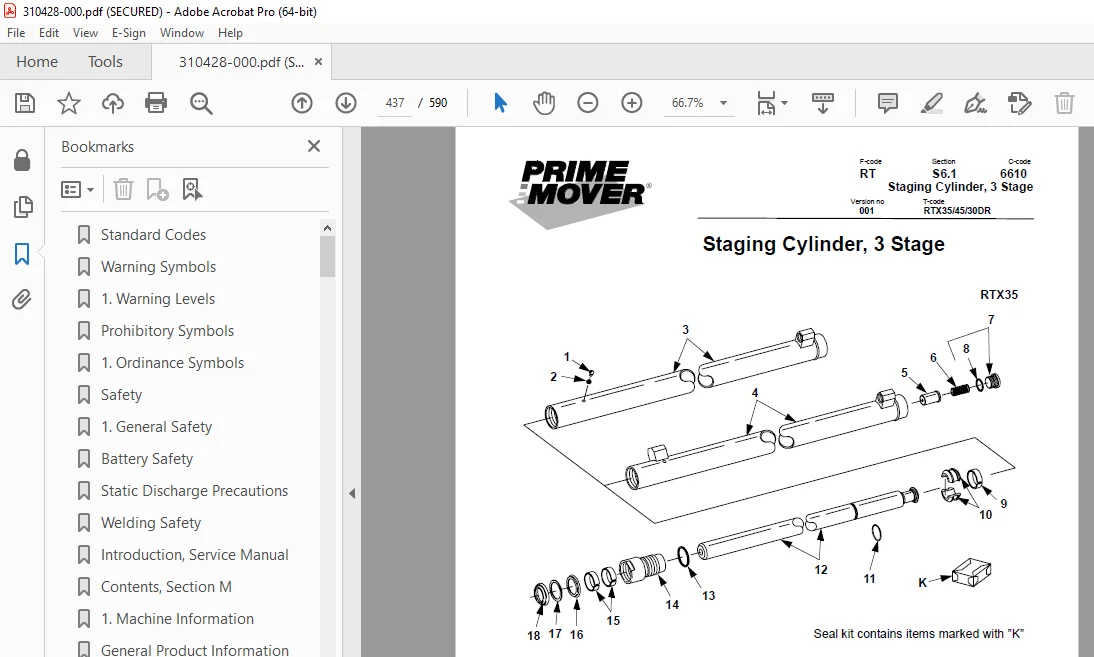
Staging Cylinder, 3 Stage 437
1 Theory of Operation 439
2 Maintenance 439
2 1 Inspection 439
3 Troubleshooting 440
4 Repair and Rebuild 440
Freelift Cylinder, 3 Stage 445
1 Theory of Operation 446
2 Maintenance 446
2 1 Inspection 446
3 Troubleshooting 447
4 Repair and Rebuild 447
Reach Cylinder 451
1 Theory of Operation 451
2 Maintenance 451
2 1 Inspection 451
3 Troubleshooting 452
4 Repair and Rebuild 452
4 1 Reach Cylinder (RTX35) 454
4 2 Reach Cylinder (RTX45) 458
4 3 Reach Cylinder (RTX30DR) 463
Tilt Cylinder 467
1 Theory of Operation 467
2 Maintenance 467
2 1 Inspection 467
3 Troubleshooting 468
4 Repair and Rebuild 468
4 1 Tilt Cylinder (RTX35) 470
4 2 Tilt Cylinder (RTX45) 474
4 3 Tilt Cylinder (RTX30DR) 479
Mast 483
1 Theory of Operation 483
2 Maintenance 483
2 1 Visual Inspection 483
2 2 Chain Inspection 483
2 3 Lubrication 488
2 4 Mast Adjustment 489
3 Troubleshooting 490
4 Repair and Rebuild 490
Lifting Gear (Crosshead) 503
1 Theory of Operation 505
2 Maintenance 505
3 Troubleshooting 505
4 Repair and Rebuild 505
Sideshifter 509
1 Theory of Operation 511
2 Maintenance 511
3 Troubleshooting 513
4 Repair and Rebuild 514
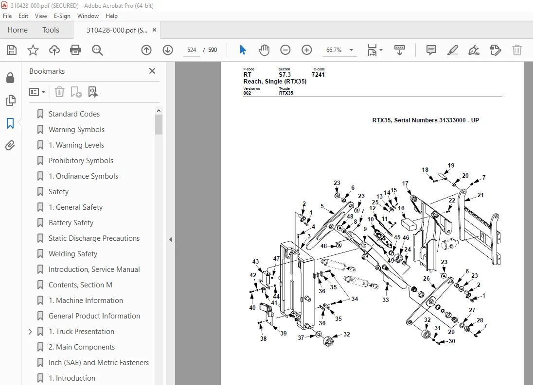
Reach, Single (RTX35) 519
1 Theory of Operation 519
2 Maintenance 519
2 1 Carriage/reach Retract Bumpers 519
2 2 Lower Bearings 519
2 3 Reach Adjustment 519
3 Troubleshooting 521
4 Repair and Rebuild 526
4 1 Reach 526
4 2 Front Frame 526
4 3 Outer Arm 527
4 4 Inner Arm 528
4 5 Rear Frame 529
4 6 Reach Cylinder 530
4 7 Carriage Roller Bearings 530
Reach, Single (RTX45) 531
1 Theory of Operation 531
2 Maintenance 531
2 1 Carriage/reach Retract Bumpers 531
2 2 Lower Bearings 531
3 Troubleshooting 531
4 Repair and Rebuild 534
4 1 Reach 534
4 2 Carriage Frame 534
4 3 Outer Arm 535
4 4 Inner Arm 536
4 5 Rear Frame 537
4 6 Reach Cylinder 538
4 7 Reach Carriage Wear Plate 539
4 8 Carriage Roller Bearings 540
Reach, Double (RTX30DR) 541
1 Theory of Operation 543
2 Maintenance 543
3 Troubleshooting 543
4 Repair 543
5 Rebuild 543
Forks 545
1 Theory of Operation 546
2 Maintenance 546
2 1 Inspection 546
3 Troubleshooting 546
4 Repair and Rebuild 547
Height Indicator 549
1 Theory of Operation 550
2 Maintenance 550
3 Troubleshooting 550
3 1 Error Code 13 550
4 Repair and Rebuild 552
4 1 Pulse Sensor (RTX35) 552
4 1 1 Cable (RTX35) 553
4 1 2 Pulley (RTX35) 553
4 2 Pulse Sensor (RTX45/30DR) 555
4 2 1 Cable (RTX45/30DR) 556
4 2 2 Pulley (RTX45/30DR) 556
Load Backrest 557
1 Theory of Operation 559
2 Maintenance 559
3 Troubleshooting 559
4 Repair and Rebuild 559
4 1 Load Backrest (RTX35/45) 559
4 2 Load Backrest (RTX30DR) 560
Appendix A 561
A 585
B 585
C 585
D 585
E 585
F 586
G 586
H 586
I 586
K 586
L 586
M 586
O 587
P 587
R 587
S 587
T 587
W 588
Back Cover 590
DESCRIPTION:
BT Prime Mover RTX35/45, RTX30DR Electric Rider Truck Parts Manual – PDF DOWNLOAD
Effective Serial Number RTX3530317001 – UP
S.V 10/01/2025