BT Prime Mover RS RR Series Truck RS20 RS30 RS40 RR20 RDR25 RR30 Operating & Parts Manual PDF
$27.95
BT Prime Mover RS RR Series Truck RS20 RS30 RS40 RR20 RDR25 RR30 Operating Maintenance & Parts Manual – PDF DOWNLOAD
Description
BT Prime Mover RS RR Series Truck RS20 RS30 RS40 RR20 RDR25 RR30 Operating Maintenance & Parts Manual – PDF DOWNLOAD
FILE DETAILS:
BT Prime Mover RS RR Series Truck RS20 RS30 RS40 RR20 RDR25 RR30 Operating Maintenance & Parts Manual – PDF DOWNLOAD
Language : English
Pages : 137
Downloadable : Yes
File Type : PDF
IMAGES PREVIEW OF THE MANUAL:
TABLE OF CONTENTS:
BT Prime Mover RS RR Series Truck RS20 RS30 RS40 RR20 RDR25 RR30 Operating Maintenance & Parts Manual – PDF DOWNLOAD
Front Cover 1
Warranty 2
New Owners 3
Contents 3
Preliminary Service 3
Operation Insutructions 3
Operating Rules and Instructions 4
Lubrication Chart 9
Maintenance Instructions 10
Service and Disassembly Instructions 13
Parts Ordering Instructions 25
RS20 Specifications 26
RS30 Specifications 27
RS40 Specifications 28
RR20 Specifications 29
RR30 Specifications 30
Figure # 1 Decal and Parts Assembly 32
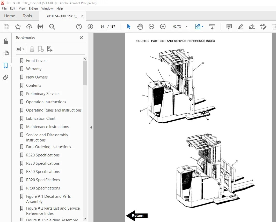
Figure # 2 Parts List and Service Reference Index 34
Figure # 3 Shielding Assembly 37
Figure # 4 Drive Mounting 39
Figure # 5 14:1 Transmission Assembly with MKU-4006 Drive Motor 41
Figure # 6 Motor Assembly 43
Figure # 7 Brake Linkage 44
Figure # 8 Slave Cylinder Assembly 46
Figure # 9 Master Cylinder Assembly 47
Figure # 10 Steering Linkage 48
Figure # 11 Steering Assembly 49
Figure # 12 Power Steering Gear Box 51
Figure # 13 Torque Generator 52
Figure # 14 Forward Gear Reduction Steering Gear Box, Reverse Chain Reduction Steering Gear Box 53
Figure # 15 GE Electrical Schematic – Model EV-1 54
Figure # 16 Electrical Schematic Symbols 55
Figure # 17 Wiring Harness Assembly 56
Figure # 18 Power Component Assembly 58
Figure # 19 SCR and Contactor Panel Assembly 59
Figure # 20 EV-1 SCR Control 60
Figure # 21 Transformer Assembly 61
Figure # 22 Rectifier Heat Sink Assembly 62
Figure # 23 GE Contactor Assembly 63
Figure # 24 Power Steering Contactor Assembly 64
Figure # 25 GE Contactor Assembly 65
Figure # 26 Warning Light Assembly 66
Figure # 27 Connector Assembly 67
Figure # 28 Handle Assembly 68
Figure # 29 Master Control Switch Assembly 69
Figure # 30 Master Control Switch Assembly 70
Figure # 31 Hydraulic Schematic 71
Figure # 32 Hydraulic Schematic Symbols 72
Figure # 33 Hydraulic Assembly (2 Stage) 73
Figure # 34 Hydraulic Assembly – Part # 1 74
Figure # 35 Tilt Cylinder Assembly and Related Parts 76
Figure # 36 Tilt Cylinder Assembly 77
Figure # 37 Lift Cylinder and Related Parts 78
Figure # 38 2″ Lift Cylinder Assembly 79
Figure # 39 2 1/2″ Lift Cylinder Assembly 81
Figure # 40 2 3/4″ Lift Cylinder Assembly 83
Figure # 41 Hydraulic Assembly (3 Stage) 85
Figure # 42 Hydraulic Assembly (3 Stage) Part # 2 86
Figure # 43 3 Stage Staging Cylinder Assembly 88
Figure # 44 Freelift Cylinder Assembly 89
Figure # 45 Hydraulic Assembly Part # 3 90
Figure # 46 Pump and Motor Assembly 91
Figure # 47 Motor Assembly 92
Figure # 48 Power Steering Pump Assembly 93
Figure # 50 Control Valve Assembly 96
Figure # 51 Control Valve Assembly 98
Figure # 52 Hydraulic Pump and Motor 99
Figure # 53 Pump Assembly 100
Figure # 54 Motor Assembly 101
Figure # 55 Motor Assembly 103
Figure # 56 Adjusting Linkage 104
Figure # 57 2 Stage Mast Assembly 105
Figure # 58 2 Stage Outer Column Assembly 107
Figure # 59 2 Stage Inner Column Assembly 108
Figure # 60 2 Stage Lift Cylinder and Related Parts 110
Figure # 61 RS-30/40 Lift Frame and Load Backrest 111
Figure # 62 RS-20 (Only) Lift Frame and Load Backrest 112
Figure # 63 3 Stage Mast Assembly 113
Figure # 64 Lift Frame Assembly 114
Figure # 65 Inner Column Assembly (3 Stage) 115
Figure # 66 Freelift Cylinder Assembly (3 Stage) 116
Figure # 67 Intermediate Column Assembly (3 Stage) 118
Figure # 68 Outer Column Assembly (3 Stage) 119
Figure # 69 Fork Assembly 120
Figure # 70 Auxiliary Hydraulic Valve Parts Breakdown 121
Figure # 71 Brudi Sideshifter 122
Figure # 72 Hydraulic Cylinder for Brudi Sideshifter 123
Figure # 73 Gleason Hose Reel Assembly (3 Stage Masts) 124
Figure # 74 Gleason Hose Reel 35 Series 125
Figure # 75 Dual Elbow Swivel Assembly 126
Figure # 76 Reach Attachment 127
Figure # 77 Reach Attachment 129
Figure # 78 Reach Attachment Hydraulic Assembly 131
Figure # 79 Reach Attachment Cylinder Assembly 132
Figure # 80 Load Wheel Assembly 134
Troubleshooting Hydraulic Gear Pump 135
Service Guide 136
S.V 20/01/2025