BT-Prime Mover RS-50B Electric Straddle Truck Parts Manual – PDF DOWNLOAD
$28.95
BT-Prime Mover RS-50B Electric Straddle Truck Parts Manual – PDF DOWNLOAD
Manual Number 9308
Manual Part no: 301042-002
Description
BT-Prime Mover RS-50B Electric Straddle Truck Parts Manual – PDF DOWNLOAD
FILE DETAILS:
BT-Prime Mover RS-50B Electric Straddle Truck Parts Manual – PDF DOWNLOAD
Language : English
Pages : 221
Downloadable : Yes
File Type : PDF
IMAGES PREVIEW OF THE MANUAL:
TABLE OF CONTENTS:
BT-Prime Mover RS-50B Electric Straddle Truck Parts Manual – PDF DOWNLOAD
Manual Number 9308
Manual Part no: 301042-002
A, B, C
Auxiliary Control Valve Assembly 3.4 3.5
Auxiliary Pump Assembly 3.6 3.9
Auxiliary Pump and Motor Assembly 3.5 3.7
Auxiliary Pump Motor Assembly, Ohio 2.22 2.39
Auxiliary Pump & Reservoir Assembly 3.3 3.3
Auxiliary Pump & Reservoir Assy. for 3 Function Control Handle 3.33 3.61
Auxiliary Control Assembly 4.3 4.5
Battery Lift Interrupt “E” EV-100LX SCR Electrical Schematic 7.1 7.1
Battery Lift Interrupt “E” EV-100LX SCR Electrical Schem. Symbols 7.2 7.2
Battery Lift Interrupt “EE” EV-100LX SCR Electrical Schematic 7.3 7.3
Battery Lift Interrupt “EE” EV-100LX SCR Electrical Schem. Symbols 7.4 7.4
Battery Lift Interrupt Installation 7.5 7.5
Brake Master Cylinder 3.28 3.53
D
Decals and Parts Assembly 0.1 0.1
Drive Motor Assembly, GE 2.21 2.37
Drive Motor Brake Assembly 1.2 1.3
Drive Motor Brake Cylinder 3.29 3.55
E
Emergency Disconnect Assembly 4.2 4.3
“E” EV-100LX SCR Electrical Schematic 2.1 2.1
“E” EV-100LX SCR Electrical Schematic Symbols 2.2 2.2
“E” EV-100LX TT SCR Electrical Schematic 2.24 2.43
“E” EV-100LX TT SCR Electrical Schematic Symbols 2.25 2.44
“EE” EV-100LX SCR Electrical Schematic 2.3 2.3
“EE” EV-100LX SCR Electrical Schematic Symbols 2.4 2.4
“EE” EV-100LX TT SCR Electrical Schematic 2.26 2.45
“EE” EV-100LX TT SCR Electrcical Schematic Symbols 2.27 2.46
EV-100LX Contactor Panel Assembly 2.14 2.23
EV-100LX Contactor Panel Assembly & Related Parts for “E” & “EE” 2.13 2.21
EV-100LX Dash Display Installation 2.28 2.47
EV-100LX Power Component Wiring 2.11 2.17
EV-100LX SCR 1A Contactor Assembly 2.16 2.27
EV-100LX SCR Auxiliary Pump Contactor Assembly 2.18 2.31
EV-100LX SCR Electrical Schematic – 3 Function Control Handle 2.29 2.49
EV-100LX SCR Electrical Schematic Symbols 2.30 2.50
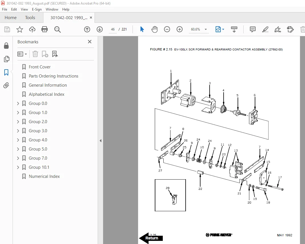
EV-100LX SCR Forward & Rearward Contactor Assembly 2.15 2.25
EV-100LX TT/TX SCR Control Panel Assembly 2.12 2.19
F, G, H
Five Inch High Articulating Load Wheel Assembly 4.10 4.19
Four Inch High Articulating Load Wheel Assembly 4.11 4.21
Hand Lift/Lower and Speed Control 4.4 4.7
Hand Lift/Lower and Speed Control for 3 Function Control 4.12 4.23
Hydraulic Reservoir Assembly 3.7 3.11
Hydraulic Schematic 3.1 3.1
Hydraulic Schematic Symbols 3.2 3.2
Hydraulic Schematic For 3 Function Control Handle 3.31 3.59
Hydraulic Schematic Symbols 3.32 3.60
ALPHABETICAL INDEX
MARCH 1994 4
NAME FIG.# PAGE #
I, J, K
Idler Wheel Assembly 4.7 4.13
Idler Wheel Brake Cylinder 3.30 3.57
Idler Wheel Installation 4.6 4.11
L
Lift Control Valve Assembly 3.21 3.39
Lift Pump Assembly, 24 VOLT 3.19 3.35
Lift Pump Assembly, 36 VOLT 3.20 3.37
Lift Pump Contactor Assembly 2.17 2.29
Lift Pump Motor Assembly 3.18 3.33
Lift Pump Motor Assembly, GE 2.20 2.35
Lift Pump and Reservoir Assembly 3.17 3.31
Limit Switch Wiring Assembly 2.7 2.9
M, N, O, P
Main Frame and Load Wheel Assembly 4.8 4.15
Power Connector Assembly 2.19 2.33
Q, R
Remote Lift/Lower Connector Assembly 6.7 6.11
Remote Lift/Lower EV-100 LX SCR Electrical Schematic 6.1 6.1
Remote Lift/Lower EV-100 LX SCR Electrical Schematic Symbols 6.2 6.2
Remote Lift/Lower Hydraulic Diagram 6.10 6.15
Remote Lift/Lower Hydraulic Schematic 6.8 6.13
Remote Lift/Lower Hydraulic Schematic Symbols 6.9 6.14
Remote Lfit/Lower Load Backrest Installation 6.13 6.21
Remote Lift/Lower Power Component Wiring 6.6 6.9
Remote Lift/Lower Reach and Platform Cable Assembly 6.5 6.7
Remote Lift/Lower Three Stage Mast Cable Assembly 6.4 6.5
Remote Lift/Lower Valve Assembly 6.12 6.19
Remote Lift/Lower Wiring Harness Assembly 6.3 6.3
S
Shielding Assembly 4.1 4.1
Sideshifter Cylinder With Tilt Assembly 3.15 3.27
Sideshifter Manifold Valve Assembly 3.16 3.29
Single Load Wheel Assembly 4.9 4.17
Special Tools and Lubrications 10.1 10.1
Steering Control Assembly 4.5 4.9
Steering Control Valve Assembly 3.8 3.13
Steering Control Valve and Hose Assembly 3.9 3.15
Steering Cylinder Assembly 3.10 3.17
ALPHABETICAL INDEX
5 MARCH 1994
NAME FIG.# PAGE #
T
Three Stage Cylinder and Reservoir Assembly 3.24 3.45
Three Stage Fork Assembly 5.15 5.29
Three Stage Freelift Cylinder Assembly 3.26 3.49
Three Stage Freelift Cylinder Installation 5.10 5.19
Three Stage Inner Column Assembly 5.9 5.17
Three Stage Intermediate Column Installation 5.11 5.21
Three Stage Lift Frame Assembly 5.13 5.25
Three Stage Mast Cable Assembly 2.9 2.13
Three Stage Mast Hydraulic Assembly 3.12 3.21
Three Stage Mast Hydraulic Assy. for 3 Function Control Handle 3.36 3.67
Three Stage Mast Installation 5.8 5.15
Three Stage Outer Column Assembly 5.12 5.23
Three Stage Sideshifter Assembly 5.14 5.27
Three Stage Staging Cylinder Assembly 3.25 3.47
Tilt Cylinder and Related Parts 3.13 3.23
Tilt With Sideshifter Cable Assembly 2.10 2.15
Transmission Assembly, Part #I 1.3 1.5
Transmission Assembly, Part #II 1.4 1.7
Transmission and Steering Installation 1.1 1.1
Two Stage Cylinder Assembly 3.23 3.43
Two Stage Cylinder Installation 5.4 5.7
Two Stage Cylinder and Reservoir Assembly 3.22 3.41
Two Stage Fork Assembly 5.7 5.13
Two Stage Inner Column Assembly 5.2 5.3
Two Stage Lift Frame Assembly 5.5 5.9
Two Stage Mast Cable Assembly 2.8 2.11
Two Stage Mast Hydraulic Assembly 3.11 3.19
Two Stage Mast Hydraulic Assy. for 3 Function Control Handle 3.35 3.65
Two Stage Mast Installation 5.1 5.1
Two Stage Outer Column Assembly 5.3 5.5
Two Stage Sideshifter Assembly 5.6 5.11
U, V
Valve Assembly 3.34 3.63
W, X, Y, Z
Warning Light Assembly 2.23 2.41
Wiring Assembly for Cold Storage 2.5 2.5
Wiring Harness 2.6 2.7
Wiring Harness Assembly for 3 Function Control Valve 2.31 2.51
S.V 11/01/2025