BT Prime-Mover RS-50B Electric Straddle Truck Parts Manual – PDF DOWNLOAD
$28.95
BT Prime-Mover RS-50B Electric Straddle Truck Parts Manual – PDF DOWNLOAD
Manual Number 9205
Manual Part Number 301042-001
Description
BT Prime-Mover RS-50B Electric Straddle Truck Parts Manual – PDF DOWNLOAD
FILE DETAILS:
BT Prime-Mover RS-50B Electric Straddle Truck Parts Manual – PDF DOWNLOAD
Language : English
Pages : 464
Downloadable : Yes
File Type : PDF
IMAGES PREVIEW OF THE MANUAL:
TABLE OF CONTENTS:
BT Prime-Mover RS-50B Electric Straddle Truck Parts Manual – PDF DOWNLOAD
Manual Number 9205
Manual Part Number 301042-001
A
Auxiliary control assembly 4.3 4.5
Auxiliary control valve assembly 3.4 3.5
Auxiliary pump and motor assembly, 24 volt 3.5 3.7
Auxiliary pump and motor assembly, 36 volt 3.5 3.7
Auxiliary pump and motor installation 4.7 4.13
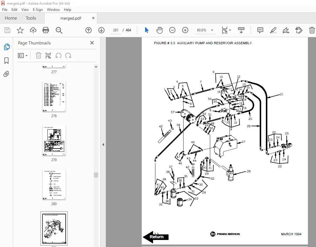
Auxiliary pump and reservoir assembly 3.3 3.3
Auxiliary pump assembly 3.6 3.9
Auxiliary pump motor assy., (24 Volt, OHIO, D-561371X8015A) 2.23 2.41
Auxiliary pump motor assy., (36 Volt, OHIO, D-561369X8005A) 2.23 2.41
B
Battery lift interrupt “E” EV-100LX SCR electrical schematic 7.1 7.1
Battery lift interrupt “E” EV-100LX SCR electrical schematic symbols 7.2 7.2
Battery lift interrupt “EE” EV-100LX SCR electrical schematic 7.3 7.3
Battery lift interrupt “EE” EV-100LX SCR electrical schematic symbols 7.4 7.4
Battery lift interrupt installation 7.5 7.5
Block manlift valve assembly, 24 VOLT 6.11 6.17
Block manlift valve assembly, 36 VOLT 6.11 6.17
C
Caster assembly 4.12 4.23
D
Decals and parts list assembly 0.1 0.1
Double reach cable assembly 2.11 2.17
Double reach diverter valve assembly 3.17 3.31
Double reach, reach cylinder assembly 3.18 3.33
Double reach, tilt cylinder assembly 3.19 3.35
Double reach with tilt and sideshifter 3.16 3.29
Drive motor assembly, (24 Volt, G.E., 5BT1326B235) 2.22 2.39
Drive motor assembly, (36 volt, G.E., 5BT1326B233) 2.22 2.39
Drive motor brake assembly 1.2 1.3
E
“E” EV-100LX SCR electrical schematic 2.1 2.1
“E” EV-100LX SCR electrical schematic symbols 2.2 2.2
“E” EV-100LX TT SCR electrical schematic 2.25 2.45
“E” EV-100LX TT SCR electrical schematic symbols 2.26 2.46
“EE” EV-100LX SCR electrical schematic 2.3 2.3
“EE” EV-100LX SCR electrical schematic symbols 2.4 2.4
“EE” EV-100LX TT SCR electrical schematic 2.27 2.47
“EE” EV-100LX TT SCR electrical schematic symbols 2.28 2.48
Emergency disconnect assembly 4.2 4.3
EV-100LX contactor panel assembly & related parts for “E”&”EE” 2.14 2.23
EV-100LX dash display installation 2.29 2.49
EV-100LX power component wiring 2.20 2.35
EV-100LX SCR 1A contactor assembly 2.17 2.29
EV-100LX SCR auxiliary pump contactor assembly 2.19 2.33
EV-100LX SCR contactor panel assembly, 24 volt 2.15 2.25
EV-100LX SCR contactor panel assembly, 36 volt 2.15 2.25
EV-100LX SCR forward & rearward contactor assembly 2.16 2.27
EV-100LX TT SCR control panel assembly 2.13 2.21
EV-100LX TX SCR control panel assembly 2.13 2.21
ALPHABETICAL INDEX
FEBRUARY 1992 5
NAME FIG.# PAGE #
F
4″ high articulating load wheel assembly 4.12 4.23
5″ high articulation load wheel assembly 4.11 4.21
Forward steering control assembly 4.5 4.9
G,H
Hand lift/lower and speed control 4.4 4.7
Hydraulic reservoir assembly 3.7 3.11
Hydraulic schematic 3.1 3.1
Hydraulic schematic symbols 3.2 3.2
I,J,K,L
Lift control valve assembly 3.24 3.45
Lift pump and reservoir assembly 3.20 3.37
Lift pump assembly, 24 VOLT 3.22 3.41
Lift pump assembly, 36 VOLT 3.22 3.41
Lift pump contactor assembly, (24 volt) 2.18 2.31
Lift pump contactor assembly, (36 volt) 2.18 2.31
Lift pump motor assembly 3.21 3.39
Lift Pump motor assembly, (24 volt, G.E., 5BT1324B54) 2.21 2.37
Lift Pump motor assembly, (36 volt, G.E., 5BT1326B234) 2.21 2.37
Limit switch wiring assembly 2.7 2.9
M
Main frame and load wheel assembly 4.8 4.15
Manlift connector assembly 6.7 6.11
Manlift EV-100LX SCR electrical schematic 6.1 6.1
Manlift EV-100LX SCR electrical schematic symbols 6.2 6.2
Manlift hydraulic diagram 6.10 6.15
Manlift hydraulic schematic 6.8 6.13
Manlift hydraulic schematic symbols 6.9 6.14
Manlift loadback rest installation 6.13 6.21
Manlift power component wiring 6.6 6.9
Manlift reach and platform cable assembly 6.5 6.7
Manlift three stage mast cable assembly 6.4 6.5
Manlift valve assembly, 24 VOLT 6.12 6.19
Manlift valve assembly, 36 VOLT 6.12 6.19
Manlift wiring harness assembly 6.3 6.3
N
Numerical index * 99.1
O,P
Parts list index 0.2 0.3
Power connector assembly, (GRAY) 2.20 2.35
Power connector assembly, (RED) 2.20 2.35
Q,R
Rearward steering control assembly 4.6 4.11
ALPHABETICAL INDEX
6 FEBRUARY 1992
NAME FIG.# PAGE #
S
Shielding assembly 4.1 4.1
Single load wheel assembly 4.9 4.17
Single reach cable assembly 2.10 2.15
Single reach cylinder assembly 3.13 3.23
Single reach cylinder hose installation 3.11 3.19
Single reach diverter valve assembly 3.12 3.21
Single tilt and sideshifter hose installation 3.14 3.25
Single tilt cylinder assembly, left 3.15 3.27
Single tilt cylinder assembly, right 3.15 3.27
Special tools and lubrications 10.1 10.1
T
Three stage cylinder and reservoir assembly 3.27 3.51
Three stage double reach assembly 5.18 5.35
Three stage double reach front frame assembly 5.19 5.37
Three stage fork assembly 5.21 5.39
Three stage freelift cylinder assembly 3.29 3.55
Three stage freelift cylinder installation 5.13 5.25
Three stage inner column assembly 5.12 5.23
Three stage intermediate column assembly 5.14 5.27
Three stage mast cable assembly 2.9 2.13
Three stage mast hydraulic assembly 3.10 3.17
Three stage mast installation 5.11 5.21
Three stage outer column assembly 5.15 5.29
Three stage sideshifter assembly 5.20 5.39
Three stage single reach assembly 5.16 5.31
Three stage single reach front frame assembly 5.17 5.33
Three stage staging cylinder assembly 3.28 3.53
Torque generator assembly 3.8 3.13
Transmission and drive motor installation 1.1 1.1
Transmission assembly, PART I 1.2 1.3
Transmission assembly, PART II 1.3 1.5
Two stage cylinder and reservoir assembly 3.25 3.47
Two stage cylinder assembly 3.26 3.49
Two stage cylinder installation 5.4 5.7
Two stage double reach assembly 5.7 5.13
Two stage double reach front frame assembly 5.8 5.15
Two stage inner column assembly 5.2 5.3
Two stage mast cable assembly 2.8 2.11
Two stage mast fork assembly 5.10 5.19
Two stage mast hydraulic assembly 3.9 3.15
Two stage mast installation 5.1 5.1
Two stage outer column assembly 5.3 5.5
Two stage sideshifter assembly 5.9 5.17
Two stage single reach assembly 5.5 5.9
Two stage single reach front frame assembly 5.6 5.11
ALPHABETICAL INDEX
FEBRUARY 1992 7
NAME FIG.# PAGE #
U,V,W
Warning light assembly, 24 volt 2.24 2.43
Warning light assembly, 36 volt 2.24 2.43
Wiring assembly for cold storage 2.5 2.5
Wiring harness assembly 2.6 2.7
X,Y,Z
DESCRIPTION:
BT Prime-Mover RS-50B Electric Straddle Truck Parts Manual – PDF DOWNLOAD
Manual Number 9205
Manual Part Number 301042-001
PARTS ORDERING INSTRUCTIONS:
HOW TO ORDER:
- When you order, supply the part number, quantity, model and serial numbers of your machine. Supplying this information will assure prompt, efficient handling of your order. The pictorial reference number is not needed and including it can only add confusion.
- Since your dealer carries many parts in stock and maintains up-to-date prices on all parts, he will be able to process your order immediately. If, for some reason, the part is not in stock, he will order it from the factory. In either event, he maintains a current file of Service Referneces, which give all available parts ordering or technical information.
- All prices are FOB factory in Muscatine, Iowa. Shipping charges are added to the price of the part shipped from the factory.
WHERE TO ORDER:
Always order parts from the dealer who sold you your BT PRIME-MOVER. If It is necessary for the dealer to order parts from the factory, he is able to get prompt service for you. Parts are shipped in accord- ance with shipping instructions given on the order.
S.V 04/02/2025