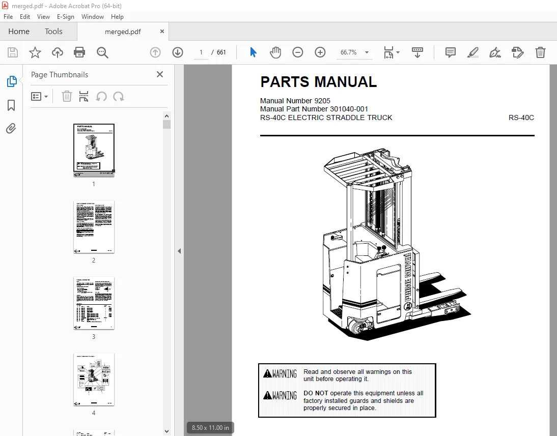
BT Prime Mover RS-40C Electric Straddle Truck Parts Manual – PDF DOWNLOAD
$31.95
BT Prime Mover RS-40C Electric Straddle Truck Parts Manual – PDF DOWNLOAD
Description
BT Prime Mover RS-40C Electric Straddle Truck Parts Manual – PDF DOWNLOAD
FILE DETAILS:
BT Prime Mover RS-40C Electric Straddle Truck Parts Manual – PDF DOWNLOAD
Language : English
Pages : 661
Downloadable : Yes
File Type : PDF
IMAGES PREVIEW OF THE MANUAL:
TABLE OF CONTENTS:
BT Prime Mover RS-40C Electric Straddle Truck Parts Manual – PDF DOWNLOAD
Front Cover 1
Parts Ordering Instructions 2
General Information 3
Figure # 0 1 Decals and Parts Assembly 4
Figure # 0 2 Parts List Index 6
Figure # 1 1 Transmission and Drive Motor Installation 10
Figure # 1 2 Drive Motor and Brake Assembly 12
Figure # 1 3 Transmission Assembly 14
Figure # 1 4 Transmission Assembly 16
Figure # 2 1 “E” EV-100LX SCR Electrical Schematic 18
Figure # 2 2 “E” EV-100LX SCR Electrical Schematic Symbols 19
Figure # 2 3 “EE” EV-100LX SCR Electrical Schematic 20
Figure # 2 4 “EE” EV-100LX SCR Electrical Schematic Symbols 21
Figure # 2 5 Wiring Assembly for Cold Storage 22
Figure # 2 6 Wiring Harness Assembly 24
Figure # 2 7 Limit Switch Wiring Assembly 26
Figure # 2 8 Two Stage Mast Cable Assembly 28
Figure # 2 9 Three Stage Mast Cable Assembly 30
Figure # 2 10 Tilt with Sideshifter Cable Assembly 32
Figure # 2 11 EV-100LX Power Component Wiring 34
Figure # 2 12 EV-100LX TX & TT SCR Control Panel Assembly 36
Figure # 2 13 EV-100LX Contactor Panel Assembly & Related Parts for “E” and “EE” 38
Figure # 2 14 EV-100LX Contactor Panel Assembly 40
Figure # 2 15 EV-100LX SCR Forward & Rearward Contactor Assembly 42
Figure # 2 16 EV-100LX SCR 1A Contactor Assembly 44
Figure # 2 17 Lift Pump Contactor Assembly 46
Figure # 2 18 EV-100LX SCR Auxiliary Pump Contactor Assembly 48
Figure # 2 19 Power Connector Assembly 50
Figure # 2 20 Lift Pump Motor Assembly 52
Figure # 2 21 Drive Motor Assembly 54
Figure # 2 22 Auxiliary Pump Motor Assembly 56
Figure # 2 23 Warning Light Assembly 58
Figure # 2 24 “E” EV-100LX TT SCR Electrical Schematic 60
Figure # 2 25 “E” EV-100LX TT SCR Electrical Schematic Symbols 61
Figure # 2 26 “EE” EV-100LX TT SCR Electrical Schematic 62
Figure # 2 27 “EE” EV-100LX TT SCR Electrical Schematic Symbols 63
Figure # 2 28 EV-100LX Dash Display Installation 64
Figure # 3 1 Hydraulic Schematic 66
Figure # 3 2 Hydraulic Schematic Symbols 67
Figure # 3 3 Auxiliary Pump and Reservoir Assembly 68
Figure # 3 4 Auxiliary Control Valve Assembly 70
Figure # 3 5 Auxiliary Pump and Motor Assembly 72
Figure # 3 6 Auxiliary Pump Assembly 74
Figure # 3 7 Hydraulic Reservoir Assembly 76
Figure # 3 8 Torque Generator Assembly 78
Figure # 3 9 Two Stage Mast Hydraulic Assembly 80
Figure # 3 10 Three Stage Mast Hydraulic Assembly 82
Figure # 3 11 Tilt Cylinder and Related Parts 84
Figure # 3 12 Tilt Cylinder Assembly 86
Figure # 3 13 Sideshifter Cylinder with Tilt Assembly 88
Figure # 3 14 Sideshifter Manifold Valve Assembly 90
Figure # 3 15 Lift Pump and Reservoir Assembly 92
Figure # 3 16 Lift Pump Motor Assembly 94
Figure # 3 17 Lift Pump Assembly, 24 Volt 96
Figure # 3 18 Lift Pump Assembly, 36 Volt 98
Figure # 3 19 Lift Control Valve Assembly 100
Figure # 3 20 Two Stage Cylinder and Reservoir Assembly 102
Figure # 3 21 Two Stage Cylinder Assembly 104
Figure # 3 22 Three Stage Cylinder and Reservoir Assembly 106
Figure # 3 23 Three Stage Staging Cylinder Assembly 108
Figure # 3 24 Three Stage Freelift Cylinder Assembly 110
Figure # 4 1 Shielding Assembly 112
Figure # 4 2 Emergency Disconnect Assembly 114
Figure # 4 3 Auxiliary Control Assembly 116
Figure # 4 4 Hand Lift/Lower and Speed Control 118
Figure # 4 5 Forward Steering Control Assembly 120
Figure # 4 6 Rearward Steering Control Assembly 122
Figure # 4 7 Auxiliary Pump and Motor Installation 124
Figure # 4 8 Main Frame and Load Wheel Assembly 126
Figure # 4 9 Single Load Wheel Assembly 128
Figure # 4 10 5″ High Articulating Load Wheel Assembly 130
Figure # 4 11 4″ High Articulating Load Wheel Assembly 132
Figure # 4 12 Caster Assembly 134
Figure # 5 1 Two Stage Mast Installation 136
Figure # 5 2 Two Stage Inner Column Assembly 138
Figure # 5 3 Two Stage Outer Column Assembly 140
Figure # 5 4 Two Stage Cylinder Installation 142
Figure # 5 5 Two Stage Lift Frame Assembly 144
Figure # 5 6 Two Stage Sideshifter Assembly 146
Figure # 5 7 Two Stage Fork Assembly 148
Figure # 5 8 Three Stage Mast Installation 150
Figure # 5 9 Three Stage Inner Column Assembly 152
Figure # 5 10 Three Stage Freelift Cylinder Installation 154
Figure # 5 11 Three Stage Intermediate Column Assembly 156
Figure # 5 12 Three Stage Outer Column Assembly 158
Figure # 5 13 Three Stage Lift Frame Assembly 160
Figure # 5 14 Three Stage Sideshifter Assembly 162
Figure # 5 15 Three Stage Fork Assembly 164
Figure # 7 1 Battery Lift Interrupt “E” EV-100LX SCR Electrical Schematic 166
Figure # 7 2 Battery Lift Interrupt “E” EV-100LX SCR Electrical Schematic Symbols 167
Figure # 7 3 Battery Lift Interrupt “EE” EV-100LX SCR Electrical Schematic 168
Figure # 7 4 Battery Lift Interrupt “EE” EV-100LX SCR Electrical Schematic Symbols 169
Figure # 7 5 Battery Lift Interrupt Installation 170
Figure # 10 1 Special Tools and Lubrications 172
Numerical Index 175
Front Cover 190
Parts Ordering Instructions 191
Field Modifications 191
General Information 192
Alphabetical Index 193
Figure # 0 1 Decals and Parts Assembly 197
Figure # 1 1 Transmission and Drive Motor Installation 199
Figure # 1 2 Drive Motor and Brake Assembly 201
Figure # 1 3 Transmission Assembly Part #1 203
Figure # 1 4 Transmission Assembly Part #2 205
Figure # 2 1 “E” EV-100LX SCR Electrical Schematic 207
Figure # 2 2 “E” EV-100LX SCR Electrical Schematic Symbols 208
Figure # 2 3 “EE” EV-100LX SCR Electrical Schematic 209
Figure # 2 4 “EE” EV-100LX SCR Electrical Schematic Symbols 210
Figure # 2 5 Wiring Assembly for Cold Storage 211
Figure # 2 6 Wiring Harness Assembly 213
Figure # 2 7 Limit Switch Wiring Assembly 215
Figure # 2 8 Two Stage Mast Cable Assembly 217
Figure # 2 9 Three Stage Mast Cable Assembly 219
Figure # 2 10 Tilt with Sideshifter Cable Assembly 221
Figure # 2 11 EV-100LX Power Component Wiring 223
Figure # 2 12 EV-100LX TX & TT SCR Control Panel Assembly 225
Figure # 2 13 EV-100LX Contactor Panel Assembly & Related Parts for “E” and “EE” 227
Figure # 2 14 EV-100LX Contactor Panel Assembly 229
Figure # 2 15 EV-100LX SCR Forward & Rearward Contactor Assembly 231
Figure # 2 16 EV-100LX SCR 1A Contactor Assembly 233
Figure # 2 17 Lift Pump Contactor Assembly 235
Figure # 2 18 EV-100LX SCR Auxiliary Pump Contactor Assembly 237
Figure # 2 19 Power Connector Assembly 239
Figure # 2 20 Lift Pump Motor Assembly 241
Figure # 2 21 Drive Motor Assembly 243
Figure # 2 22 Auxiliary Pump Motor Assembly 245
Figure # 2 23 Warning Light Assembly 247
Figure # 2 24 “E” EV-100LX TT SCR Electrical Schematic 249
Figure # 2 25 “E” EV-100LX TT SCR Electrical Schematic Symbols 250
Figure # 2 26 “EE” EV-100LX TT SCR Electrical Schematic 251
Figure # 2 27 “EE” EV-100LX TT SCR Electrical Schematic Symbols 252
Figure # 2 28 EV-100LX Dash Display Installation 253
Figure # 2 29 EV-100LX SCR Electrical Schematic – 3 Function Control Handle 255
Figure # 2 30 EV-100LX SCR Electrical Schematic Symbols 256
Figure # 2 31 Wiring Harness Assembly for 3 Function Control Valve 257
Figure # 3 1 Hydraulic Schematic 259
Figure # 3 2 Hydraulic Schematic Symbols 260
Figure # 3 3 Auxiliary Pump and Reservoir Assembly 261
Figure # 3 4 Auxiliary Control Valve Assembly 263
Figure # 3 5 Auxiliary Pump and Motor Assembly 265
Figure # 3 6 Auxiliary Pump Assembly 267
Figure # 3 7 Hydraulic Reservoir Assembly 269
Figure # 3 8 Torque Generator Assembly 271
Figure # 3 9 Two Stage Mast Hydraulic Assembly 273
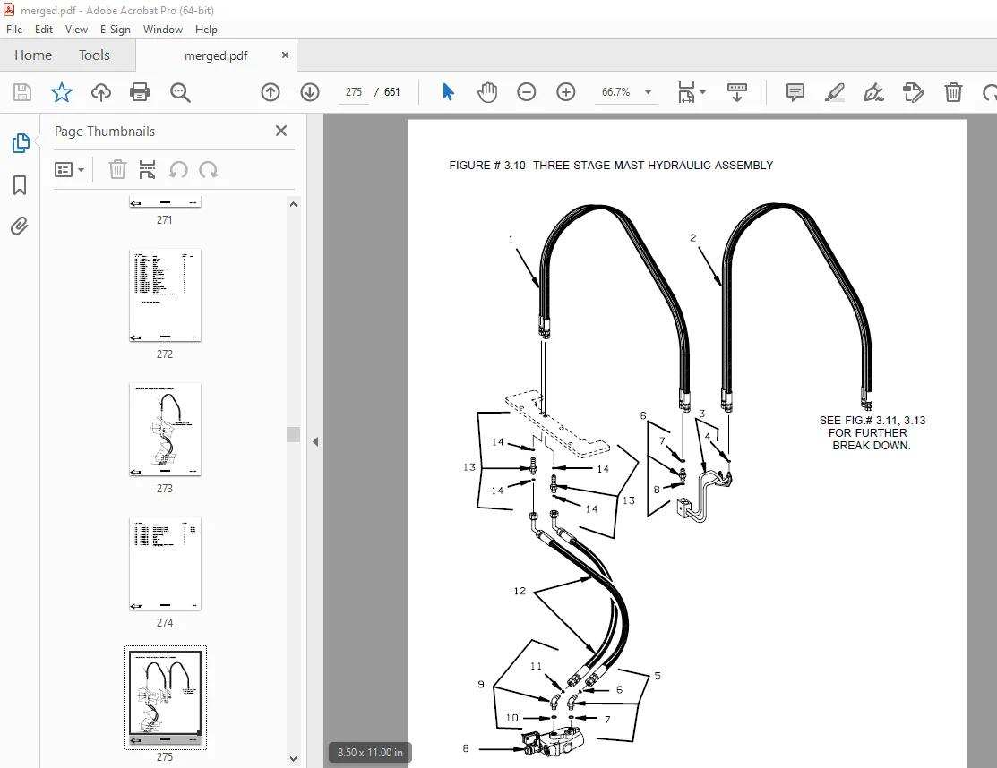
Figure # 3 10 Three Stage Mast Hydraulic Assembly 275
Figure # 3 11 Tilt Cylinder and Related Parts 277
Figure # 3 12 Tilt Cylinder Assembly 279
Figure # 3 13 Sideshifter Cylinder with Tilt Assembly 281
Figure # 3 14 Sideshifter Manifold Valve Assembly 283
Figure # 3 15 Lift Pump and Reservoir Assembly 285
Figure # 3 16 Lift Pump Motor Assembly 287
Figure # 3 17 Lift Pump Assembly, 24 Volt 289
Figure # 3 18 Lift Pump Assembly, 36 Volt 291
Figure # 3 19 Lift Control Valve Assembly 293
Figure # 3 20 Two Stage Cylinder and Reservoir Assembly 295
Figure # 3 21 Two Stage Cylinder Assembly 297
Figure # 3 22 Three Stage Cylinder and Reservoir Assembly 299
Figure # 3 23 Three Stage Staging Cylinder Assembly 301
Figure # 3 24 Three Stage Freelift Cylinder Assembly 303
Figure # 3 25 Hydraulic Schematic for 3 Function Control Handle 305
Figure # 3 26 Hydraulic Schematic Symbols 306
Figure # 3 27 Auxiliary Pump & Reservoir Assembly for 3 Function Control Handle 307
Figure # 3 28 Valve Assembly 309
Figure # 3 29 Two Stage Mast Hydraulic Assembly 311
Figure # 3 30 Three Stage Mast Hydraulic Assembly 313
Figure # 4 1 Shielding Assembly 315
Figure # 4 2 Emergency Disconnect Assembly 317
Figure # 4 3 Auxiliary Control Assembly 319
Figure # 4 4 Hand Lift/Lower and Speed Control 321
Figure # 4 5 Forward Steering Control Assembly 323
Figure # 4 6 Rearward Steering Control Assembly 325
Figure # 4 7 Auxiliary Pump and Motor Installation 327
Figure # 4 8 Main Frame and Load Wheel Assembly 329
Figure # 4 9 Single Load Wheel Assembly 331
Figure # 4 10 5″ High Articulating Load Wheel Assembly 333
Figure # 4 11 4″ High Articulating Load Wheel Assembly 335
Figure # 4 12 Caster Assembly 337
Figure # 4 13 Hand Lift/Lower and Speed Control for 3 Function Control 339
Figure # 5 1 Two Stage Mast Installation 341
Figure # 5 2 Two Stage Inner Column Assembly 343
Figure # 5 3 Two Stage Outer Column Assembly 345
Figure # 5 4 Two Stage Cylinder Installation 347
Figure # 5 5 Two Stage Lift Frame Assembly 349
Figure # 5 6 Two Stage Sideshifter Assembly 351
Figure # 5 7 Two Stage Fork Assembly 353
Figure # 5 8 Three Stage Mast Installation 355
Figure # 5 9 Three Stage Inner Column Assembly 357
Figure # 5 10 Three Stage Freelift Cylinder Installation 359
Figure # 5 11 Three Stage Intermediate Column Assembly 361
Figure # 5 12 Three Stage Outer Column Assembly 363
Figure # 5 13 Three Stage Lift Frame Assembly 365
Figure # 5 14 Three Stage Sideshifter Assembly 367
Figure # 5 15 Three Stage Fork Assembly 369
Figure # 6 1 Manlift EV-100 LX SCR Electrical Schematic 371
Figure # 6 2 Manlift EV-100 LX SCR Electrical Schematic Symbols 372
Figure # 6 3 Manlift Wiring Harness Assembly 373
Figure # 6 4 Manlift Three Stage Mast Cable Assembly 375
Figure # 6 5 Manlift Reach and Platform Cable Assembly 377
Figure # 6 6 Manlift Power Component Wiring 379
Figure # 6 7 Manlift Connector Assembly 381
Figure # 6 8 Manlift Hydraulic Schematic 383
Figure # 6 9 Manlift Hydraulic Schematic Symbols 384
Figure # 6 10 Manlift Hydraulic Diagram 385
Figure # 6 11 Blocking Manlift Valve Assembly 387
Figure # 6 12 Manlift Valve Assembly 389
Figure # 6 13 Manlift Load Backrest Installation 391
Figure # 7 1 Battery Lift Interrupt “E” EV-100LX SCR Electrical Schematic 393
Figure # 7 2 Battery Lift Interrupt “E” EV-100LX SCR Electrical Schematic Symbols 394
Figure # 7 3 Battery Lift Interrupt “EE” EV-100LX SCR Electrical Schematic 395
Figure # 7 4 Battery Lift Interrupt “EE” EV-100LX SCR Electrical Schematic Symbols 396
Figure # 7 5 Battery Lift Interrupt Installation 397
Figure # 10 1 Special Tools and Lubrications 399
Numerical Index 402
Front Cover 417
Parts Ordering Instructions 418
Field Modifications 418
General Information 419
Alphabetical Index 420
Figure # 0 1 Decals and Parts Assembly 424
Figure # 1 1 Transmission and Drive Motor Installation 426
Figure # 1 2 Drive Motor and Brake Assembly 428
Figure # 1 3 Transmission Assembly Part #1 430
Figure # 1 4 Transmission Assembly Part #2 432
Figure # 2 1 “E” EV-100LX SCR Electrical Schematic 434
Figure # 2 2 “E” EV-100LX SCR Electrical Schematic Symbols 435
Figure # 2 3 “EE” EV-100LX SCR Electrical Schematic 436
Figure # 2 4 “EE” EV-100LX SCR Electrical Schematic Symbols 437
Figure # 2 5 Wiring Assembly for Cold Storage 438
Figure # 2 6 Wiring Harness Assembly 440
Figure # 2 7 Limit Switch Wiring Assembly 442
Figure # 2 8 Two Stage Mast Cable Assembly 444
Figure # 2 9 Three Stage Mast Cable Assembly 446
Figure # 2 10 Tilt with Sideshifter Cable Assembly 448
Figure # 2 11 EV-100LX Power Component Wiring 450
Figure # 2 12 EV-100LX TX & TT SCR Control Panel Assembly 452
Figure # 2 13 EV-100LX Contactor Panel Assembly & Related Parts for “E” and “EE” 454
Figure # 2 14 EV-100LX Contactor Panel Assembly 456
Figure # 2 15 EV-100LX SCR Forward & Rearward Contactor Assembly 458
Figure # 2 16 EV-100LX SCR 1A Contactor Assembly 460
Figure # 2 17 Lift Pump Contactor Assembly 462
Figure # 2 18 EV-100LX SCR Auxiliary Pump Contactor Assembly 464
Figure # 2 19 Power Connector Assembly 466
Figure # 2 20 Lift Pump Motor Assembly 468
Figure # 2 20A Lift Pump Motor Assembly, 36 Volt G E 470
Figure # 2 21 Drive Motor Assembly 472
Figure # 2 22 Auxiliary Pump Motor Assembly 474
Figure # 2 23 Warning Light Assembly 476
Figure # 2 24 “E” EV-100LX TT SCR Electrical Schematic 478
Figure # 2 25 “E” EV-100LX TT SCR Electrical Schematic Symbols 479
Figure # 2 26 “EE” EV-100LX TT SCR Electrical Schematic 480
Figure # 2 27 “EE” EV-100LX TT SCR Electrical Schematic Symbols 481
Figure # 2 28 EV-100LX Dash Display Installation 482
Figure # 2 29 EV-100LX SCR Electrical Schematic – 3 Function Control Handle 484
Figure # 2 30 EV-100LX SCR Electrical Schematic Symbols 485
Figure # 2 29A EV-100LX SCR Electrical Schematic – 3 Function Control Handle 486
Figure # 2 30A EV-100LX SCR Electrical Schematic Symbols 487
Figure # 2 31 Wiring Harness Assembly for 3 Function Control Valve 488
Figure # 3 1 Hydraulic Schematic 490
Figure # 3 2 Hydraulic Schematic Symbols 491
Figure # 3 3 Auxiliary Pump and Reservoir Assembly 492
Figure # 3 4 Auxiliary Control Valve Assembly 494
Figure # 3 5 Auxiliary Pump and Motor Assembly 496
Figure # 3 6 Auxiliary Pump Assembly 498
Figure # 3 7 Hydraulic Reservoir Assembly 500
Figure # 3 8 Torque Generator Assembly 502
Figure # 3 9 Two Stage Mast Hydraulic Assembly 504
Figure # 3 10 Three Stage Mast Hydraulic Assembly 506
Figure # 3 11 Tilt Cylinder and Related Parts 508
Figure # 3 12 Tilt Cylinder Assembly 510
Figure # 3 13 Sideshifter Cylinder with Tilt Assembly 512
Figure # 3 14 Sideshifter Manifold Valve Assembly 514
Figure # 3 15 Lift Pump and Reservoir Assembly 516
Figure # 3 16 Lift Pump Motor Assembly 518
Figure # 3 17 Lift Pump Assembly 520
Figure # 3 18 Lift Pump Motor Assembly, 36 Volt “E” 522
Figure # 3 19 Lift Control Valve Assembly 524
Figure # 3 20 Two Stage Cylinder and Reservoir Assembly 526
Figure # 3 21 Two Stage Cylinder Assembly 528
Figure # 3 22 Three Stage Cylinder and Reservoir Assembly 530
Figure # 3 23 Three Stage Staging Cylinder Assembly 532
Figure # 3 24 Three Stage Freelift Cylinder Assembly 534
Figure # 3 25 Hydraulic Schematic for 3 Function Control Handle 536
Figure # 3 26 Hydraulic Schematic Symbols 537
Figure # 3 27 Auxiliary Pump & Reservoir Assembly for 3 Function Control Handle 538
Figure # 3 28 Valve Assembly 540
Figure # 3 29 Two Stage Mast Hydraulic Assembly 542
Figure # 3 30 Three Stage Mast Hydraulic Assembly 544
Figure # 4 1 Shielding Assembly 546
Figure # 4 2 Emergency Disconnect Assembly 548
Figure # 4 3 Auxiliary Control Assembly 550
Figure # 4 4 Hand Lift/Lower and Speed Control 552
Figure # 4 5 Forward Steering Control Assembly 554
Figure # 4 6 Rearward Steering Control Assembly 556
Figure # 4 7 Auxiliary Pump and Motor Installation 558
Figure # 4 8 Main Frame and Load Wheel Assembly 560
Figure # 4 9 Single Load Wheel Assembly 562
Figure # 4 9A Single Load Wheel Assembly 564
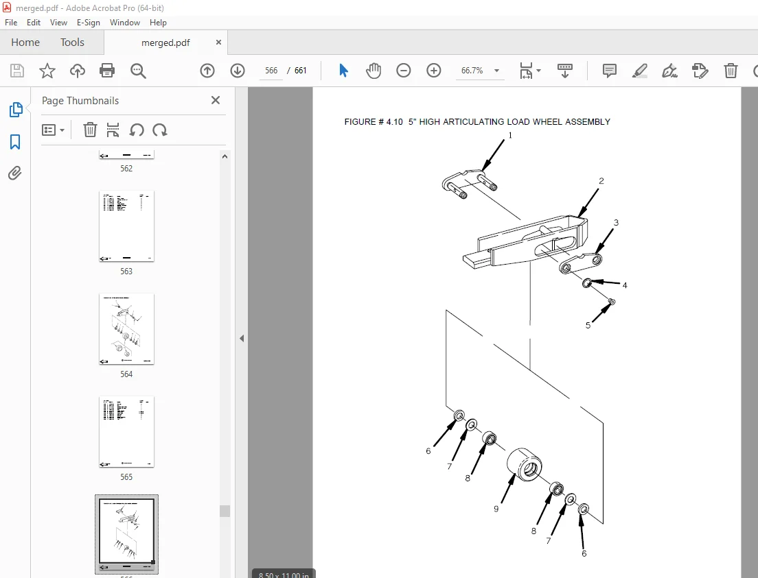
Figure # 4 10 5″ High Articulating Load Wheel Assembly 566
Figure # 4 10A 5″ High Articulating Load Wheel Assembly 568
Figure # 4 11 4″ High Articulating Load Wheel Assembly 570
Figure # 4 12 Caster Assembly 572
Figure # 4 13 Hand Lift/Lower and Speed Control for 3 Function Control 574
Figure # 5 1 Two Stage Mast Installation 576
Figure # 5 2 Two Stage Inner Column Assembly 578
Figure # 5 3 Two Stage Outer Column Assembly 580
Figure # 5 4 Two Stage Cylinder Installation 582
Figure # 5 5 Two Stage Lift Frame Assembly 584
Figure # 5 6 Two Stage Sideshifter Assembly 586
Figure # 5 7 Two Stage Fork Assembly 588
Figure # 5 8 Three Stage Mast Installation 590
Figure # 5 9 Three Stage Inner Column Assembly 592
Figure # 5 10 Three Stage Freelift Cylinder Installation 594
Figure # 5 11 Three Stage Intermediate Column Assembly 596
Figure # 5 12 Three Stage Outer Column Assembly 598
Figure # 5 13 Three Stage Lift Frame Assembly 600
Figure # 5 14 Three Stage Sideshifter Assembly 602
Figure # 5 15 Three Stage Fork Assembly 604
Figure # 6 1 Remote Lift/Lower EV-100 LX SCR Electrical Schematic 606
Figure # 6 2 Remote Lift/Lower EV-100 LX SCR Electrical Schematic Symbols 607
Figure # 6 3 Remote Lift/Lower Wiring Harness Assembly 608
Figure # 6 4 Remote Lift/Lower Three Stage Mast Cable Assembly 610
Figure # 6 5 Remote Lift/Lower Reach and Platform Cable Assembly 612
Figure # 6 6 Remote Lift/Lower Power Component Wiring 614
Figure # 6 7 Remote Lift/Lower Connector Assembly 616
Figure # 6 8 Remote Lift/Lower Hydraulic Schematic 618
Figure # 6 9 Remote Lift/Lower Manlift Hydraulic Schematic Symbols 619
Figure # 6 10 Remote Lift/Lower Hydraulic Diagram 620
Figure # 6 11 Blocking Remote Lift/Lower Valve Assembly 622
Figure # 6 12 Remote Lift/Lower Valve Assembly 624
Figure # 6 13 Remote Lift/Lower Load Backrest Installation 626
Figure # 6 14 Remote Lift/Lower Contactor Assembly 628
Figure # 7 1 Battery Lift Interrupt “E” EV-100LX SCR Electrical Schematic 630
Figure # 7 2 Battery Lift Interrupt “E” EV-100LX SCR Electrical Schematic Symbols 631
Figure # 7 1A Battery Lift Interrupt “E” for 3 Function Control Handle 632
Figure # 7 2A Battery Lift Interrupt “E” EV-100LX SCR Electrical Schematic Symbols 633
Figure # 7 3 Battery Lift Interrupt “EE” EV-100LX SCR Electrical Schematic 634
Figure # 7 4 Battery Lift Interrupt “EE” EV-100LX SCR Electrical Schematic Symbols 635
Figure # 7 3A Battery Lift Interrupt “EE” for 3 Function Control Handle 636
Figure # 7 4A Battery Lift Interrupt “EE” EV-100LX SCR Electrical Schematic Symbols 637
Figure # 7 5 Battery Lift Interrupt Installation 638
Figure # 10 1 Special Tools and Lubrications 640
Numerical Index 643
DESCRIPTION:
PARTS ORDERING INSTRUCTIONS:
HOW TO ORDER:
- When you order, supply the part number, quantity, model and serial numbers of your machine. Supplying this information will assure prompt, efficient handling of your order. The pictorial reference number is not needed and including it can only add confusion.
- Since your dealer carries many parts in stock and maintains up-to-date prices on all parts, he will be able to process your order immediately. If, for some reason, the part is not in stock, he will order it from the factory. In either event, he maintains a current file of service manuals, which give all available parts ordering or technical information.
- All prices are FOB factory in Muscatine, Iowa. Shipping charges are added to the price of the part shipping from the factory.
WHERE TO ORDER
Always order parts from the dealer who sold you your BT PRIME-MOVER. If it is necessary for the dealer to order parts from the factory, he is able to get prompt service for you. Parts are shipped in accordance with shipping instructions given on the order.
S.V 20/01/2025