BT Prime Mover RR-45 Reach Truck Parts Manual 300378-000 – PDF DOWNLOAD
$35.95
BT Prime Mover RR-45 Reach Truck Parts Manual 300378-000 – PDF DOWNLOAD
Description
BT Prime Mover RR-45 Reach Truck Parts Manual 300378-000 – PDF DOWNLOAD
FILE DETAILS:
BT Prime Mover RR-45 Reach Truck Parts Manual 300378-000 – PDF DOWNLOAD
Language : English
Pages : 1429
Downloadable : Yes
File Type : PDF
IMAGES PREVIEW OF THE MANUAL:
TABLE OF CONTENTS:
BT Prime Mover RR-45 Reach Truck Parts Manual 300378-000 – PDF DOWNLOAD
Front Cover 1
Parts Ordering Instructions 2
General Information 3
Alphabetical Index 4
Figure # 0 1 Decal and Parts Assembly 6
Figure # 0 2 Parts List and Service Reference Index 8
Figure # 1 1 Transmission and Steering Installation 10
Figure # 1 2 Drive Motor and Brake Assembly 12
Figure # 1 3 Transmission Assembly Part # 1 14
Figure # 1 4 Transmission Assembly Part # 2 16
Figure # 2 1 EV-100 Electrical Schematic 18
Figure # 2 2 Electrical Schematic Symbols 19
Figure # 2 3 Wiring Assembly for Cold Storage 20
Figure # 2 4 Wiring Harness Assembly 22
Figure # 2 5 Master Control Switch 24
Figure # 2 6 Limit Switch Wiring Harness Assembly 26
Figure # 2 7 Two Stage Mast Cable Assembly 28
Figure # 2 8 Three Stage Mast Cable Assembly 30
Figure # 2 9 Single Reach Cable Assembly 32
Figure # 2 10 Double Reach Cable Assembly 34
Figure # 2 11 Power Component Wiring 36
Figure # 2 12 EV-100 SCR Contactor Panel Assembly 38
Figure # 2 13 EV-100 SCR Control 40
Figure # 2 14 EV-100 SCR Forward & Rearward Contactor Assembly 42
Figure # 2 15 EV-100 SCR Lift Pump and 1A Contactor Assembly 44
Figure # 2 16 EV-100 SCR Power Steering Contactor Assembly 46
Figure # 2 17 Connector Assembly 48
Figure # 2 18 Lift Motor Assembly 50
Figure # 2 19 Drive Motor Assembly 52
Figure # 2 20 Auxiliary Motor Assembly 54
Figure # 2 21 Warning Light Assembly 56
Figure # 3 1 Hydraulic Schematic 58
Figure # 3 2 Hydraulic Schematic Symbols 59
Figure # 3 3 Auxiliary Pump and Reservoir Assembly 60
Figure # 3 4 Auxiliary Control Valve Assembly 62
Figure # 3 5 Auxiliary Pump Assembly 64
Figure # 3 6 Hydraulic Reservoir Assembly 66
Figure # 3 7 Steering Control Valve Assembly 68
Figure # 3 8 Steering Control Valve and Hose Assembly 70
Figure # 3 9 Steering Cylinder Assembly 72
Figure # 3 10 Two Stage Mast Hydraulic Assembly 74
Figure # 3 11 Three Stage Mast Hydraulic Assembly 76
Figure # 3 12 Single Reach, Reach Cylinder Hose Installation 78
Figure # 3 13 Single Reach Diverter Valve Assembly 80
Figure # 3 14 Single Reach, Reach Cylinder Assembly 82
Figure # 3 15 Single Reach, Tilt and Sideshift Hose Installation 84
Figure # 3 16 Tilt Cylinder Assembly 86
Figure # 3 17 Double Reach with Tilt and Sideshifter 88
Figure # 3 18 Double Reach Diverter Valve Assembly 90
Figure # 3 19 Double Reach, Reach Cylinder Assembly 92
Figure # 3 20 Lift Pump and Reservoir Assembly 94
Figure # 3 21 Lift Pump and Motor Assembly 96
Figure # 3 22 24 Volt Lift Pump Assembly 98
Figure # 3 23 36 Volt Lift Pump Assembly 100
Figure # 3 24 Lift Control Valve Assembly 102
Figure # 3 25 Two Stage Cylinder and Reservoir Assembly 104
Figure # 3 26 Two Stage Cylinder Assembly 106
Figure # 3 27 Three Stage Cylinder and Reservoir Assembly 108
Figure # 3 28 Three Stage Staging Cylinder Assembly 110
Figure # 3 29 Three Stage Freelift Cylinder Assembly 112
Figure # 3 30 Brake Master Cylinder 114
Figure # 3 31 Drive Motor Brake Cylinder 116
Figure # 3 32 Idler Wheel Brake Cylinder 118
Figure # 4 1 Shielding Assembly 120
Figure # 4 2 Emergency Disconnect Assembly 122
Figure # 4 3 Auxiliary Control Assembly 124
Figure # 4 4 Hand Lift/Lower and Speed Control 126
Figure # 4 5 Brake Linkage and Cylinder Assembly 128
Figure # 4 6 Steering Control Assembly 130
Figure # 4 7 Idler Wheel Installation 132
Figure # 4 8 Idler Wheel Assembly 134
Figure # 4 9 Main Frame and Load Wheel Assembly 136
Figure # 4 10 Single Load Wheel Assembly 138
Figure # 4 11 5″ High Articulating Load Wheel Assembly 140
Figure # 4 12 4″ High Articulating Load Wheel 142
Figure # 5 1 Two Stage Mast Installation 144
Figure # 5 2 Two Stage Inner Column Assembly 146
Figure # 5 3 Two Stage Outer Column Assembly 148
Figure # 5 4 Two Stage Cylinder Installation 150
Figure # 5 5 Single Reach Assembly 152
Figure # 5 6 Single Reach with Front Frame 154
Figure # 5 7 Double Reach Assembly 156
Figure # 5 8 Double Reach with Front Frame 158
Figure # 5 9 Sideshifter Assembly 160
Figure # 5 10 Fork Assembly 162
Figure # 5 11 Three Stage Mast Installation 164
Figure # 5 12 Three Stage Inner Column Assembly 166
Figure # 5 13 Three Stage Freelift Cylinder Installation 168
Figure # 5 14 Three Stage Intermediate Column Assembly 170
Figure # 5 15 Three Stage Outer Column Assembly 172
Figure # 6 1 Manlift Electrical Schematic 174
Figure # 6 2 Manlift Electrical Schematic Symbols 175
Figure # 6 3 Manlift Wiring Harness Assembly 176
Figure # 6 4 Manlift Three Stage Mast Cable Assembly 178
Figure # 6 5 Manlift Reach and Platform Cable Assembly 180
Figure # 6 7 Manlift Connector Assembly 182
Figure # 6 8 Manlift Hydraulic Schematic 184
Figure # 6 9 Manlift Hydraulic Schematic Symbols 185
Figure # 6 10 Manlift Hydraulic Diagram 186
Figure # 6 11 Manlift Valve Assembly 188
Figure # 6 12 Manlift Valve Assembly 190
Figure # 6 13 Manlift Load Backrest Installation 192
Figure # 7 1 Special Tools and Lubrications 194
Front Cover 196
Parts Ordering Instructions 197
General Information 198
Alphabetical Index 199
Figure # 0 1 Decals and Parts Assembly 203
Figure # 0 2 Parts List Index 205
Figure # 1 1 Transmission and Steering Installation 209
Figure # 1 2 Drive Motor Brake Assembly 211
Figure # 1 3 Transmission Assembly 213
Figure # 1 4 Transmission Assembly 215
Figure # 2 1 “E” EV-100LX SCR Electrical Schematic 217
Figure # 2 2 “E” EV-100LX SCR Electrical Schematic Symbols 218
Figure # 2 3 “EE” EV-100LX SCR Electrical Schematic 219
Figure # 2 4 “EE” EV-100LX SCR Electrical Schematic Symbols 220
Figure # 2 5 Wiring Assembly for Cold Storage 221
Figure # 2 6 Wiring Harness Assembly 223
Figure # 2 7 Limit Switch Wiring Assembly 225
Figure # 2 8 Two Stage Mast Cable Assembly 227
Figure # 2 9 Three Stage Mast Cable Assembly 229
Figure # 2 10 Single Reach Cable Assembly 231
Figure # 2 11 Double Reach Cable Assembly 233
Figure # 2 12 EV-100LX Power Component Wiring 235
Figure # 2 13 EV-100LX TX & TT SCR Control Panel Assembly 237
Figure # 2 14 EV-100LX Contactor Panel Assembly & Related Parts for “E” and “EE” 239
Figure # 2 15 EV-100LX Contactor Panel Assembly 241
Figure # 2 16 EV-100LX SCR Forward & Rearward Contactor Assembly 243
Figure # 2 17 EV-100LX SCR 1A Contactor Assembly 245
Figure # 2 18 Lift Pump Contactor Assembly 247
Figure # 2 19 EV-100LX SCR Auxiliary Pump Contactor Assembly 249
Figure # 2 20 Power Connector Assembly 251
Figure # 2 21 Lift Pump Motor Assembly 253
Figure # 2 22 Drive Motor Assembly 255
Figure # 2 23 Auxiliary Pump Motor Assembly 257
Figure # 2 24 Warning Light Assembly 259
Figure # 2 25 “E” EV-100LX TT SCR Electrical Schematic 261
Figure # 2 26 “E” EV-100LX TT SCR Electrical Schematic Symbols 262
Figure # 2 27 “EE” EV-100LX TT SCR Electrical Schematic 263
Figure # 2 28 “EE” EV-100LX TT SCR Electrical Schematic Symbols 264
Figure # 2 29 EV-100LX Dash Display Installation 265
Figure # 3 1 Hydraulic Schematic 267
Figure # 3 2 Hydraulic Schematic Symbols 268
Figure # 3 3 Auxiliary Pump and Reservoir Assembly 269
Figure # 3 4 Auxiliary Control Valve Assembly 271
Figure # 3 5 Auxiliary Pump and Motor Assembly 273
Figure # 3 6 Auxiliary Pump Assembly 275
Figure # 3 7 Hydraulic Reservoir Assembly 277
Figure # 3 8 Steering Control Valve Assembly 279
Figure # 3 9 Steering Control Valve and Hose Assembly 281
Figure # 3 10 Steering Cylinder Assembly 283
Figure # 3 11 Two Stage Mast Hydraulic Assembly 285
Figure # 3 12 Three Stage Mast Hydraulic Assembly 287
Figure # 3 13 Single Reach, Reach Cylinder Hose Installation 289
Figure # 3 14 Single Reach Diverter Valve Assembly 291
Figure # 3 15 Single Reach, Reach Cylinder Assembly 293
Figure # 3 16 Single Reach, Tilt and Sideshift Hose Installation 295
Figure # 3 17 Single Reach, Tilt Cylinder Assembly 297
Figure # 3 18 Double Reach with Tilt and Sideshifter 299
Figure # 3 19 Double Reach Diverter Valve Assembly 301
Figure # 3 20 Double Reach, Reach Cylinder Assembly 303
Figure # 3 21 Double Reach, Tilt Cylinder Assembly 305
Figure # 3 22 Lift Pump and Reservoir Assembly 307
Figure # 3 23 Lift Pump Motor Assembly 309
Figure # 3 24 Lift Pump Motor Assembly, 24 Volt 311
Figure # 3 25 Lift Pump Motor Assembly, 36 Volt 313
Figure # 3 26 Lift Control Valve Assembly 315
Figure # 3 27 Two Stage Cylinder and Reservoir Assembly 317
Figure # 3 28 Two Stage Cylinder Assembly 319
Figure # 3 29 Three Stage Cylinder and Reservoir Assembly 321
Figure # 3 30 Three Stage Staging Cylinder Assembly 323
Figure # 3 31 Three Stage Freelift Cylinder Assembly 325
Figure # 3 32 Brake Linkage and Cylinder Assembly 327
Figure # 3 33 Brake Master Cylinder 329
Figure # 3 34 Drive Motor Brake Cylinder 331
Figure # 3 35 Idler Wheel Brake Cylinder 333
Figure # 4 1 Shielding Assembly 335
Figure # 4 2 Emergency Disconnect Assembly 337
Figure # 4 3 Auxiliary Control Assembly 339
Figure # 4 4 Hand Lift/Lower and Speed Control 341
Figure # 4 5 Steering Control Assembly 343
Figure # 4 6 Idler Wheel Installation 345
Figure # 4 7 Idler Wheel Assembly 347
Figure # 4 8 Main Frame and Load Wheel Assembly 349
Figure # 4 9 Single Load Wheel Assembly 351
Figure # 4 10 5″ High Articulating Load Wheel Assembly 353
Figure # 4 11 4″ High Articulating Load Wheel Assembly 355
Figure # 5 1 Two Stage Mast Installation 357
Figure # 5 2 Two Stage Inner Column Assembly 359
Figure # 5 3 Two Stage Outer Column Assembly 361
Figure # 5 4 Two Stage Cylinder Installation 363
Figure # 5 5 Two Stage Single Reach Assembly 365
Figure # 5 6 Two Stage Single Reach Front Frame Assembly 367
Figure # 5 7 Two Stage Double Reach Assembly 369
Figure # 5 8 Two Stage Double Reach Front Frame Assembly 371
Figure # 5 9 Two Stage Sideshifter Assembly 373
Figure # 5 10 Two Stage Fork Assembly 375
Figure # 5 11 Three Stage Mast Installation 377
Figure # 5 12 Three Stage Inner Column Assembly 379
Figure # 5 13 Three Stage Freelift Cylinder Installation 381
Figure # 5 14 Three Stage Intermediate Column Assembly 383
Figure # 5 15 Three Stage Outer Column Assembly 385
Figure # 5 16 Three Stage Single Reach Assembly 387
Figure # 5 17 Three Stage Single Reach Front Frame Assembly 389
Figure # 5 18 Three Stage Double Reach Assembly 391
Figure # 5 19 Three Stage Double Reach Front Frame Assembly 393
Figure # 5 20 Three Stage Sideshifter Assembly 395
Figure # 5 21 Three Stage Fork Assembly 397
Figure # 6 1 Manlift EV-100 LX SCR Electrical Schematic 399
Figure # 6 2 Manlift EV-100 LX SCR Electrical Schematic Symbols 400
Figure # 6 3 Manlift Wiring Harness Assembly 401
Figure # 6 4 Manlift Three Stage Mast Cable Assembly 403
Figure # 6 5 Manlift Reach and Platform Cable Assembly 405
Figure # 6 6 Manlift Power Component Wiring 407
Figure # 6 7 Manlift Connector Assembly 409
Figure # 6 8 Manlift Hydraulic Schematic 411
Figure # 6 9 Manlift Hydraulic Schematic Symbols 412
Figure # 6 10 Manlift Hydraulic Diagram 413
Figure # 6 11 Blocking Manlift Valve Assembly 415
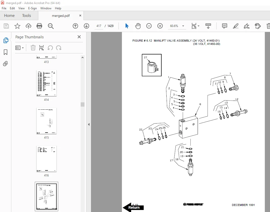
Figure # 6 12 Manlift Valve Assembly 417
Figure # 6 13 Manlift Load Backrest Installation 419
Figure # 10 1 Special Tools and Lubrications 421
Numerical Index 424
Front Cover 445
Parts Ordering Instructions 446
Field Modifications 446
General Information 447
Alphabetical Index 448
Figure # 0 1 Decals and Parts Assembly 452
Figure # 1 1 Transmission and Steering Installation 454
Figure # 1 2 Drive Motor Brake Assembly 456
Figure # 1 3 Transmission Assembly Part #1 458
Figure # 1 4 Transmission Assembly Part #2 460
Figure # 2 1 “E” EV-100LX SCR Electrical Schematic 462
Figure # 2 2 “E” EV-100LX SCR Electrical Schematic Symbols 463
Figure # 2 3 “EE” EV-100LX SCR Electrical Schematic 464
Figure # 2 4 “EE” EV-100LX SCR Electrical Schematic Symbols 465
Figure # 2 5 Wiring Assembly for Cold Storage 466
Figure # 2 6 Wiring Harness Assembly 468
Figure # 2 7 Limit Switch Wiring Assembly 470
Figure # 2 8 Two Stage Mast Cable Assembly 472
Figure # 2 9 Three Stage Mast Cable Assembly 474
Figure # 2 10 Single Reach Cable Assembly 476
Figure # 2 11 Double Reach Cable Assembly 478
Figure # 2 12 EV-100LX Power Component Wiring 480
Figure # 2 13 EV-100LX TX & TT SCR Control Panel Assembly 482
Figure # 2 14 EV-100LX Contactor Panel Assembly & Related Parts for “E” and “EE” 484
Figure # 2 15 EV-100LX Contactor Panel Assembly 486
Figure # 2 16 EV-100LX SCR Forward & Rearward Contactor Assembly 488
Figure # 2 17 EV-100LX SCR 1A Contactor Assembly 490
Figure # 2 18 Lift Pump Contactor Assembly 492
Figure # 2 19 EV-100LX SCR Auxiliary Pump Contactor Assembly 494
Figure # 2 20 Power Connector Assembly 496
Figure # 2 21 Lift Pump Motor Assembly 498
Figure # 2 22 Drive Motor Assembly 500
Figure # 2 23 Auxiliary Pump Motor Assembly 502
Figure # 2 24 Warning Light Assembly 504
Figure # 2 25 “E” EV-100LX TT SCR Electrical Schematic 506
Figure # 2 26 “E” EV-100LX TT SCR Electrical Schematic Symbols 507
Figure # 2 27 “EE” EV-100LX TT SCR Electrical Schematic 508
Figure # 2 28 “EE” EV-100LX TT SCR Electrical Schematic Symbols 509
Figure # 2 29 EV-100LX Dash Display Installation 510
Figure # 2 30 EV-100LX SCR Electrical Schematic – 3 Function Control Handle 512
Figure # 2 31 EV-100LX SCR Electrical Schematic Symbols 513
Figure # 2 32 Wiring Harness Assembly for 3 Function Control Valve 514
Figure # 3 1 Hydraulic Schematic 516
Figure # 3 2 Hydraulic Schematic Symbols 517
Figure # 3 3 Auxiliary Pump and Reservoir Assembly 518
Figure # 3 4 Auxiliary Control Valve Assembly 520
Figure # 3 5 Auxiliary Pump and Motor Assembly 522
Figure # 3 6 Auxiliary Pump Assembly 524
Figure # 3 7 Hydraulic Reservoir Assembly 526
Figure # 3 8 Steering Control Valve Assembly 528
Figure # 3 9 Steering Control Valve and Hose Assembly 530
Figure # 3 10 Steering Cylinder Assembly 532
Figure # 3 11 Two Stage Mast Hydraulic Assembly 534
Figure # 3 12 Three Stage Mast Hydraulic Assembly 536
Figure # 3 13 Single Reach, Reach Cylinder Hose Installation 538
Figure # 3 14 Single Reach Diverter Valve Assembly 540
Figure # 3 15 Single Reach, Reach Cylinder Assembly 542
Figure # 3 16 Single Reach, Tilt and Sideshift Hose Installation 544
Figure # 3 17 Single Reach, Tilt Cylinder Assembly 546
Figure # 3 18 Double Reach with Tilt and Sideshifter 548
Figure # 3 19 Double Reach Diverter Valve Assembly 550
Figure # 3 20 Double Reach, Reach Cylinder Assembly 552
Figure # 3 21 Double Reach, Tilt Cylinder Assembly 554
Figure # 3 22 Lift Pump and Reservoir Assembly 558
Figure # 3 23 Lift Pump Motor Assembly 560
Figure # 3 24 Lift Pump Assembly 562
Figure # 3 25 Lift Pump Motor Assembly, 36 Volt 564
Figure # 3 26 Lift Control Valve Assembly 566
Figure # 3 27 Two Stage Cylinder and Reservoir Assembly 568
Figure # 3 28 Two Stage Cylinder Assembly 570
Figure # 3 29 Three Stage Cylinder and Reservoir Assembly 572
Figure # 3 30 Three Stage Staging Cylinder Assembly 574
Figure # 3 31 Three Stage Freelift Cylinder Assembly 576
Figure # 3 32 Brake Linkage and Cylinder Assembly 578
Figure # 3 33 Brake Master Cylinder 580
Figure # 3 34 Drive Motor Brake Cylinder 582
Figure # 3 35 Idler Wheel Brake Cylinder 584
Figure # 3 36 Hydraulic Schematic for 3 Function Control Handle 586
Figure # 3 37 Hydraulic Schematic Symbols 587
Figure # 3 38 Auxiliary Pump & Reservoir Assembly for 3 Function Control Handle 588
Figure # 3 39 Valve Assembly 590
Figure # 3 40 Two Stage Mast Hydraulic Assembly for 3 Function Control Handle 592
Figure # 3 41 Three Stage Mast Hydraulic Assembly for 3 Function Control Handle 594
Figure # 4 1 Shielding Assembly 596
Figure # 4 2 Emergency Disconnect Assembly 598
Figure # 4 3 Auxiliary Control Assembly 600
Figure # 4 4 Hand Lift/Lower and Speed Control 602
Figure # 4 5 Steering Control Assembly 604
Figure # 4 6 Idler Wheel Installation 606
Figure # 4 7 Idler Wheel Assembly 608
Figure # 4 8 Main Frame and Load Wheel Assembly 610
Figure # 4 9 Single Load Wheel Assembly 612
Figure # 4 10 5″ High Articulating Load Wheel Assembly 614
Figure # 4 11 4″ High Articulating Load Wheel Assembly 616
Figure # 4 12 Hand Lift/Lower and Speed Control for 3 Function Control 618
Figure # 5 1 Two Stage Mast Installation 620
Figure # 5 2 Two Stage Inner Column Assembly 622
Figure # 5 3 Two Stage Outer Column Assembly 624
Figure # 5 4 Two Stage Cylinder Installation 626
Figure # 5 5 Two Stage Single Reach Assembly 628
Figure # 5 6 Two Stage Single Reach Front Frame Assembly 630
Figure # 5 7 Two Stage Double Reach Assembly 632
Figure # 5 8 Two Stage Double Reach Front Frame Assembly 634
Figure # 5 9 Two Stage Sideshifter Assembly 636
Figure # 5 10 Two Stage Fork Assembly 638
Figure # 5 11 Three Stage Mast Installation 640
Figure # 5 12 Three Stage Inner Column Assembly 642
Figure # 5 13 Three Stage Freelift Cylinder Installation 644
Figure # 5 14 Three Stage Intermediate Column Assembly 646
Figure # 5 15 Three Stage Outer Column Assembly 648
Figure # 5 16 Three Stage Single Reach Assembly 650
Figure # 5 17 Three Stage Single Reach Front Frame Assembly 652
Figure # 5 18 Three Stage Double Reach Assembly 654
Figure # 5 19 Three Stage Double Reach Front Frame Assembly 656
Figure # 5 20 Three Stage Sideshifter Assembly 658
Figure # 5 21 Three Stage Fork Assembly 660
Figure # 6 1 Remote Lift/Lower EV-100 LX SCR Electrical Schematic 662
Figure # 6 2 Remote Lift/Lower EV-100 LX SCR Electrical Schematic Symbols 663
Figure # 6 3 Manlift Wiring Harness Assembly 664
Figure # 6 4 Remote Lift/Lower Three Stage Mast Cable Assembly 666
Figure # 6 5 Remote Lift/Lower Reach and Platform Cable Assembly 668
Figure # 6 6 Remote Lift/Lower Power Component Wiring 670
Figure # 6 7 Remote Lift/Lower Connector Assembly 672
Figure # 6 8 Remote Lift/Lower Hydraulic Schematic 674
Figure # 6 9 Remote Lift/Lower Manlift Hydraulic Schematic Symbols 675
Figure # 6 10 Remote Lift/Lower Hydraulic Diagram 676
Figure # 6 11 Blocking Remote Lift/Lower Valve Assembly 678
Figure # 6 12 Remote Lift/Lower Valve Assembly 680
Figure # 6 13 Remote Lift/Lower Load Backrest Installation 682
Figure # 7 1 Battery Lift Interrupt “E” EV-100LX SCR Electrical Schematic 684
Figure # 7 2 Battery Lift Interrupt “E” EV-100LX SCR Electrical Schematic Symbols 685
Figure # 7 3 Battery Lift Interrupt “EE’ EV-100LX SCR Electrical Schematic 686
Figure # 7 4 Battery Lift Interrupt “EE” EV-100LX SCR Electrical Schematic Symbols 687
Figure # 7 5 Battery Lift Interrupt Installation 688
Figure # 10 1 Special Tools and Lubrications 690
Numerical Index 693
Front Cover 713
Parts Ordering Instructions 714
General Information 715
Alphabetical Index 716
Figure # 0 1 Decals and Parts Assembly 720
Figure # 1 1 Transmission and Steering Installation 722
Figure # 1 2 Drive Motor Brake Assembly 724
Figure # 1 3 Transmission Assembly Part # I 726
Figure # 1 4 Transmission Assembly Part # II 728
Figure # 2 1 “E” EV-100LX SCR Electrical Schematic 730
Figure # 2 2 “E” EV-100LX SCR Electrical Schematic Symbols 731
Figure # 2 3 “EE” EV-100LX SCR Electrical Schematic 732
Figure # 2 4 “EE” EV-100LX SCR Electrical Schematic Symbols 733
Figure # 2 5 Wiring Assembly for Cold Storage 734
Figure # 2 6 Wiring Harness Assembly 736
Figure # 2 7 Limit Switch Wiring Assembly 738
Figure # 2 8 Two Stage Mast Cable Assembly 740
Figure # 2 9 Three Stage Mast Cable Assembly 742
Figure # 2 10 Single Reach Cable Assembly 744
Figure # 2 11 Double Reach Cable Assembly 746
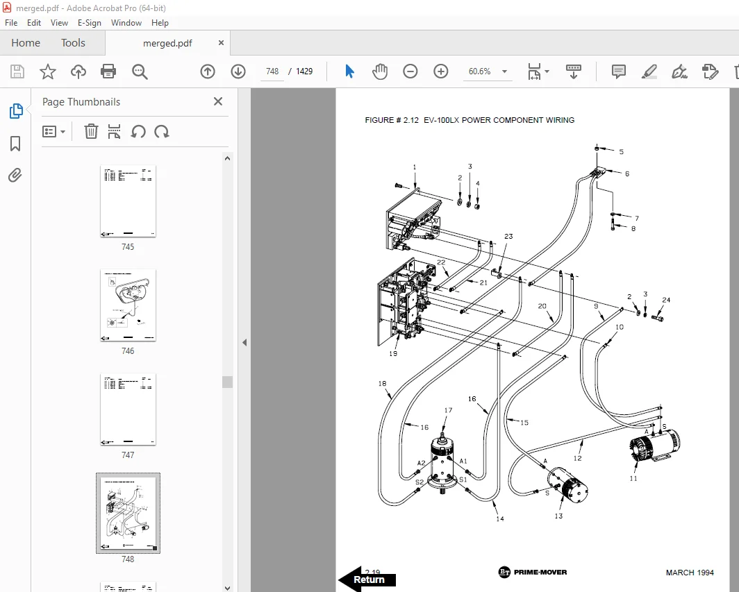
Figure # 2 12 EV-100LX Power Component Wiring 748
Figure # 2 13 EV-100LX TX & TT SCR Control Panel Assembly 750
Figure # 2 14 EV-100LX Contactor Panel Assembly & Related Parts for “E” and “EE” 752
Figure # 2 15 Contactor Panel Assembly 754
Figure # 2 16 EV-100LX SCR Forward & Rearward Contactor Assembly 756
Figure # 2 17 EV-100LX SCR 1A Contactor Assembly 758
Figure # 2 18 Lift Pump Contactor Assembly 760
Figure # 2 19 EV-100LX SCR Auxiliary Pump Contactor Assembly 762
Figure # 2 20 Power Connector Assembly 764
Figure # 2 21 Lift Pump Motor Assembly 766
Figure # 2 21A Lift Pump Motor Assembly, 36 Volt 768
Figure # 2 22 Drive Motor Assembly 770
Figure # 2 23 Auxiliary Pump Motor Assembly 772
Figure # 2 24 Warning Light Assembly 774
Figure # 2 25 “E” EV-100LX TT SCR Electrical Schematic 776
Figure # 2 26 “E” EV-100LX TT SCR Electrical Schematic Symbols 777
Figure # 2 27 “EE” EV-100LX TT SCR Electrical Schematic 778
Figure # 2 28 “EE” EV-100LX TT SCR Electrical Schematic Symbols 779
Figure # 2 29 EV-100LX Dash Display Installation 780
Figure # 2 30 EV-100LX SCR Electrical Schematic – 3 Function Control Handle 782
Figure # 2 31 EV-100LX SCR Electrical Schematic Symbols 783
Figure # 2 30A TX EV-100LX Electrical Schematic – 3 Function Control Handle 784
Figure # 2 31A EV-100LX SCR Electrical Schematic Symbols 785
Figure # 2 30B TT EV-100LX Electrical Schematic – 3 Function Control Handle 786
Figure # 2 31B EV-100LX SCR Electrical Schematic Symbols 787
Figure # 2 32 Wiring Harness Assembly for 3 Function Control Valve 788
Figure # 3 1 Hydraulic Schematic 790
Figure # 3 2 Hydraulic Schematic Symbols 791
Figure # 3 3 Auxiliary Pump and Reservoir Assembly 792
Figure # 3 4 Auxiliary Control Valve Assembly 794
Figure # 3 5 Auxiliary Pump and Motor Assembly 796
Figure # 3 6 Auxiliary Pump Assembly 798
Figure # 3 7 Hydraulic Reservoir Assembly 800
Figure # 3 8 Steering Control Valve Assembly 802
Figure # 3 9 Steering Control Valve and Hose Assembly 804
Figure # 3 10 Steering Cylinder Assembly 806
Figure # 3 11 Two Stage Mast Hydraulic Assembly 808
Figure # 3 12 Three Stage Mast Hydraulic Assembly 810
Figure # 3 13 Single Reach, Reach Cylinder Hose Installation 812
Figure # 3 14 Single Reach Diverter Valve Assembly 814
Figure # 3 15 Single Reach, Reach Cylinder Assembly 816
Figure # 3 16 Single Reach, Tilt and Sideshift Hose Installation 818
Figure # 3 17 Single Reach, Tilt Cylinder Assembly 820
Figure # 3 18 Double Reach with Tilt and Sideshifter 822
Figure # 3 19 Double Reach Diverter Valve Assembly 824
Figure # 3 20 Double Reach, Reach Cylinder Assembly 826
Figure # 3 21 Double Reach, Tilt Cylinder Assembly 828
Figure # 3 22 Lift Pump and Reservoir Assembly 830
Figure # 3 23 Lift Pump Motor Assembly 832
Figure # 3 24 Lift Pump Assembly 834
Figure # 3 25 Lift Pump Motor Assembly, 36 Volt 836
Figure # 3 26 Lift Control Valve Assembly 838
Figure # 3 27 Two Stage Cylinder and Reservoir Assembly 840
Figure # 3 28 Two Stage Cylinder Assembly 842
Figure # 3 29 Three Stage Cylinder and Reservoir Assembly 844
Figure # 3 30 Three Stage Staging Cylinder Assembly 846
Figure # 3 31 Three Stage Freelift Cylinder Assembly 848
Figure # 3 32 Brake Linkage and Cylinder Assembly 850
Figure # 3 33 Brake Master Cylinder 852
Figure # 3 34 Drive Motor Brake Cylinder 854
Figure # 3 35 Idler Wheel Brake Cylinder 856
Figure # 3 36 Hydraulic Schematic for 3 Function Control Handle 858
Figure # 3 37 Hydraulic Schematic Symbols 859
Figure # 3 38 Auxiliary Pump & Reservoir Assy for 3 Function Control Handle 860
Figure # 3 39 Valve Assembly 862
Figure # 3 40 Two Stage Mast Hydraulic Assy for 3 Function Control Handle 864
Figure # 3 41 Three Stage Mast Hydraulic Assy for 3 Function Control Handle 866
Figure # 4 1 Shielding Assembly 868
Figure # 4 2 Emergency Disconnect Assembly 870
Figure # 4 3 Auxiliary Control Assembly 872
Figure # 4 4 Hand Lift/Lower and Speed Control 874
Figure # 4 5 Steering Control Assembly 876
Figure # 4 6 Idler Wheel Installation 878
Figure # 4 7 Idler Wheel Assembly 880
Figure # 4 8 Main Frame and Load Wheel Assembly 882
Figure # 4 9 Single Load Wheel Assembly 884
Figure # 4 9A Single Load Wheel Assembly 886
Figure # 4 10 5″ High Articulating Load Wheel Assembly 888
Figure # 4 10A 5″ High Articulating Load Wheel Assembly 890
Figure # 4 11 4″ High Articulating Load Wheel Assembly 892
Figure # 4 11A 4″ High Articulating Load Wheel Assembly 894
Figure # 5 1 Two Stage Mast Installation 896
Figure # 5 2 Two Stage Inner Column Assembly 898
Figure # 5 3 Two Stage Outer Column Assembly 900
Figure # 5 4 Two Stage Cylinder Installation 902
Figure # 5 5 Two Stage Single Reach Assembly 904
Figure # 5 6 Two Stage Single Reach Front Frame Assembly 906
Figure # 5 7 Two Stage Double Reach Assembly 908
Figure # 5 8 Two Stage Double Reach Front Frame Assembly 910
Figure # 5 9 Two Stage Sideshifter Assembly 912
Figure # 5 10 Two Stage Fork Assembly 914
Figure # 5 11 Three Stage Mast Installation 916
Figure # 5 12 Three Stage Inner Column Assembly 918
Figure # 5 13 Three Stage Freelift Cylinder Installation 920
Figure # 5 14 Three Stage Intermediate Column Assembly 922
Figure # 5 15 Three Stage Outer Column Assembly 924
Figure # 5 16 Three Stage Single Reach Assembly 926
Figure # 5 17 Three Stage Single Reach Front Frame Assembly 928
Figure # 5 18 Three Stage Double Reach Assembly 930
Figure # 5 19 Three Stage Double Reach Front Frame Assembly 932
Figure # 5 20 Three Stage Sideshifter Assy 934
Figure # 5 21 Three Stage Fork Assembly 936
Figure # 6 1 Remote Lift/Lower EV-100 LX SCR Electrical Schematic 938
Figure # 6 2 Remote Lift/Lower EV-100 LX SCR Electrical Schematic Symbols 939
Figure # 6 3 Remote Lift/Lower Wiring Harness Assembly 940
Figure # 6 4 Remote Lift/Lower Three Stage Mast Cable Assembly 942
Figure # 6 5 Remote Lift/Lower Reach and Platform Cable Assembly 944
Figure # 6 6 Remote Lift/Lower Power Component Wiring 946
Figure # 6 7 Remote Lift/Lower Connector Assembly 948
Figure # 6 8 Remote Lift/Lower Hydraulic Schematic 950
Figure # 6 9 Remote Lift/Lower Manlift Hydraulic Schematic Symbols 951
Figure # 6 10 Remote Lift/Lower Hydraulic Diagram 952
Figure # 6 11 Blocking Remote Lift/Lower Valve Assembly 954
Figure # 6 12 Remote Lift/Lower Valve Assembly 956
Figure # 6 13 Remote Lift/Lower Load Backrest Installation 958
Figure # 6 14 Remote Lift/Lower Contactor Assembly 960
Figure # 7 1 Battery Lift Interrupt “E” EV-100LX SCR Electrical Schematic 962
Figure # 7 2 Battery Lift Interrupt “E” EV-100LX SCR Electrical Schematic Symbols 963
Figure # 7 3 Battery Lift Interrupt “EE” EV-100LX SCR Electrical Schematic 964
Figure # 7 4 Battery Lift Interrupt “EE” EV-100LX SCR Electrical Schematic Symbols 965
Figure # 7 5 Battery Lift Interrupt Installation 966
Figure # 10 1 Special Tools and Lubrications 968
Numerical Index 971
Front Cover 995
Parts Ordering Instructions 996
General Information 997
Alphabetical Index 998
Figure # 0 1 Decals and Parts Assembly 1002
Figure # 1 1 Transmission and Steering Installation 1004
Figure # 1 2 Drive Motor & Related Parts 1006
Figure # 1 3 Transmission Assembly Part # I 1008
Figure # 1 4 Transmission Assembly Part # II 1010
Figure # 2 1 TX Electrical Schematic – Multi-Function Control 1012
Figure # 2 2 TT Electrical Schematic – Multi-Function Control 1013
Figure # 2 3 “Z” Lift TX Electrical Schematic – Multi-Function Control 1014
Figure # 2 4 “Z” Lift TT Electrical Schematic – Multi-Function Control 1015
Figure # 2 5 Wiring Assembly for Cold Storage 1016
Figure # 2 6 Lift Control Wiring Harness – Multi-Function Control 1018
Figure # 2 7 Limit Switch Wiring Assembly 1020
Figure # 2 8 Two Stage Mast Cable Assembly 1022
Figure # 2 9 Three Stage Mast Cable Assembly 1024
Figure # 2 10 Reach Cable Assembly 1026
Figure # 2 11 Power Component Wiring 1028
Figure # 2 12 SCR Control Panel 1030
Figure # 2 13 “Z” Lift Contactor Panel Assembly & Related Parts 1032
Figure # 2 14 Contactor Panel Assembly & Related Parts for “E” and “EE” 1034
Figure # 2 15 Contactor Panel Assembly 1036
Figure # 2 16 Forward & Rearward Contactor Assembly 1038
Figure # 2 17 Contactor Assembly 1040
Figure # 2 18 Power Connector Assembly 1042
Figure # 2 19 Lift Pump Motor Assembly 1044
Figure # 2 20 Drive Motor Assembly 1046
Figure # 2 21 Auxiliary Pump Motor Assembly 1048
Figure # 2 22 Warning Light and Work Light Assembly 1050
Figure # 2 23 EV-100LX Dash Display Installation 1052
Figure # 2 24 “E” Electrical Schematic – Single Function Control 1054
Figure # 2 25 “EE” Electrical Schematic – Single Function Control 1055
Figure # 2 26 “Z” Lift Electrical Schematic – Single Function Control 1056
Figure # 2 27 Electrical Schematic Symbols 1057
Figure # 2 28 Lift Control Wiring Harness – Single Function Control 1058
Figure # 2 29 Battery Lift Interrupt Installation 1060
Figure # 3 1 Hydraulic Schematic 1062
Figure # 3 2 Hydraulic Schematic Symbols 1063
Figure # 3 3 Auxiliary Pump & Reservoir Assembly 1064
Figure # 3 4 Auxiliary Control Valve & Related Parts 1066
Figure # 3 5 Two Stage Mast Hydraulic Assembly 1068
Figure # 3 6 Three Stage Mast Hydraulic Assembly 1070
Figure # 3 7 Single Reach, Reach Cylinder Hose Installation 1072
Figure # 3 8 Single Reach, Tilt and Sideshift Hose Installation 1074
Figure # 3 9 Double Reach with Tilt and Sideshifter 1076
Figure # 3 10 Steering Control Valve and Hose Assembly 1078
Figure # 3 11 Steering Cylinder Assembly 1080
Figure # 3 12 Lift Pump and Reservoir Assembly – Single Pump 1082
Figure # 3 13 “Z” Lift Pump Motor and Reservoir Assembly – Double Pump 1084
Figure # 3 14 Two Stage Cylinder and Reservoir Assembly 1086
Figure # 3 15 Two Stage Cylinder Assembly 1088
Figure # 3 16 Three Stage Cylinder & Reservoir Assembly – Single Pump 1090
Figure # 3 17 Three Stage Cylinder & Reservoir Assembly, “Z” Lift – Double Pump 1092
Figure # 3 18 Three Stage Staging Cylinder Assembly 1094
Figure # 3 19 Three Stage Freelift Cylinder Assembly 1096
Figure # 3 20 Hydraulic Reservoir Assembly 1098
Figure # 3 21 Auxiliary Control Valve Assembly – Single Function Control 1100
Figure # 3 22 Lift Control Valve Assembly 1102
Figure # 3 23 Valve Assembly – Multi-Function Control 1104
Figure # 3 24 Single Reach Diverter Valve Assembly 1106
Figure # 3 25 Double Reach Diverter Valve Assembly 1108
Figure # 3 26 Steering Control Valve Assembly 1110
Figure # 3 27 Lift Pump & Motor Assembly 1112
Figure # 3 28 Lift Pump Assembly 1114
Figure # 3 29 Lift Pump Assembly, 36 Volt “E” – Single Pump 1116
Figure # 3 30 Auxiliary Pump and Motor Assembly 1118
Figure # 3 31 Auxiliary Pump Assembly 1120
Figure # 3 32 Reach Cylinder Assembly 1122
Figure # 3 33 Tilt Cylinder Assembly 1124
Figure # 3 34 Brake Linkage and Cylinder Assembly 1126
Figure # 3 35 Brake Master Cylinder 1128
Figure # 3 36 Drive Motor Brake Cylinder 1130
Figure # 3 37 Idler Wheel Brake Cylinder 1132
Figure # 4 1 Shielding Assembly 1134
Figure # 4 2 Emergency Disconnect Assembly 1136
Figure # 4 3 Auxiliary Control Assembly – Single Function Control 1138
Figure # 4 4 Hand Lift/Lower and Speed Control – Multi-Function Control 1140
Figure # 4 5 Hand Lift/Lower and Speed Control – Single Function Control 1142
Figure # 4 6 Steering Control Assembly 1144
Figure # 4 7 Idler Wheel Installation 1146
Figure # 4 8 Idler Wheel Assembly 1148
Figure # 4 9 Main Frame and Load Wheel Assembly 1150
Figure # 4 10 5″ High Articulating Load Wheel Assembly 1152
Figure # 4 11 Single Load Wheel Assembly 1154
Figure # 4 12 4″ High Articulating Load Wheel Assembly 1156
Figure # 5 1 Two Stage Mast Installation 1158
Figure # 5 2 Two Stage Inner Column Assembly 1160
Figure # 5 3 Two Stage Outer Column Assembly 1162
Figure # 5 4 Two Stage Cylinder Installation 1164
Figure # 5 5 Three Stage Mast Installation 1166
Figure # 5 6 Three Stage Inner Column Assembly 1168
Figure # 5 7 Three Stage Freelift Cylinder Installation 1170
Figure # 5 8 Three Stage Intermediate Column Assembly 1172
Figure # 5 9 Three Stage Outer Column Assembly 1174
Figure # 5 10 Single Reach Assembly 1176
Figure # 5 11 Single Reach Front Frame Assembly 1178
Figure # 5 12 Double Reach Assembly 1180
Figure # 5 13 Double Reach Front Frame Assembly 1182
Figure # 5 14 Sideshifter Assembly 1184
Figure # 5 15 Fork Assembly 1186
Figure # 10 1 Special Tools and Lubrications 1188
Numerical Index 1191
Front Cover 1211
Parts Ordering Instructions 1212
General Information 1213
Alphabetical Index 1214
Figure # 0 1 Decals and Parts Assembly 1218
Figure # 1 1 Transmission and Steering Installation 1220
Figure # 1 2 Drive Motor & Related Parts 1222
Figure # 1 3 Transmission Assembly Part # I 1224
Figure # 1 4 Transmission Assembly Part II 1226
Figure # 2 1 TX Electrical Schematic – Multi-Function Control 1228
Figure # 2 2 TT Electrical Schematic – Multi-Function Control 1229
Figure # 2 3 “Z” Lift TX Electrical Schematic – Multi-Function Control 1230
Figure # 2 4 “Z” Lift TT Electrical Schematic – Multi-Function Control 1231
Figure # 2 5 Wiring Assembly for Cold Storage 1232
Figure # 2 6 Lift Control Wiring Harness – Multi-Function Control 1234
Figure # 2 7 Limit Switch Wiring Assembly 1236
Figure # 2 8 Two Stage Mast Cable Assembly 1238
Figure # 2 9 Three Stage Mast Cable Assembly 1240
Figure # 2 10 Reach Cable Assembly 1242
Figure # 2 11 Power Component Wiring 1244
Figure # 2 12 SCR Control Panel 1246
Figure # 2 13 “Z” Lift Contactor Panel Assembly & Related Parts 1248
Figure # 2 14 Contactor Panel Assembly & Related Parts for “E” and “EE” 1250
Figure # 2 15 Contactor Panel Assembly 1252
Figure # 2 16 Forward & Rearward Contactor Assembly 1254
Figure # 2 17 Contactor Assembly 1256
Figure # 2 18 Power Connector Assembly 1258
Figure # 2 19 Lift Pump Motor Assembly 1260
Figure # 2 20 Drive Motor Assembly 1262
Figure # 2 21 Auxiliary Pump Motor Assembly 1264
Figure # 2 22 Warning Light and Work Light Assembly 1266
Figure # 2 23 EV-100LX Dash Display Installation 1268
Figure # 2 24 “E” Electrical Schematic – Single Function Control 1270
Figure # 2 25 “EE” Electrical Schematic – Single Function Control 1271
Figure # 2 26 “Z” Lift Electrical Schematic – Single Function Control 1272
Figure # 2 27 Electrical Schematic Symbols 1273
Figure # 2 28 Lift Control Wiring Harness – Single Function Control 1274
Figure # 2 29 Battery Lift Interrupt Installation 1276
Figure # 3 1 Hydraulic Schematic 1278
Figure # 3 2 Hydraulic Schematic Symbols 1279
Figure # 3 3 Auxiliary Pump & Reservoir Assembly 1280
Figure # 3 4 Auxiliary Control Valve & Related Parts 1282
Figure # 3 5 Two Stage Mast Hydraulic Assembly 1284
Figure # 3 6 Three Stage Mast Hydraulic Assembly 1286
Figure # 3 7 Single Reach, Reach Cylinder Hose Installation 1288
Figure # 3 8 Single Reach, Tilt and Sideshift Hose Installation 1290
Figure # 3 9 Double Reach with Tilt and Sideshifter 1292
Figure # 3 10 Steering Control Valve and Hose Assembly 1294
Figure # 3 11 Steering Cylinder Assembly 1296
Figure # 3 12 Lift Pump and Reservoir Assembly – Single Pump 1298
Figure # 3 13 “Z” Lift Pump Motor and Reservoir Assembly – Double Pump 1300
Figure # 3 14 Two Stage Cylinder and Reservoir Assembly 1302
Figure # 3 15 Two Stage Cylinder Assembly 1304
Figure # 3 16 Three Stage Cylinder & Reservoir Assembly – Single Pump 1306
Figure # 3 17 Three Stage Cylinder & Reservoir Assembly, “Z” Lift – Double Pump 1308
Figure # 3 18 Three Stage Staging Cylinder Assembly 1310
Figure # 3 19 Three Stage Freelift Cylinder Assembly 1312
Figure # 3 20 Hydraulic Reservoir Assembly 1314
Figure # 3 21 Auxiliary Control Valve Assembly – Single Function Control 1316
Figure # 3 22 Lift Control Valve Assembly 1318
Figure # 3 23 Valve Assembly – Multi-Function Control 1320
Figure # 3 24 Single Reach Diverter Valve Assembly 1322
Figure # 3 25 Double Reach Diverter Valve Assembly 1324
Figure # 3 26 Steering Control Valve Assembly 1326
Figure # 3 27 Lift Pump & Motor Assembly 1328
Figure # 3 28 Lift Pump Assembly 1330
Figure # 3 29 Lift Pump Assembly, 36 Volt “E” – Single Pump 1332
Figure # 3 30 Auxiliary Pump and Motor Assembly 1334
Figure # 3 31 Auxiliary Pump Assembly 1336
Figure # 3 32 Reach Cylinder Assembly 1338
Figure # 3 33 Tilt Cylinder Assembly 1340
Figure # 3 34 Brake Linkage and Cylinder Assembly 1342
Figure # 3 35 Brake Master Cylinder 1344
Figure # 3 36 Drive Motor Assembly 1346
Figure # 3 37 Idler Wheel Brake Cylinder 1348
Figure # 4 1 Shielding Assembly 1350
Figure # 4 2 Emergency Disconnect Assembly 1352
Figure # 4 3 Auxiliary Control Assembly – Single Function Control 1354
Figure # 4 4 Hand Lift/Lower and Speed Control – Multi-Function Control 1356
Figure # 4 5 Hand Lift/Lower and Speed Control – Single Function Control 1358
Figure # 4 6 Steering Control Assembly 1360
Figure # 4 7 Idler Wheel Installation 1362
Figure # 4 8 Idler Wheel Assembly 1364
Figure # 4 9 Main Frame and Load Wheel Assembly 1366
Figure # 4 10 5″ High Articulating Load Wheel Assembly 1368
Figure # 4 11 Single Load Wheel Assembly 1370
Figure # 4 12 4″ High Articulating Load Wheel Assembly 1372
Figure # 5 1 Two Stage Mast Installation 1374
Figure # 5 2 Two Stage Inner Column Assembly 1376
Figure # 5 3 Two Stage Outer Column Assembly 1378
Figure # 5 4 Two Stage Cylinder Installation 1380
Figure # 5 5 Three Stage Mast Installation 1382
Figure # 5 6 Three Stage Inner Column Assembly 1384
Figure # 5 7 Three Stage Freelift Cylinder Installation 1386
Figure # 5 8 Three Stage Intermediate Column Assembly 1388
Figure # 5 9 Three Stage Outer Column Assembly 1390
Figure # 5 10 Single Reach Assembly 1392
Figure # 5 11 Single Reach Front Frame Assembly 1394
Figure # 5 12 Double Reach Assembly 1396
Figure # 5 13 Double Reach Front Frame Assembly 1398
Figure # 5 14 Sideshifter Assembly 1400
Figure # 5 15 Fork Assembly 1402
Figure # 10 1 Special Tools and Lubrications 1404
Numerical Index 1407
DESCRIPTION:
BT Prime Mover RR-45 Reach Truck Parts Manual 300378-000 – PDF DOWNLOAD
PARTS ORDERING INSTRUCTIONS :
HOW TO ORDER:
- When you order, supply the part number, quantity, model and serial numbers of your machine. Supplying this information will assure prompt, efficient handling of your order. The pictorial reference number is not needed and including it can only add confusion.
- Since your dealer carries many parts in stock and maintains up-to-date prices on all parts, he will be able to process your order immediately. If, for some reason, the part is not in stock, he will order it from the factory. In either event, he maintains a current file of service manuals, which give all available parts ordering or technical information.
- All prices are FOB factory in Muscatine, Iowa. Shipping charges are added to the price of the part shipping from the factory.
WHERE TO ORDER:
Always order parts from the dealer who sold you your PRIME MOVER. If it is necessary for the dealer to order parts from the factory, he is able to get prompt service for you. Parts are shipped in accordance with shipping instructions given on the order.
S.V 12/01/2025