BT-Prime Mover RR-40 Reach Truck Operating Maintenance & Parts Manual PDF
$27.95
BT-Prime Mover RR-40 Reach Truck Operating Maintenance & Parts Manual – PDF DOWNLOAD
Description
BT-Prime Mover RR-40 Reach Truck Operating Maintenance & Parts Manual – PDF DOWNLOAD
FILE DETAILS:
BT-Prime Mover RR-40 Reach Truck Operating Maintenance & Parts Manual – PDF DOWNLOAD
Language : English
Pages : 117
Downloadable : Yes
File Type : PDF
IMAGES PREVIEW OF THE MANUAL:
TABLE OF CONTENTS:
BT-Prime Mover RR-40 Reach Truck Operating Maintenance & Parts Manual – PDF DOWNLOAD
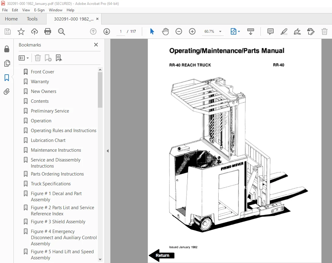
Front Cover 1
Warranty 2
New Owners 3
Contents 3
Preliminary Service 3
Operation 3
Operating Rules and Instructions 4
Lubrication Chart 10
Maintenance Instructions 12
Service and Disassembly Instructions 16
Parts Ordering Instructions 21
Truck Specifications 23
Figure # 1 Decal and Part Assembly 24
Figure # 2 Parts List and Service Reference Index 26
Figure # 3 Shield Assembly 28
Figure # 4 Emergency Disconnect and Auxiliary Control Assembly 30
Figure # 5 Hand Lift and Speed Assembly 32
Figure # 6 Master Control Switch Assembly 34
Figure # 7 Steering Control and Pump Assembly 36
Figure # 8 Auxiliary Pump Assembly 38
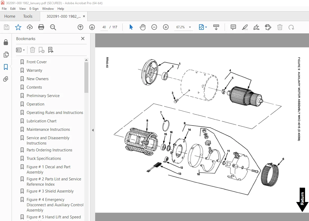
Figure # 9 Auxiliary Motor Assembly 40
Figure # 10 Transmission and Steering Insulation Assembly 42
Figure # 11 Brake Assembly 44
Figure # 12 Drive Motor Assembly 46
Figure # 13 Transmission Assembly 48
Figure # 14 Idler Wheel Insulation Assembly 50
Figure # 15 Electrical Schematic 52
Figure # 16 Electrical Schematic Symbols 53
Figure # 17 Wiring Harness Assembly 54
Figure # 18 Mast Cable Assembly 56
Figure # 19 Reach Cable Assembly 57
Figure # 20 Power Component Wiring 58
Figure # 21 SCR and Contactor Panel Assembly 60
Figure # 22 EV-1 SCR Control 62
Figure # 23 Transformer Assembly 63
Figure # 24 Rectifier Heat Sink Assembly 64
Figure # 25 GE Contactor Assembly 65
Figure # 26 Power Steering Contactor Assembly 66
Figure # 27 GE Contactor Assembly 67
Figure # 28 Hydraulic Schematic 68
Figure # 29 Hydraulic Schematic Symbols 69
Figure # 30 Hydraulic Assembly Part # 1 70
Figure # 31 Brake Solenoid Valve 71
Figure # 32 Brake Cylinder Assembly 72
Figure # 33 Hydraulic Reservoir Assembly 73
Figure # 34 Hydraulic Assembly Part # 2 74
Figure # 35 Lift Pump and Motor Assembly 75
Figure # 36 Lift Motor Assembly 76
Figure # 37 Lift Pump Assembly 77
Figure # 38 Lift Control Valve Assembly 78
Figure # 39 Hydraulic Assembly Part # 3 79
Figure # 40 Steer Control Valve 80
Figure # 41 Steer Cylinder Assembly 81
Figure # 42 Auxiliary Control Valve Assembly 82
Figure # 43 Hydraulic Assembly Part # 4 84
Figure # 44 Freelift Cylinder Assembly 86
Figure # 45 Staging Cylinder Assembly 87
Figure # 46 Mast Hydraulic Hose Assembly 88
Figure # 47 Standard Reach Hose Assembly 90
Figure # 48 Reach and Tilt Cylinder Assembly 92
Figure # 49 Reach with Tilt Hose Assembly 94
Figure # 50 Reach with Tilt Manifold Valve Assembly 96
Figure # 51 Sideshifter Hose Assembly 97
Figure # 52 Sideshifter Cylinder Assembly 98
Figure # 53 Sideshifter Manifold Valve 99
Figure # 54 3 Stage Mast Insulation Assembly 100
Figure # 55 Outer Column Assembly 102
Figure # 56 Intermediate Column Assembly 103
Figure # 57 Inner Column Assembly 104
Figure # 58 3 Stage Freelift Cylinder Assembly 106
Figure # 59 Reach Assembly 108
Figure # 60 Standard Reach Front Frame Assembly 110
Figure # 61 Tilt Reach Front Frame Assembly 111
Figure # 62 Fork Assembly 112
Figure # 63 Sideshifter Assembly 113
Figure # 64 Main Frame and Load Wheel Assembly 114
Service Guide 116
S.V 11/01/2025