BT Prime-Mover RR-34 Reach Truck Parts Manual – PDF DOWNLOAD
$26.95
BT Prime-Mover RR-34 Reach Truck Parts Manual – PDF DOWNLOAD
Description
BT Prime-Mover RR-34 Reach Truck Parts Manual – PDF DOWNLOAD
FILE DETAILS:
BT Prime-Mover RR-34 Reach Truck Parts Manual – PDF DOWNLOAD
Language : English
Pages : 100
Downloadable : Yes
File Type : PDF
IMAGES PREVIEW OF THE MANUAL:
TABLE OF CONTENTS:
BT Prime-Mover RR-34 Reach Truck Parts Manual – PDF DOWNLOAD
Front Cover 1
Warranty 2
Parts Ordering Instructions 3
General Information 4
Figure # 1 Parts List and Service Reference Index 6
Figure # 2 Decal and Part Assembly 8
Figure # 3 Shielding Assembly 9
Figure # 4 Emergency Disconnect Assembly 10
Figure # 5 Auxiliary Control Assembly 11
Figure # 6 Hand Lift and Speed Assembly 12
Figure # 7 Master Control Switch Assembly 14
Figure # 8 Steering Assembly 16
Figure # 9 Torque Generator Assembly 18
Figure # 10 Auxiliary Pump and Motor Assembly 19
Figure # 11 Auxiliary Pump Assembly 20
Figure # 12 Auxiliary Motor Assembly 21
Figure # 13 Transmission and Drive Motor Insulation 22
Figure # 14 Drive Motor and Brake Assembly 24
Figure # 15 Drive Motor Assembly 26
Figure # 16 Transmission Assembly 28
Figure # 17 Electrical Schematic 30
Figure # 18 Electrical Schematic Symbols 31
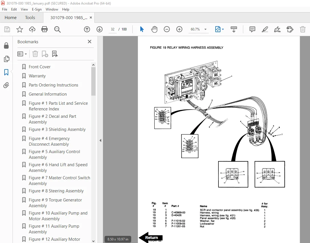
Figure # 19 Relay Wiring Harness Assembly 32
Figure # 20 Switch Relay Assembly 33
Figure # 21 Wiring Harness Assembly 34
Figure # 22 Wiring Assembly for Cold Storage 36
Figure # 23 Mast Cable Assembly 37
Figure # 24 Reach Cable Assembly 38
Figure # 25 Power Component Wiring 39
Figure # 26 SCR and Contactor Panel Assembly 40
Figure # 27 EV-1 SCR Control 41
Figure # 28 Transformer Assembly 42
Figure # 29 Rectifier Heat Sink Assembly 43
Figure # 30 G E Contactor Assembly 44
Figure # 31 G E Contactor Assembly 45
Figure # 32 Contactor Assembly 46
Figure # 33 Connector Assembly 47
Figure # 34 Warning Light Assembly 48
Figure # 35 Hydraulic Schematic 49
Figure # 36 Hydraulic Schematic Symbols 50
Figure # 37 Auxiliary Pump and Reservoir Assembly 51
Figure # 38 Hydraulic Reservoir Assembly 52
Figure # 39 Lift Pump and Motor Assembly 53
Figure # 40 Lift Pump and Motor Assembly 54
Figure # 41 Lift Motor Assembly 55
Figure # 42 24 Volt Lift Pump Assembly 56
Figure # 43 36 Volt Lift Pump Assembly 57
Figure # 44 Lift Control Valve Assembly 58
Figure # 45 Torque Generator and Filter Assembly 59
Figure # 46 Tube and Hose Assembly 60
Figure # 47 Auxiliary Control Valve Assembly 61
Figure # 48 3 Stage Cylinders and Reservoir Assembly 62
Figure # 49 Freelift Cylinder Assembly 64
Figure # 50 Staging Cylinder Assembly 65
Figure # 51 Mast Hydraulic Hose Assembly 66
Figure # 52 Standard Reach Hose Assembly 67
Figure # 53 Flow Divider Assembly 68
Figure # 54 Reach and Tilt Cylinder Assembly 69
Figure # 55 Reach with Tilt Hose Assembly 70
Figure # 56 Reach with Tilt Manifold Valve Assembly 71
Figure # 57 Sideshifter Hose Assembly 72
Figure # 58 Sideshifter Cylinder Assembly 73
Figure # 59 Sideshifter Manifold Valve Assembly 74
Figure # 60 Deep Reach Valve and Hose Assembly 75
Figure # 61 Deep Reach Cylinder and Hose Assembly 76
Figure # 62 Deep Reach Manifold Valve Assembly 77
Figure # 63 Deep Reach, Reach Cylinder Assembly 78
Figure # 64 Deep Reach, Tilt Cylinder and Hose Assembly 79
Figure # 65 Deep Reach, Tilt Cylinder Assembly 80
Figure # 66 Deep Reach Sideshifter Hose Assembly 81
Figure # 67 Mast Installation Assembly 82
Figure # 68 Stage Outer Column Assembly 83
Figure # 69 Intermediate Column Assembly 84
Figure # 70 3 Stage Inner Column Assembly 85
Figure # 71 Freelift Cylinder Assembly and Related Parts 86
Figure # 72 Single Reach Assembly 87
Figure # 73 Single Reach Standard Front Frame Assembly 88
Figure # 74 Single Reach Tilt Front Frame Assembly 89
Figure # 75 Deep Reach Assembly 90
Figure # 76 Sideshifter Assembly 91
Figure # 77 Fork Assembly 92
Figure # 78 Main Frame and Load Wheel Assembly 94
Figure # 79 Caster Assembly 96
Figure # 80 Single Load Wheel Assembly 98
Figure # 81 4 Inch High Outriggers Articulating Load Wheel Assembly 99
Figure # 82 Articulating Load Wheel Assembly 100
DESCRIPTION:
BT Prime-Mover RR-34 Reach Truck Parts Manual – PDF DOWNLOAD
PARTS ORDERING INSTRUCTIONS:
HOW TO ORDER:
- When you order, supply the part number, quantity and model and serial numbers of your machine. Supplying this information will assure prompt, efficient handling of your order. The pictorial reference number is not needed and including it can only add confusion.
- Since your dealer carries many parts in stock and maintains up-to-date prices on all parts, he will be able to process your order immediately. If, for some reason, the part is not in stock, he will order it from the factory. In either event, he maintains a current file of Service Bulletins, which give all available parts ordering or technical information.
- All prices are FOB factory in Muscatine, Iowa. Shipping charges are added to the price of the part shipped from the factory.
WHERE TO ORDER
Always order parts from the dealer who sold you your Prime-Mover. If it is necessary for the dealer to order parts from the factory, he is able to get prompt service for you. Parts are shipped in accordance with shipping instructions given on the order.
INSTRUCTIONS FOR RETURNING PARTS:
- Under no circumstances will parts be accepted at the factory for credit without prior approval. The Prime-Mover Co. cannot accept responsibility for parts returned without authorization.
- If you have some parts which must be returned, contact your dealer. If he believes parts should be returned, he will arrange for authorization to return the parts.
S.V 04/02/2025